HYUNDAI ENTOURAGE 2007 Owners Manual
Manufacturer: HYUNDAI, Model Year: 2007, Model line: ENTOURAGE, Model: HYUNDAI ENTOURAGE 2007Pages: 398, PDF Size: 8.03 MB
Page 361 of 398
647
Maintenance
Traction - AA, A, B & C
The traction grades, from highest to
lowest, are AA, A, B and C. The
grades represent the tires ability to
stop on wet pavement as measured
under controlled conditions on spec-
ified government test surfaces of
asphalt and concrete. A tire marked
C may have poor traction perform-
ance.
Temperature -A, B & C
The temperature grades are A (the
highest), B and C. The grades repre-
sent the tire’s resistance to the gen-
eration of heat and its ability to dissi-
pate heat when tested under con-
trolled conditions on a specified
indoor laboratory test wheel.
Sustained high temperature can
cause the material of the tire to degen-
erate and reduce tire life, and exces-
sive temperature can lead to sudden
tire failure. Grade C corresponds to a
level of performance which all passen-
ger vehicle tires must meet under the
Federal Motor Vehicle Safety
Standard No. 109. Grades A and B
represent higher levels of perform-
ance on the laboratory test wheel than
the minimum required by the law.
Tire terminology and defini-
tionsAir Pressure: The amount of air
inside the tire pressing outward on
the tire. Air pressure is expressed in
pounds per square inch (psi) or kilo-
pascal (kPa).
Accessory Weight: This means the
combined weight of optional acces-
sories. Some examples of optional
accessories are, automatic transmis-
sion, power seats, and air condition-
ing.
Aspect Ratio: The relationship of a
tire's height to its width.
Belt:A rubber coated layer of cords
that is located between the plies and
the tread. Cords may be made from
steel or other reinforcing materials.
Bead: The tire bead contains steel
wires wrapped by steel cords that
hold the tire onto the rim.
Bias Ply Tire: A pneumatic tire in
which the plies are laid at alternate
angles less than 90 degrees to the
centerline of the tread.
WARNING
- Tire
temperature
The temperature grade for this
tire is established for a tire that
is properly inflated and not
overloaded. Excessive speed,
underinflation, or excessive
loading, either separately or in
combination, can cause heat
build-up and possible sudden
tire failure. This can cause loss
of vehicle control and serious
injury or death.
Page 362 of 398
Maintenance48 6Cold Tire Pressure: The amount of
air pressure in a tire, measured in
pounds per square inch (psi) or kilo-
pascals (kPa) before a tire has built
up heat from driving.
Curb Weight: This means the weight
of a motor vehicle with standard and
optional equipment including the
maximum capacity of fuel, oil and
coolant, but without passengers and
cargo.
DOT Markings: A code molded into
the sidewall of a tire signifying that
the tire is in compliance with the U.S.
Department of Transportation motor
vehicle safety standards. The DOT
code includes the Tire Identification
Number (TIN), an alphanumeric des-
ignator which can also identify the
tire manufacturer, production plant,
brand and date of production.
GVWR: Gross Vehicle Weight Rating
GAWR FRT: Gross Axle Weight
Rating for the front Axle.
GAWR RR: Gross Axle Weight
Rating for the rear axle.Intended Outboard Sidewall: The
side of an asymmetrical tire, that
must always face outward when
mounted on a vehicle.
Kilopascal (kPa): The metric unit for
air pressure.
Load Index: An assigned number
ranging from 1 to 279 that corre-
sponds to the load carrying capacity
of a tire.
Maximum Inflation Pressure: The
maximum air pressure to which a
cold tire may be inflated. The maxi-
mum air pressure is molded onto the
sidewall.
Maximum Load Rating: The load
rating for a tire at the maximum per-
missible inflation pressure for that
tire.
Maximum Loaded Vehicle Weight:
The sum of curb weight; accessory
weight; vehicle capacity weight; and
production options weight.
Normal Occupant Weight:The
number of occupants a vehicle is
designed to seat multiplied by 150
pounds (68 kg).Occupant Distribution: Designated
seating positions.
Outward Facing Sidewall:The side
of a asymmetrical tire that has a par-
ticular side that faces outward when
mounted on a vehicle. The outward
facing sidewall bears white lettering
or bears manufacturer, brand, and/or
model name molding that is higher or
deeper than the same moldings on
the inner facing sidewall.
Passenger (P-Metric) Tire: A tire
used on passenger cars and some
light duty trucks and multipurpose
vehicles.
Recommended Inflation Pressure:
Vehicle manufacturer's recommend-
ed tire inflation pressure and shown
on the tire placard.
Radial Ply Tire: A pneumatic tire in
which the ply cords that extend to the
beads are laid at 90 degrees to the
centerline of the tread.
Rim: A metal support for a tire and
upon which the tire beads are seat-
ed.
Sidewall: The portion of a tire
between the tread and the bead.
Page 363 of 398
649
Maintenance
Speed Rating: An alphanumeric
code assigned to a tire indicating the
maximum speed at which a tire can
operate.
Traction: The friction between the
tire and the road surface. The
amount of grip provided.
Tr e a d: The portion of a tire that
comes into contact with the road.
Treadwear Indicators: Narrow
bands, sometimes called "wear
bars," that show across the tread of a
tire when only 2/32 inch of tread
remains.
UTQGS: Uniform Tire Quality
Grading Standards, a tire information
system that provides consumers with
ratings for a tire's traction, tempera-
ture and treadwear. Ratings are
determined by tire manufacturers
using government testing proce-
dures. The ratings are molded into
the sidewall of the tire.
Vehicle Capacity Weight: The num-
ber of designated seating positions
multiplied by 150 lbs. (68 kg) plus the
rated cargo and luggage load.Vehicle Maximum Load on the
Tire: Load on an individual tire due to
curb and accessory weight plus
maximum occupant and cargo
weight.
Vehicle Normal Load on the Tire:
Load on an individual tire that is
determined by distributing to each
axle its share of the curb weight,
accessory weight, and normal occu-
pant weight and driving by 2.
Vehicle Placard: A label permanent-
ly attached to a vehicle showing the
original equipment tire size and rec-
ommended inflation pressure.
All season tires Hyundai specifies all season tires on
some models to provide good per-
formance for use all year round,
including snowy and icy road condi-
tions. All season tires are identified
by ALL SEASON and/or M+S (Mud
and Snow) on the tire sidewall. Snow
tires have better snow traction than
all season tires and may be more
appropriate in some areas.Summer tires Hyundai specifies summer tires on
some models to provide superior
performance on dry roads. Summer
tire performance is substantially
reduced in snow and ice. Summer
tires do not have the tire traction rat-
ing M+S (Mud and Snow) on the tire
side wall. if you plan to operate your
vehicle in snowy or icy conditions.
Hyundai recommends the use of
snow tires or all season tires on all
four wheels.
Page 364 of 398
Maintenance50 6Snow tiresIf you equip your car with snow tires,
they should be the same size and
have the same load capacity as the
original tires. Snow tires should be
installed on all four wheels; other-
wise, poor handling may result.
Snow tires should carry 4 psi (28
kPa) more air pressure than the
pressure recommended for the stan-
dard tires on the tire label on the dri-
ver's side of the center pillar, or up to
the maximum pressure shown on the
tire sidewall, whichever is less.
Do not drive faster than 75 mph (120
km/h) when your car is equipped with
snow tires.Tire chainsTire chains, if necessary, should be
installed on the drive wheels (front
wheel).
Be sure that the chains are installed
in accordance with the manufactur-
er's instructions.
To minimize tire and chain wear, do
not continue to use tire chains when
they are no longer needed.
WARNING
- Snow or ice
When driving on roads cov-
ered with snow or ice, drive at
less than 20 mph (30 km/h).
Use the SAE “S” class or wire
chains.
If you have noise caused by
chains contacting the body,
retighten the chain to avoid
contact with the vehicle body.
To prevent body damage,
retighten the chains after driv-
ing 0.3~0.6 miles.
Do not use tire chains on vehi-
cles equipped with aluminum
wheels. In unavoidable cir-
cumstance, use a wire type
chain.
Use wire chains less than
15mm to prevent damage to
the chain’s connection.
CAUTION
If you hear noise caused by
chains contacting the body,
retighten the chain to avoid
contact with the vehicle body.
To prevent body damage,
retighten the chains after driv-
ing 0.3 ~ 0.6 miles (0.5 ~ 1.0 km).
Page 365 of 398
651
Maintenance
LIGHT BULBS REPLACEMENT Use only the bulbs of the specified
wattage.
✽ ✽
NOTICEAfter driving in heavy rain or washing,
headlight and taillight lenses could
appear frosty. This condition is caused by
the temperature difference between the
lamp inside and outside. This is similar
to the condensation on your windows
inside your vehicle during the rain and
doesn’t indicate a problem with your
vehicle. If the water leaks into the lamp
bulb circuitry, have the vehicle checked
by an Authorized Hyundai Dealer.
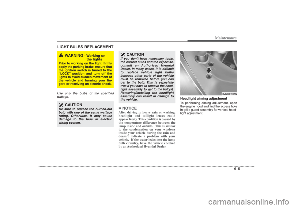
Headlight aiming adjustmentTo performing aiming adjustment, open
the engine hood and find the access hole
in grille guard assembly for vertical head-
light adjustment.
WARNING
- Working on
the lights
Prior to working on the light, firmly
apply the parking brake, ensure that
the ignition switch is turned to the
“LOCK” position and turn off the
lights to avoid sudden movement of
the vehicle and burning your fin-
gers or receiving an electric shock.
CAUTION
Be sure to replace the burned-out
bulb with one of the same wattage
rating. Otherwise, it may cause
damage to the fuse or electric
wiring system.
CAUTION
If you don’t have necessary tools,
the correct bulbs and the expertise,
consult an Authorized Hyundai
Dealer. In many cases, it is difficult
to replace vehicle light bulbs
because other parts of the vehicle
must be removed before you can
get to the bulb. This is especially
true if you have to remove the head-
light assembly to
get to the bulb(s).
Removing/installing
the headlight
assembly can result in damage to
the vehicle.
OVQ036901N
Page 366 of 398
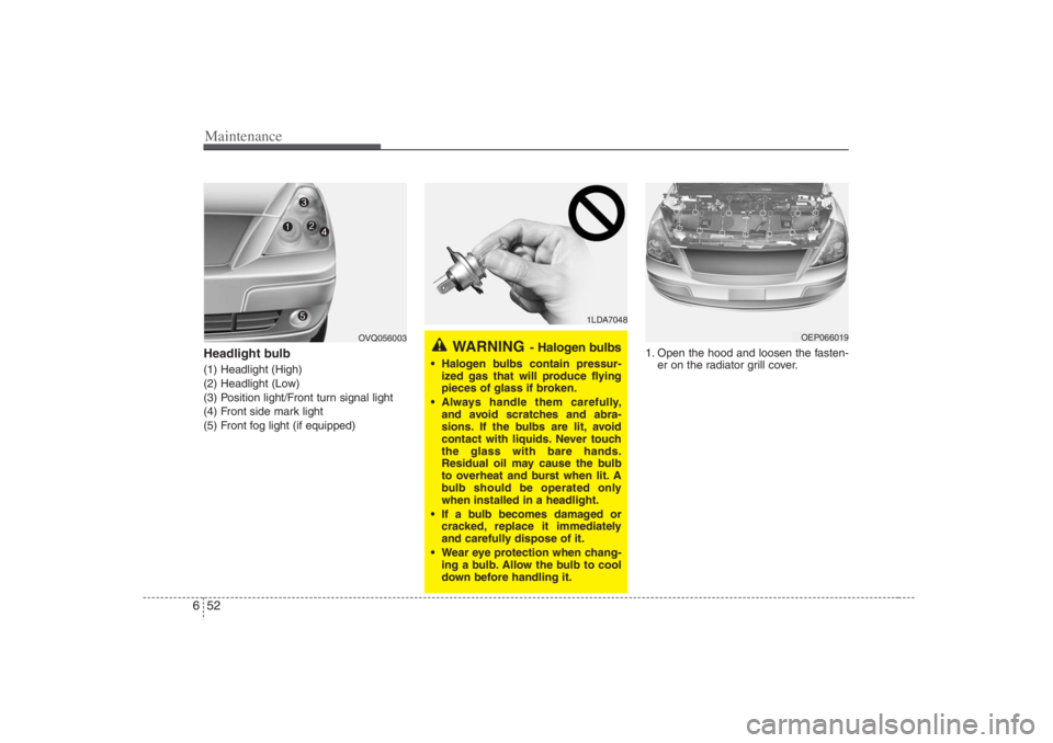
Maintenance52 6Headlight bulb (1) Headlight (High)
(2) Headlight (Low)
(3) Position light/Front turn signal light
(4) Front side mark light
(5) Front fog light (if equipped)1. Open the hood and loosen the fasten-
er on the radiator grill cover.
1LDA7048
WARNING
- Halogen bulbs
Halogen bulbs contain pressur-
ized gas that will produce flying
pieces of glass if broken.
Always handle them carefully,
and avoid scratches and abra-
sions. If the bulbs are lit, avoid
contact with liquids. Never touch
the glass with bare hands.
Residual oil may cause the bulb
to overheat and burst when lit. A
bulb should be operated only
when installed in a headlight.
If a bulb becomes damaged or
cracked, replace it immediately
and carefully dispose of it.
Wear eye protection when chang-
ing a bulb. Allow the bulb to cool
down before handling it.
OEP066019
OVQ056003
Page 367 of 398
653
Maintenance
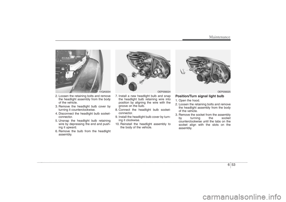
2. Loosen the retaining bolts and remove
the headlight assembly from the body
of the vehicle.
3. Remove the headlight bulb cover by
turning it counterclockwise.
4. Disconnect the headlight bulb socket-
connector.
5. Unsnap the headlight bulb retaining
wire by depressing the end and push-
ing it upward.
6. Remove the bulb from the headlight
assembly.7. Install a new headlight bulb and snap
the headlight bulb retaining wire into
position by aligning the wire with the
groove on the bulb.
8. Connect the headlight bulb socket-
connector.
9. Install the headlight bulb cover by turn-
ing it clockwise.
10. Reinstall the headlight assembly to
the body of the vehicle.
Position/Turn signal light bulb1. Open the hood.
2. Loosen the retaining bolts and remove
the headlight assembly from the body
of the vehicle.
3. Remove the socket from the assembly
by turning the socket
counterclockwise until the tabs on the
socket align with the slots on the
assembly.
1VQA5034
OEP056024
OEP056025
Page 368 of 398
Maintenance54 64. Remove the bulb from the socket by
pressing it in and rotating it until the
tabs on the bulb align with the slots in
the socket. Pull the bulb out of the
socket.
5. Insert a new bulb by inserting it into
the socket and rotating it until it locks
into place.
6. Install the socket in the assembly by
aligning the tabs on the socket with the
slots in the assembly. Insert the socket
into the assembly and turn the socket
clockwise.
7. Reinstall the headlight assembly to the
body of the vehicle.
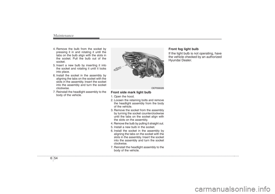
Front side mark light bulb1. Open the hood.
2. Loosen the retaining bolts and remove
the headlight assembly from the body
of the vehicle.
3. Remove the socket from the assembly
by turning the socket counterclockwise
until the tabs on the socket align with
the slots on the assembly.
4. Remove the bulb by pulling it straight out.
5. Install a new bulb in the socket.
6. Install the socket in the assembly by
aligning the tabs on the socket with the
slots in the assembly. Insert the socket
into the assembly and turn the socket
clockwise.
7. Reinstall the headlight assembly to the
body of the vehicle.
Front fog light bulb
If the light bulb is not operating, have
the vehicle checked by an authorized
Hyundai Dealer.
OEP056026
Page 369 of 398
655
Maintenance
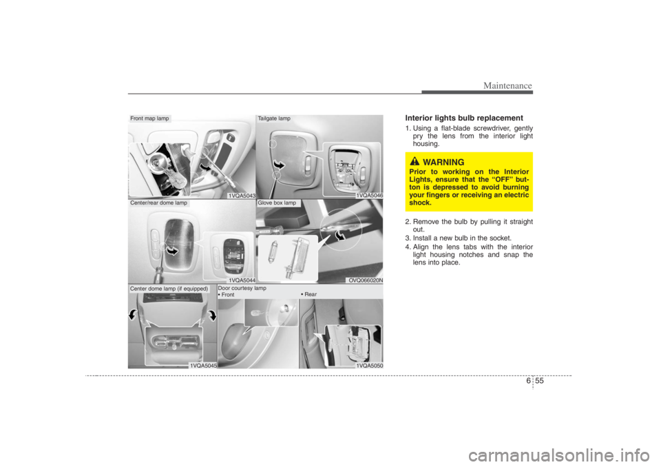
Interior lights bulb replacement1. Using a flat-blade screwdriver, gently
pry the lens from the interior light
housing.
2. Remove the bulb by pulling it straight
out.
3. Install a new bulb in the socket.
4. Align the lens tabs with the interior
light housing notches and snap the
lens into place.
1VQA5046OVQ066020N
Tailgate lampGlove box lamp
1VQA50431VQA5044
Front map lampCenter/rear dome lampCenter dome lamp (if equipped)
1VQA5050
1VQA5045
Door courtesy lamp
Front
Rear
WARNING
Prior to working on the Interior
Lights, ensure that the “OFF” but-
ton is depressed to avoid burning
your fingers or receiving an electric
shock.
Page 370 of 398
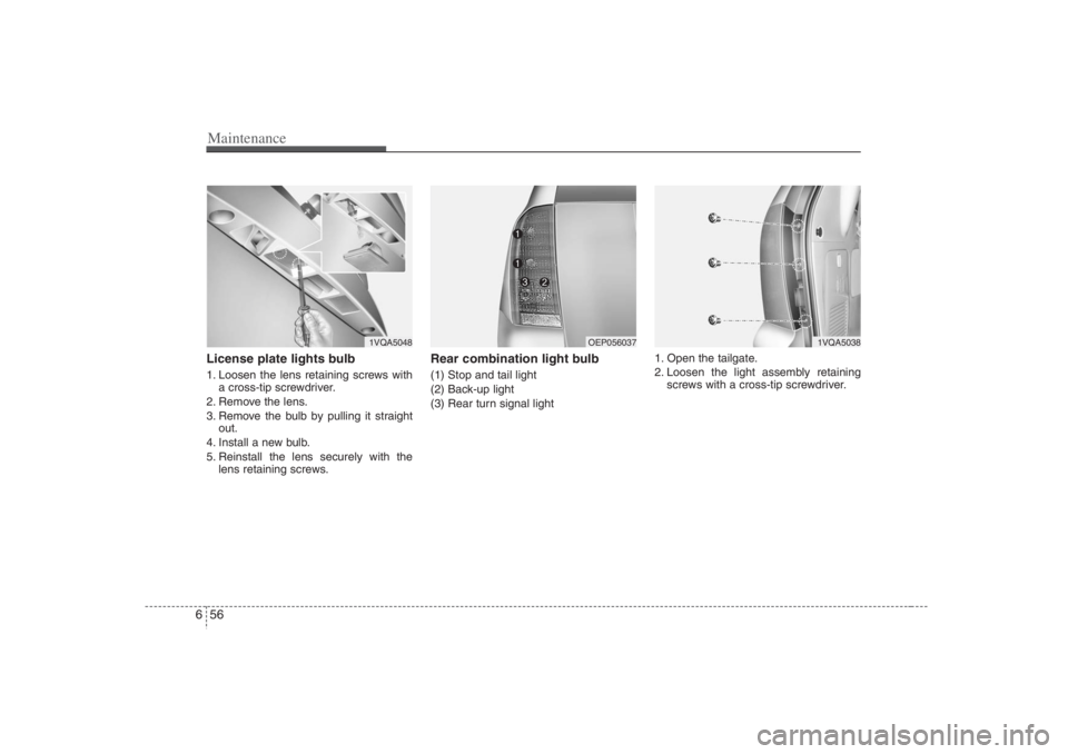
Maintenance56 6License plate lights bulb 1. Loosen the lens retaining screws with
a cross-tip screwdriver.
2. Remove the lens.
3. Remove the bulb by pulling it straight
out.
4. Install a new bulb.
5. Reinstall the lens securely with the
lens retaining screws.
Rear combination light bulb (1) Stop and tail light
(2) Back-up light
(3) Rear turn signal light1. Open the tailgate.
2. Loosen the light assembly retaining
screws with a cross-tip screwdriver.
1VQA5048
OEP056037
1VQA5038