esc HYUNDAI ENTOURAGE 2008 Owner's Manual
[x] Cancel search | Manufacturer: HYUNDAI, Model Year: 2008, Model line: ENTOURAGE, Model: HYUNDAI ENTOURAGE 2008Pages: 393, PDF Size: 8.78 MB
Page 283 of 393
443
Driving your vehilcle
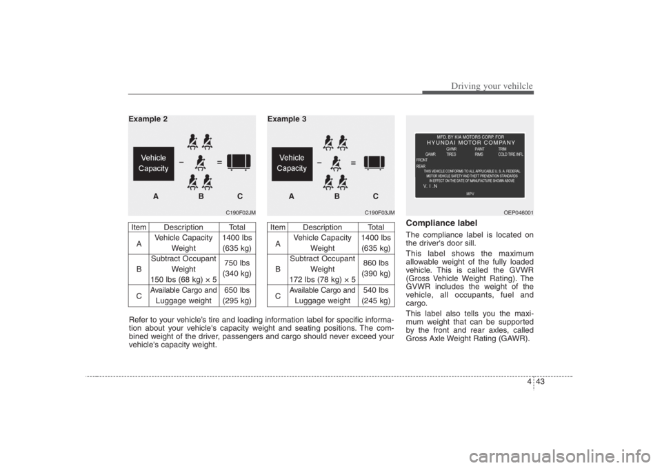
Compliance labelThe compliance label is located on
the driver's door sill.
This label shows the maximum
allowable weight of the fully loaded
vehicle. This is called the GVWR
(Gross Vehicle Weight Rating). The
GVWR includes the weight of the
vehicle, all occupants, fuel and
cargo.
This label also tells you the maxi-
mum weight that can be supported
by the front and rear axles, called
Gross Axle Weight Rating (GAWR).
C190F02JM
Item Description Total
AVehicle Capacity 1400 lbs
Weight (635 kg)
Subtract Occupant
B Weight 750 lbs
150 lbs (68 kg) × 5(340 kg)
C
Available Cargo and
650 lbs
Luggage weight (295 kg)
ABC Example 2
C190F03JM
Item Description Total
AVehicle Capacity 1400 lbs
Weight (635 kg)
Subtract Occupant
B Weight 860 lbs
172 lbs (78 kg) × 5(390 kg)
C
Available Cargo and
540 lbs
Luggage weight (245 kg)
ABC Example 3
Refer to your vehicle’s tire and loading information label for specific informa-
tion about your vehicle's capacity weight and seating positions. The com-
bined weight of the driver, passengers and cargo should never exceed your
vehicle's capacity weight.
OEP046001
Page 312 of 393
63
Maintenance
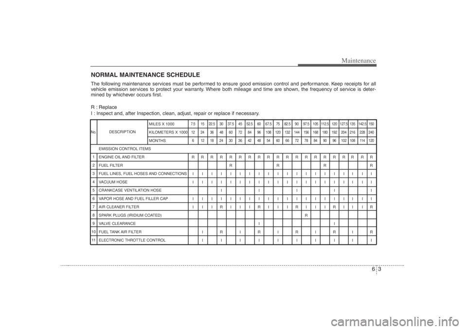
NORMAL MAINTENANCE SCHEDULE
DESCRIPTION
The following maintenance services must be performed to ensure good emission control and performance. Keep receipts for all
vehicle emission services to protect your warranty. Where both mileage and time are shown, the frequency of service is deter-
mined by whichever occurs first.
R : Replace
I : Inspect and, after Inspection, clean, adjust, repair or replace if necessary.
7.5 15 22.5 30 37.5 45 52.5 60 67.5 75 82.5 90 97.5 105 112.5 120 127.5 135 142.5 150
12 24 36 48 60 72 84 96 108 120 132 144 156 168 180 192 204 216 228 240
6 121824303642485460667278849096102108114120RRRRRRRRRRRRRRRRRR RR
RRRR
IIIIIIIIIIIIIIIIII II
IIIIIIIIIIIIIIIIII II
IIIII
IIIIIIIIIIIIIIIIII II
I I IRI I IRI I IRI I IRII IR
R
II
IRIRIRIRIR
IIIIIIIIII EMISSION CONTROL ITEMS
ENGINE OIL AND FILTER
FUEL FILTER
FUEL LINES, FUEL HOSES AND CONNECTIONS
VACUUM HOSE
CRANKCASE VENTILATION HOSE
VAPOR HOSE AND FUEL FILLER CAP
AIR CLEANER FILTER
SPARK PLUGS (IRIDIUM COATED)
VALVE CLEARANCE
FUEL TANK AIR FILTER
ELECTRONIC THROTTLE CONTROL
No.1
2
3
4
5
6
7
8
9
10
11MILES X 1000
KILOMETERS X 1000
MONTHS
Page 313 of 393
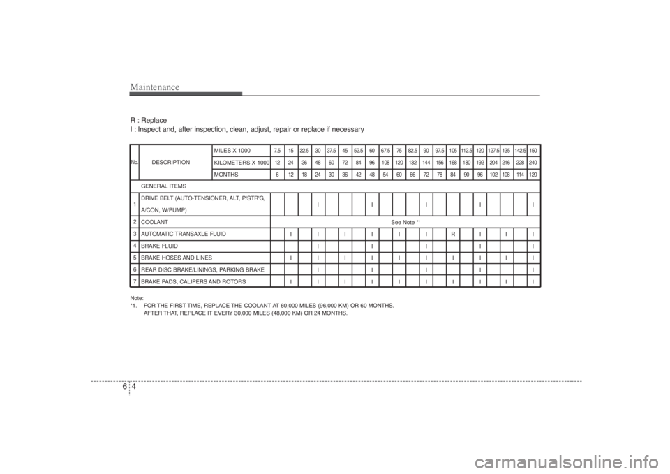
Maintenance4 6Note:
*1. FOR THE FIRST TIME, REPLACE THE COOLANT AT 60,000 MILES (96,000 KM) OR 60 MONTHS.
AFTER THAT, REPLACE IT EVERY 30,000 MILES (48,000 KM) OR 24 MONTHS.DESCRIPTION
7.5 15 22.5 30 37.5 45 52.5 60 67.5 75 82.5 90 97.5 105 112.5 120 127.5 135 142.5 150
12 24 36 48 60 72 84 96 108 120 132 144 156 168 180 192 204 216 228 240
6 121824303642485460667278849096102108114120
IIIII
See Note *
1
IIIIIIRIII
IIIII
IIIIIIIIII
IIIII
IIIIIIIIII GENERAL ITEMS
DRIVE BELT (AUTO-TENSIONER, ALT, P/STR'G,
A/CON, W/PUMP)
COOLANT
AUTOMATIC TRANSAXLE FLUID
BRAKE FLUID
BRAKE HOSES AND LINES
REAR DISC BRAKE/LININGS, PARKING BRAKE
BRAKE PADS, CALIPERS AND ROTORSMILES X 1000
KILOMETERS X 1000
MONTHS
R : Replace
I : Inspect and, after inspection, clean, adjust, repair or replace if necessaryNo.1
2
3
4
5
6
7
Page 314 of 393
65
Maintenance
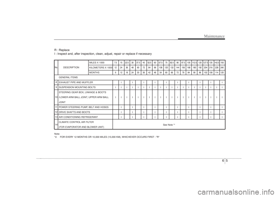
R : Replace
I : Inspect and, after inspection, clean, adjust, repair or replace if necessaryNote:
*2. FOR EVERY 12 MONTHS OR 10,000 MILES (15,000 KM), WHICHEVER OCCURS FIRST : "R"DESCRIPTION
7.5 15 22.5 30 37.5 45 52.5 60 67.5 75 82.5 90 97.5 105 112.5 120 127.5 135 142.5 150
12 24 36 48 60 72 84 96 108 120 132 144 156 168 180 192 204 216 228 240
6 121824303642485460667278849096102108114120
IIIIIIIIII
IIIIIIIIIIIIIIIIII II
IIIIIIIIIIIIIIIIII II
IIIIIIIIII
IIIIIIIIII
IIIIIIIIII
See Note *
2
GENERAL ITEMS
EXHAUST PIPE AND MUFFLER
SUSPENSION MOUNTING BOLTS
STEERING GEAR BOX, LINKAGE & BOOTS
/LOWER ARM BALL JOINT, UPPER ARM BALL
JOINT
POWER STEERING PUMP, BELT AND HOSES
DRIVE SHAFTS AND BOOTS
AIR CONDITIONING REFRIGERANT
CLIMATE CONTROL AIR FILTER
(FOR EVAPORATOR AND BLOWER UNIT)MILES X 1000
KILOMETERS X 1000
MONTHS
No.8
9
10
11
12
13
14
Page 317 of 393
Maintenance8 6Automatic transaxle fluid The fluid level should be in the “HOT”
range of the dipstick, after the engine
and transaxle are at normal operating
temperature. Check the automatic
transaxle fluid level with the engine run-
ning and the transaxle in neutral, with the
parking brake properly applied. Use
HYUNDAI GENUINE ATF SP-III, DIA-
MOND ATF SP-III, SK ATF SP-III or other
brands meeting the SP III specification
approved by Hyundai Motor Co. when
adding or changing fluid. Using the
wrong ATF may result in damage to the
ATM.Brake hoses and linesVisually check for proper installation,
chafing, cracks, deterioration and any
leakage. Replace any deteriorated or
damaged parts immediately.Brake fluidCheck brake fluid level in the brake fluid
reservoir. The level should be between
"MIN" and "MAX" marks on the side of
the reservoir. Use only hydraulic brake
fluid conforming to DOT 3 or DOT 4.
Rear disc brake / linings, parking
brakeCheck the rear disc brake and linings for
scoring, burning, leaking fluid, broken
parts, and excessive wear. Inspect the
parking brake system including the park-
ing brake pedal and cables. For detailed
service procedures, refer to the Shop
Manual.Brake pads, calipers and rotorsCheck the pads for excessive wear, discs
for run out and wear, and calipers for fluid
leakage.Exhaust pipe and mufflerVisually inspect the exhaust pipes, muf-
fler and hangers for cracks, deterioration,
or damage. Start the engine and listen
carefully for any exhaust gas leakage.
Tighten connections or replace parts as
necessary.Suspension mounting boltsCheck the suspension connections for
looseness or damage. Retighten to the
specified torque.
Steering gear box, linkage &
boots/lower arm ball joint, upper
arm ball jointWith the vehicle stopped and engine off,
check for excessive free-play in the steer-
ing wheel. Check the linkage for bends or
damage. Check the dust boots and ball
joints for deterioration, cracks, or dam-
age. Replace any damaged parts.Power steering pump, belt and
hosesCheck the power steering pump and
hoses for leakage and damage. Replace
any damaged or leaking parts immediate-
ly. Inspect the power steering belt (or
drive belt) for evidence of cuts, cracks,
excessive wear, oiliness and proper ten-
sion. Replace or adjust it if necessary.Drive shafts and bootsCheck the drive shafts, boots and clamps
for cracks, deterioration, or damage.
Replace any damaged parts and, if nec-
essary, repack the grease.Air conditioning refrigerantCheck the air conditioning lines and con-
nections for leakage and damage. Check
air conditioning performance according to
the relevant shop manual if necessary.
Page 322 of 393
613
Maintenance
ENGINE COOLANTThe high-pressure cooling system has a
reservoir filled with year-round antifreeze
coolant. The reservoir is filled at the fac-
tory.
Check the antifreeze protection and
coolant level at least once a year, at the
beginning of the winter season, and
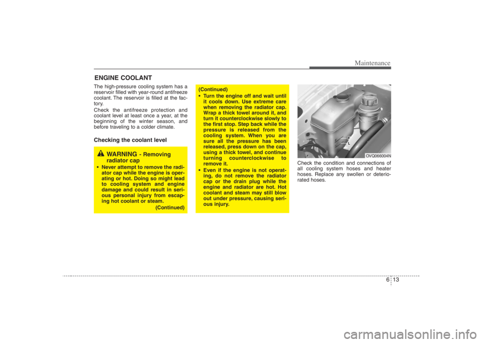
before traveling to a colder climate.Checking the coolant level
Check the condition and connections of
all cooling system hoses and heater
hoses. Replace any swollen or deterio-
rated hoses.
WARNING
- Removing
radiator cap
Never attempt to remove the radi-
ator cap while the engine is oper-
ating or hot. Doing so might lead
to cooling system and engine
damage and could result in seri-
ous personal injury from escap-
ing hot coolant or steam.
(Continued)
(Continued)
Turn the engine off and wait until
it cools down. Use extreme care
when removing the radiator cap.
Wrap a thick towel around it, and
turn it counterclockwise slowly to
the first stop. Step back while the
pressure is released from the
cooling system. When you are
sure all the pressure has been
released, press down on the cap,
using a thick towel, and continue
turning counterclockwise to
remove it.
Even if the engine is not operat-
ing, do not remove the radiator
cap or the drain plug while the
engine and radiator are hot. Hot
coolant and steam may still blow
out under pressure, causing seri-
ous injury.
OVQ066004N
Page 328 of 393
619
Maintenance
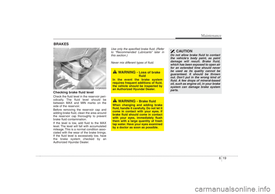
BRAKESChecking brake fluid level Check the fluid level in the reservoir peri-
odically. The fluid level should be
between MAX and MIN marks on the
side of the reservoir.
Before removing the reservoir cap and
adding brake fluid, clean the area around
the reservoir cap thoroughly to prevent
brake fluid contamination.
If the level is low, add fluid to the MAX
level. The level will fall with accumulated
mileage. This is a normal condition asso-
ciated with the wear of the brake linings.
If the fluid level is excessively low, have
the brake system checked by an
Authorized Hyundai Dealer.
Use only the specified brake fluid. (Refer
to “Recommended Lubricants” later in
this section.)
Never mix different types of fluid.
WARNING -
Brake fluid
When changing and adding brake
fluid, handle it carefully. Do not let it
come in contact with your eyes. If
brake fluid should come in contact
with your eyes, immediately flush
them with a large quantity of fresh
tap water. Have your eyes examined
by a doctor as soon as possible.
WARNING -
Loss of brake
fluid
In the event the brake system
requires frequent additions of fluid,
the vehicle should be inspected by
an Authorized Hyundai Dealer.
1VQA5020
CAUTION
Do not allow brake fluid to contact
the vehicle's body paint, as paint
damage will result. Brake fluid,
which has been exposed to open air
for an extended time should never
be used as its quality cannot be
guaranteed. It should be thrown
out. Don't put in the wrong kind of
fluid. A few drops of mineral-based
oil, such as engine oil, in your brake
system can damage brake system
parts.
Page 330 of 393
621
Maintenance
POWER STEERING Checking the power steering fluid
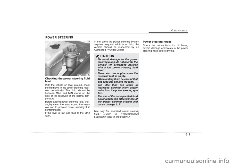
level With the vehicle on level ground, check
the fluid level in the power steering reser-
voir periodically. The fluid should be
between MAX and MIN marks on the
side of the reservoir at the normal tem-
perature.
Before adding power steering fluid, thor-
oughly clean the area around the reser-
voir cap to prevent power steering fluid
contamination.
If the level is low, add fluid to the MAX
level.In the event the power steering system
requires frequent addition of fluid, the
vehicle should be inspected by an
Authorized Hyundai Dealer.
Use only the specified power steering
fluid. (Refer to "Recommended
Lubricants" later in this section.)
Power steering hosesCheck the connections for oil leaks,
severe damage and twists in the power
steering hose before driving.
CAUTION
To avoid damage to the power
steering pump, do not operate the
vehicle for prolonged periods
with a low power steering fluid
level.
Never start the engine when the
reservoir tank is empty.
When adding fluid, be careful that
dirt does not get into the tank.
Too little fluid can result in
increased steering effort and/or
noise from the power steering sys-
tem.
The use of the non-specified fluid
could reduce the effectiveness of
the power steering system and
cause damage to it.
OVQ066012N
Page 338 of 393
629
Maintenance
✽ ✽
NOTICENot all fuse panel descriptions in this
manual may be applicable to your vehi-
cle. It is accurate at the time of printing.
When you inspect the fuse box on your
vehicle, refer to the fuse box label.
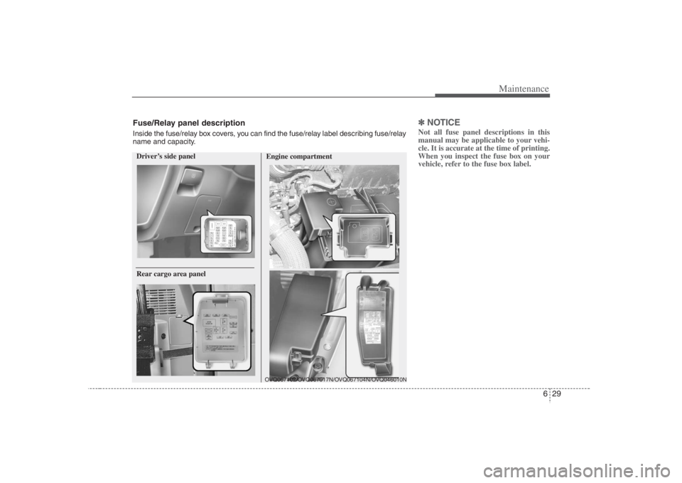
Driver’s side panel
Engine compartmentOVQ067102/OVQ067017N/OVQ067104N/OVQ046010N
Rear cargo area panelFuse/Relay panel descriptionInside the fuse/relay box covers, you can find the fuse/relay label describing fuse/relay
name and capacity.
Page 339 of 393
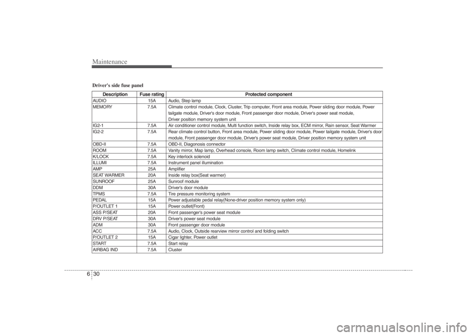
Maintenance30 6Driver's side fuse panel
Description Fuse rating Protected component
AUDIO 15A Audio, Step lamp
MEMORY 7.5A Climate control module, Clock, Cluster, Trip computer, Front area module, Power sliding door module, Power
tailgate module, Driver's door module, Front passenger door module, Driver's power seat module,
Driver position memory system unit
IG2-1 7.5A Air conditioner control module, Multi function switch, Inside relay box, ECM mirror, Rain sensor, Seat Warmer
IG2-2 7.5A Rear climate control button, Front area module, Power sliding door module, Power tailgate module, Driver's door
module, Front passenger door module, Driver's power seat module, Driver position memory system unit
OBD-II 7.5A OBD-II, Diagonosis connector
ROOM 7.5A Vanity mirror, Map lamp, Overhead console, Room lamp switch, Climate control module, Homelink
K/LOCK 7.5A Key interlock solenoid
ILLUMI 7.5A Instrument panel illumination
AMP 25A Amplifier
SEAT WARMER 20A Inside relay box(Seat warmer)
SUNROOF 25A Sunroof module
DDM 30A Driver's door module
TPMS 7.5A Tire pressure monitoring system
PEDAL 15A Power adjustable pedal relay(None-driver position memory system only)
P/OUTLET 1 15A Power outlet(Front)
ASS P/SEAT 20A Front passenger's power seat module
DRV P/SEAT 30A Driver's power seat module
ADM 30A Front passenger door module
ACC 7.5A Audio, Clock, Outside rearview mirror control and folding switch
P/OUTLET 2 15A Cigar lighter, Power outlet
START 7.5A Start relay
AIRBAG IND 7.5A Cluster