ABS Hyundai Genesis Coupe 2015 User Guide
[x] Cancel search | Manufacturer: HYUNDAI, Model Year: 2015, Model line: Genesis Coupe, Model: Hyundai Genesis Coupe 2015Pages: 438, PDF Size: 40.35 MB
Page 280 of 438
Driving your vehicle
30 5
✽
✽
NOTICE
A click sound may be heard in the
engine compartment when the vehi-
cle begins to move after the engine is
started. These conditions are normal
and indicate that the anti-lock brake
system is functioning properly.
Even with the anti-lock brake sys-
tem, your vehicle still requires suf-
ficient stopping distance. Always
maintain a safe distance from the
vehicle in front of you.
Always slow down when cornering.
The anti-lock brake system cannot
prevent accidents resulting from
excessive speeds.
On loose or uneven road surfaces,
operation of the anti-lock brake
system may result in a longer stop-
ping distance than for vehicles
equipped with a conventional
brake system.
✽ ✽
NOTICE
When you jump start your vehicle
because of a drained battery, the
engine may not run as smoothly and
the ABS warning light may turn on
at the same time. This happens
because of the low battery voltage. It
does not mean your ABS is malfunc-
tioning.
• Do not pump your brakes!
• Have the battery recharged before
driving the vehicle.
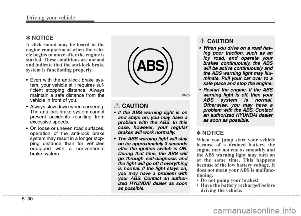
W-78
CAUTION
If the ABS warning light is on
and stays on, you may have a
problem with the ABS. In this
case, however, your regular
brakes will work normally.
The ABS warning light will stay
on for approximately 3 seconds
after the ignition switch is ON.
During that time, the ABS will
go through self-diagnosis and
the light will go off if everything
is normal. If the light stays on,
you may have a problem with
your ABS. Contact an author-
ized HYUNDAI dealer as soon
as possible.
CAUTION
When you drive on a road hav-
ing poor traction, such as an
icy road, and operate your
brakes continuously, the ABS
will be active continuously and
the ABS warning light may illu-
minate. Pull your car over to a
safe place and stop the engine.
Restart the engine. If the ABS
warning light is off, then your
ABS system is normal.
Otherwise, you may have a
problem with the ABS. Contact
an authorized HYUNDAI dealer
as soon as possible.
Page 284 of 438
Driving your vehicle
34 5
ESC OFF indicator
The ESC OFF indicator will illumi-
nate when the ignition switch is
turned ON, but should go off after
approximately 3 seconds. To switch
to ESC OFF mode, press the ESC
OFF button . The ESC OFF indica-
tor will illuminate indicating the
ESC is deactivated.
If this indicator stays on when ESC
OFF is not selected, the ESC may
have a malfunction. Take your car to
an authorized HYUNDAI dealer and
have the system checked.
With the ESC system in the stand by
position, if you use the parking brake
to stop the vehicle due to abnormal
brake operation, the ESC system
may be stopped and ESC OFF indi-
cator may illuminate for about 5
minutes.
ESC OFF usage
When driving
ESC should be turned on for daily
driving whenever possible. If ESC
is turned off, it may be difficult to
make a turn or drive up a hill.
To turn ESC off while driving, press
the ESC OFF button while driv-
ing on a flat road surface.
Never press the ESC OFF button
while ESC is operating (ESC indica-
tor light blinks).
If ESC is turned off while ESC is
operating, it may be very dangerous
because of unexpected vehicle slip.
✽ ✽
NOTICE
• When operating the vehicle on a
dynamometer, ensure that the
ESC is turned off (ESC OFF light
illuminated). If the ESC is left
on, it may prevent the vehicle
speed from increasing, and result
in false diagnosis.
• Turning the ESC off does not
affect ABS or brake system opera-
tion.
CAUTION
Driving with varying tire or
wheel sizes may cause the ESC
system to malfunction. When
replacing tires, make sure they
are the same size as your origi-
nal tires.
WARNING
The Electronic Stability Control
system is only a driving aid; use
precautions for safe driving by
slowing down on curved, snowy,
or icy roads. Drive slowly and
don’t attempt to accelerate
whenever the ESC indicator
light is blinking, or when the
road surface is slippery.
CAUTION
Do not use the parking brake to
stop the vehicle, except in an
emergency situation.
Page 293 of 438
543
Driving your vehicle
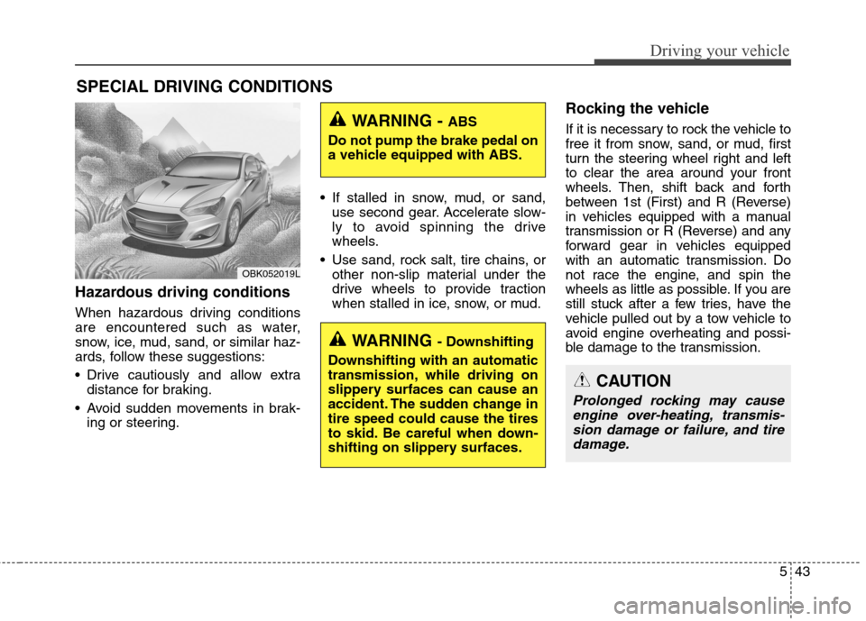
Hazardous driving conditions
When hazardous driving conditions
are encountered such as water,
snow, ice, mud, sand, or similar haz-
ards, follow these suggestions:
Drive cautiously and allow extra
distance for braking.
Avoid sudden movements in brak-
ing or steering. If stalled in snow, mud, or sand,
use second gear. Accelerate slow-
ly to avoid spinning the drive
wheels.
Use sand, rock salt, tire chains, or
other non-slip material under the
drive wheels to provide traction
when stalled in ice, snow, or mud.
Rocking the vehicle
If it is necessary to rock the vehicle to
free it from snow, sand, or mud, first
turn the steering wheel right and left
to clear the area around your front
wheels. Then, shift back and forth
between 1st (First) and R (Reverse)
in vehicles equipped with a manual
transmission or R (Reverse) and any
forward gear in vehicles equipped
with an automatic transmission. Do
not race the engine, and spin the
wheels as little as possible. If you are
still stuck after a few tries, have the
vehicle pulled out by a tow vehicle to
avoid engine overheating and possi-
ble damage to the transmission.
SPECIAL DRIVING CONDITIONS
WARNING - ABS
Do not pump the brake pedal on
a vehicle equipped with ABS.
WARNING - Downshifting
Downshifting with an automatic
transmission, while driving on
slippery surfaces can cause an
accident. The sudden change in
tire speed could cause the tires
to skid. Be careful when down-
shifting on slippery surfaces.
CAUTION
Prolonged rocking may cause
engine over-heating, transmis-
sion damage or failure, and tire
damage.
OBK052019L
Page 323 of 438
615
What to do in an emergency
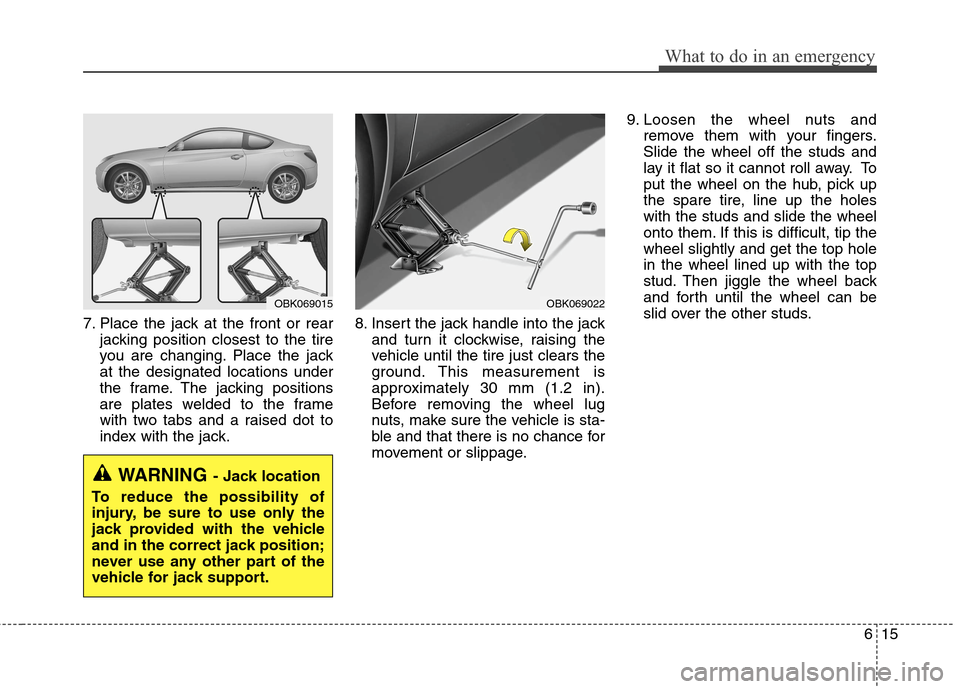
7. Place the jack at the front or rear
jacking position closest to the tire
you are changing. Place the jack
at the designated locations under
the frame. The jacking positions
are plates welded to the frame
with two tabs and a raised dot to
index with the jack.8. Insert the jack handle into the jack
and turn it clockwise, raising the
vehicle until the tire just clears the
ground. This measurement is
approximately 30 mm (1.2 in).
Before removing the wheel lug
nuts, make sure the vehicle is sta-
ble and that there is no chance for
movement or slippage.9. Loosen the wheel nuts and
remove them with your fingers.
Slide the wheel off the studs and
lay it flat so it cannot roll away. To
put the wheel on the hub, pick up
the spare tire, line up the holes
with the studs and slide the wheel
onto them. If this is difficult, tip the
wheel slightly and get the top hole
in the wheel lined up with the top
stud. Then jiggle the wheel back
and forth until the wheel can be
slid over the other studs.
WARNING- Jack location
To reduce the possibility of
injury, be sure to use only the
jack provided with the vehicle
and in the correct jack position;
never use any other part of the
vehicle for jack support.
OBK069022OBK069015
Page 378 of 438
Maintenance
46 7
Compact spare tire replacement
(if equipped)
A compact spare tire has a shorter
tread life than a regular size tire.
Replace it when you can see the
tread wear indicator bars on the tire.
The replacement compact spare tire
should be the same size and design
tire as the one provided with your
new vehicle and should be mounted
on the same compact spare tire
wheel. The compact spare tire is not
designed to be mounted on a regular
size wheel, and the compact spare
tire wheel is not designed for mount-
ing a regular size tire.
Wheel replacement
When replacing the metal wheels for
any reason, make sure the new
wheels are equivalent to the original
factory units in diameter, rim width
and offset.
✽ ✽
NOTICE
The front tire size is different from
the rear tire size. So when you rotate
tires, check the tire and wheel size.
(Continued)
Using tires and wheel other
than the recommended sizes
could cause unusual handling
characteristics and poor vehi-
cle control, resulting in a seri-
ous accident.
Wheels that do not meet
HYUNDAI’s specifications
may fit poorly and result in
damage to the vehicle or
unusual handling and poor
vehicle control.
The ABS works by comparing
the speed of the wheels. Tire
size can affect wheel speed.
When replacing tires, all 4
tires must use the size origi-
nally supplied with the vehi-
cle. Using tires of a different
size can cause the ABS (Anti-
lock Brake System) and ESC
(Electronic Stability Control)
to work irregularly.
WARNING
A wheel that is not the correct
size may adversely affect wheel
and bearing life, braking and
stopping abilities, handling
characteristics, ground clear-
ance, body-to-tire clearance,
snow chain clearance,
speedometer and odometer cal-
ibration, headlight aim and
bumper height.
Page 394 of 438
Maintenance
62 7
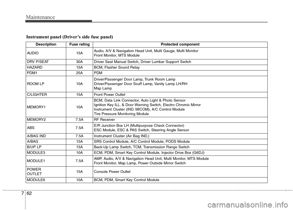
Instrument panel (Driver’s side fuse panel)
Description Fuse rating Protected component
AUDIO 15AAudio, A/V & Navigation Head Unit, Multi Gauge, Multi Monitor
Front Monitor, MTS Module
DRV P/SEAT 30A Driver Seat Manual Switch, Driver Lumbar Support Switch
HAZARD 15A BCM, Flasher Sound Relay
PDM1 25A PDM
ROOM LP 10ADriver/Passenger Door Lamp, Trunk Room Lamp
Driver/Passenger Door Scuff Lamp, Vanity Lamp LH/RH
Map Lamp
C/LIGHTER 15A Front Power Outlet
MEMORY1 10ABCM, Data Link Connector, Auto Light & Photo Sensor
Ignition Key ILL. & Door Warning Switch, Electro Chromic Mirror
Instrument Cluster (IND. MICOM), A/C Control Module
Tire Pressure Monitoring Module
MEMORY2 7.5A RF Receiver
ABS 7.5AE/R Junction Box LH (Multipurpose Check Connector)
ESC Module, ESC & PAS Switch, Steering Angle Sensor
A/BAG IND 7.5A Instrument Cluster (Air Bag IND.)
A/BAG 15A SRS Control Module, A/C Control Module, PODS Module
B/UP LP 15A Back-Up Lamp Switch, TCM, Transmission Range Switch
MODULE3 10A ECM, PDM, Smart Key Control Module, Injector Drive Box (G6DJ)
MODULE1 7.5AAMP, Audio, A/V & Navigation Head Unit, Multi Monitor, MTS Module
Front Monitor, Map Lamp, Power Outside Mirror Switch
POWER
OUTLET15A Console Power Outlet
MODULE6 10A BCM, PDM, Smart Key Control Module
Page 396 of 438
Maintenance
64 7
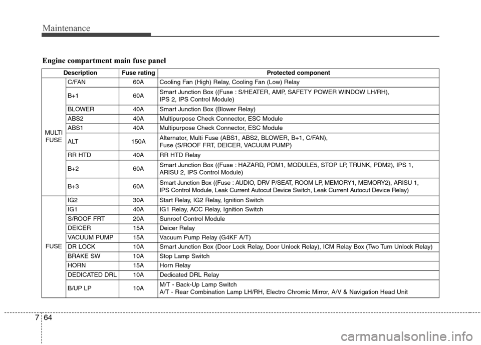
Engine compartment main fuse panel
Description Fuse rating Protected component
MULTI
FUSEC/FAN 60A Cooling Fan (High) Relay, Cooling Fan (Low) Relay
B+1 60ASmart Junction Box ((Fuse : S/HEATER, AMP, SAFETY POWER WINDOW LH/RH),
IPS 2, IPS Control Module)
BLOWER 40A Smart Junction Box (Blower Relay)
ABS2 40A Multipurpose Check Connector, ESC Module
ABS1 40A Multipurpose Check Connector, ESC Module
ALT 150AAlternator, Multi Fuse (ABS1, ABS2, BLOWER, B+1, C/FAN),
Fuse (S/ROOF FRT, DEICER, VACUUM PUMP)
RR HTD 40A RR HTD Relay
B+260ASmart Junction Box ((Fuse : HAZARD, PDM1, MODULE5, STOP LP, TRUNK, PDM2), IPS 1,
ARISU 2, IPS Control Module)
B+360ASmart Junction Box ((Fuse : AUDIO, DRV P/SEAT, ROOM LP, MEMORY1, MEMORY2), ARISU 1,
IPS Control Module, Leak Current Autocut Device Switch, Leak Current Autocut Device Relay)
FUSEIG2 30A Start Relay, IG2 Relay, Ignition Switch
IG140AIG1 Relay, ACC Relay, Ignition Switch
S/ROOF FRT 20A Sunroof Control Module
DEICER 15A Deicer Relay
VACUUM PUMP 15A Vacuum Pump Relay (G4KF A/T)
DR LOCK 10A Smart Junction Box (Door Lock Relay, Door Unlock Relay), ICM Relay Box (Two Turn Unlock Relay)
BRAKE SW 10A Stop Lamp Switch
HORN 15A Horn Relay
DEDICATED DRL 10A Dedicated DRL Relay
B/UP LP 10AM/T - Back-Up Lamp Switch
A/T - Rear Combination Lamp LH/RH, Electro Chromic Mirror, A/V & Navigation Head Unit
Page 402 of 438
Maintenance
70 7
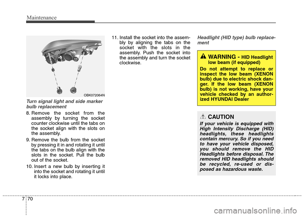
Turn signal light and side marker
bulb replacement
8. Remove the socket from the
assembly by turning the socket
counter clockwise until the tabs on
the socket align with the slots on
the assembly.
9. Remove the bulb from the socket
by pressing it in and rotating it until
the tabs on the bulb align with the
slots in the socket. Pull the bulb
out of the socket.
10. Insert a new bulb by inserting it
into the socket and rotating it until
it locks into place.11. Install the socket into the assem-
bly by aligning the tabs on the
socket with the slots in the
assembly. Push the socket into
the assembly and turn the socket
clockwise.
Headlight (HID type) bulb replace-
ment
WARNING - HID Headlight
low beam (if equipped)
Do not attempt to replace or
inspect the low beam (XENON
bulb) due to electric shock dan-
ger. If the low beam (XENON
bulb) is not working, have your
vehicle checked by an author-
ized HYUNDAI Dealer
OBK072064N
CAUTION
If your vehicle is equipped with
High Intensity Discharge (HID)
headlights, these headlights
contain mercury. So if you need
to have your vehicle disposed,
you should remove the HID
Headlights before disposal. The
removed HID headlights should
be recycled, re-used or dis-
posed as hazardous waste.
Page 403 of 438
771
Maintenance
✽ ✽
NOTICE
HID lamps have superior perform-
ance vs. halogen bulbs. HID lamps
are estimated by the manufacturer to
last twice as long or longer than halo-
gen bulbs depending on their fre-
quency of use. They will probably
require replacement at some point in
the life of the vehicle. Cycling the
headlamps on and off more than typ-
ical use will shorten HID lamps life.
HID lamps do not fail in the same
manner as halogen incandescent
lamps. If a headlamp goes out after a
period of operation but will immedi-
ately relight when the headlamp
switch is cycled it is likely the HID
lamp needs to be replaced. HID light-
ing components are more complex
than conventional halogen bulbs thus
have higher replacement cost.
If the light bulb is not operating, have
the vehicle checked by an authorized
HYUNDAI dealer.
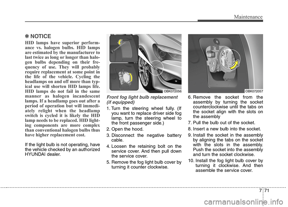
Front fog light bulb replacement
(if equipped)
1. Turn the steering wheel fully. (If
you want to replace driver side fog
lamp, turn the steering wheel to
the front passenger side.)
2. Open the hood.
3. Disconnect the negative battery
cable.
4. Loosen the retaining bolt on the
service cover. And then pull down
the service cover.
5. Remove the fog light bulb cover by
turning it counter clockwise.6. Remove the socket from the
assembly by turning the socket
counterclockwise until the tabs on
the socket align with the slots on
the assembly
7. Pull the bulb out of the socket.
8. Insert a new bulb into the socket.
9. Install the socket in the assembly
by aligning the tabs on the socket
with the slots in the assembly.
Push the socket into the assembly
and turn the socket clockwise.
10. Install the fog light bulb cover by
turning it clockwise. And then
assemble the service cover.
OBK072056OBK072057
Page 405 of 438
773
Maintenance
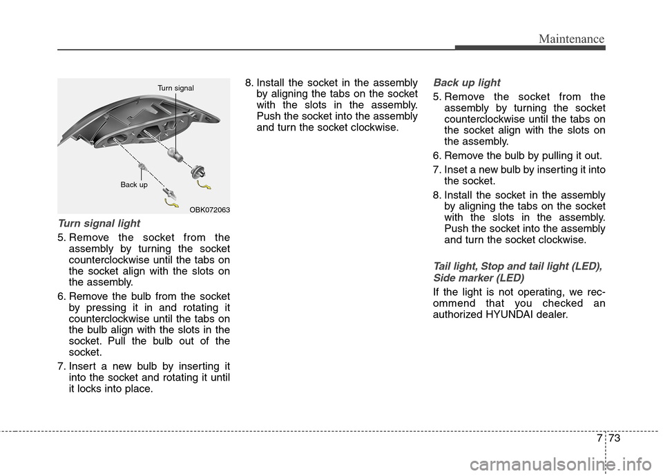
Turn signal light
5. Remove the socket from the
assembly by turning the socket
counterclockwise until the tabs on
the socket align with the slots on
the assembly.
6. Remove the bulb from the socket
by pressing it in and rotating it
counterclockwise until the tabs on
the bulb align with the slots in the
socket. Pull the bulb out of the
socket.
7. Insert a new bulb by inserting it
into the socket and rotating it until
it locks into place.8. Install the socket in the assembly
by aligning the tabs on the socket
with the slots in the assembly.
Push the socket into the assembly
and turn the socket clockwise.
Back up light
5. Remove the socket from the
assembly by turning the socket
counterclockwise until the tabs on
the socket align with the slots on
the assembly.
6. Remove the bulb by pulling it out.
7. Inset a new bulb by inserting it into
the socket.
8. Install the socket in the assembly
by aligning the tabs on the socket
with the slots in the assembly.
Push the socket into the assembly
and turn the socket clockwise.
Tail light, Stop and tail light (LED),
Side marker (LED)
If the light is not operating, we rec-
ommend that you checked an
authorized HYUNDAI dealer.
OBK072063 Back up Turn signal