turn signal HYUNDAI GENESIS G80 2013 Owners Manual
[x] Cancel search | Manufacturer: HYUNDAI, Model Year: 2013, Model line: GENESIS G80, Model: HYUNDAI GENESIS G80 2013Pages: 432, PDF Size: 29.24 MB
Page 14 of 432
17
Introduction
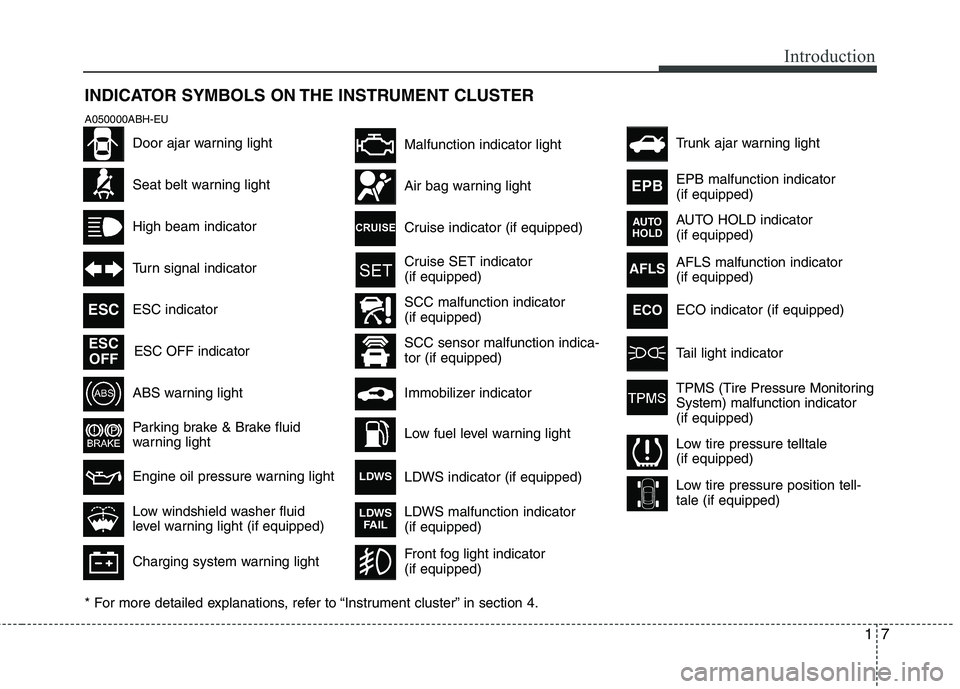
INDICATOR SYMBOLS ON THE INSTRUMENT CLUSTER
Seat belt warning light
High beam indicator
Turn signal indicator
ABS warning light
Parking brake & Brake fluid
warning light
Engine oil pressure warning light ESC indicator
ESC OFF indicator
Malfunction indicator light
Air bag warning light
Cruise indicator (if equipped)
Cruise SET indicator
(if equipped)
Immobilizer indicator
Low fuel level warning light
* For more detailed explanations, refer to “Instrument cluster” in section 4.
Charging system warning light
Low windshield washer fluid
level warning light (if equipped)
A050000ABH-EU
Door ajar warning light
AFLS malfunction indicator
(if equipped)
Tail light indicator
Trunk ajar warning light
Front fog light indicator
(if equipped)
ESC
ESC
OFF
AFLS
ECO
TPMS (Tire Pressure Monitoring
System) malfunction indicator
(if equipped)
Low tire pressure telltale
(if equipped)
Low tire pressure position tell-
tale (if equipped)
SCC malfunction indicator
(if equipped)
SCC sensor malfunction indica-
tor (if equipped)EPB malfunction indicator
(if equipped)
AUTO HOLD indicator
(if equipped)
EPB
AUTO
HOLD
LDWS indicator (if equipped)LDWS
LDWS malfunction indicator
(if equipped)LDWS
FAIL
ECO indicator (if equipped)
Page 16 of 432
Your vehicle at a glance
2 2
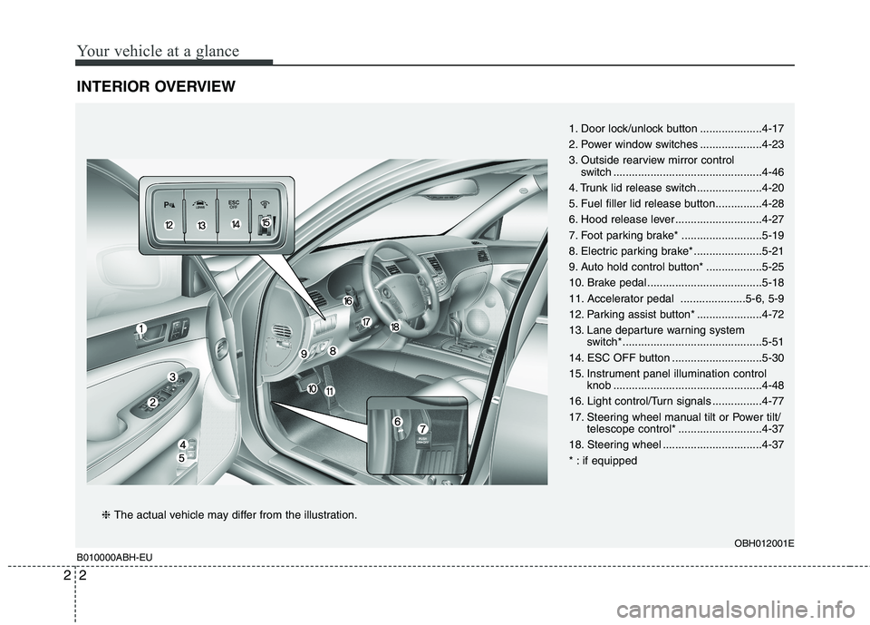
INTERIOR OVERVIEW
B010000ABH-EUOBH012001E
1. Door lock/unlock button ....................4-17
2. Power window switches ....................4-23
3. Outside rearview mirror control
switch ................................................4-46
4. Trunk lid release switch .....................4-20
5. Fuel filler lid release button...............4-28
6. Hood release lever ............................4-27
7. Foot parking brake* ..........................5-19
8. Electric parking brake* ......................5-21
9. Auto hold control button* ..................5-25
10. Brake pedal .....................................5-18
11. Accelerator pedal .....................5-6, 5-9
12. Parking assist button* .....................4-72
13. Lane departure warning system
switch*.............................................5-51
14. ESC OFF button .............................5-30
15. Instrument panel illumination control
knob ................................................4-48
16. Light control/Turn signals ................4-77
17. Steering wheel manual tilt or Power tilt/
telescope control* ...........................4-37
18. Steering wheel ................................4-37
* : if equipped
❈ The actual vehicle may differ from the illustration.
Page 55 of 432
Safety features of your vehicle
36 3
C040900AEN-EU
How does the air bag system
operate
Air bags are activated (able to inflate if
necessary) only when the ignition
switch is turned to the ON or START
position.
Air bags inflate in the event of a seri-
ous frontal or side collision in order to
help protect the occupants from seri-
ous physical injury.
There is no single speed at which the
air bags will inflate.
Generally, air bags are designed to
inflate based upon the severity of a col-
lision and its direction. These two fac-
tors determine whether the sensors
produce an electronic deployment/
inflation signal.
Air bag deployment depends on a
number of factors including vehicle
speed, angles of impact and the densi-
ty and stiffness of the vehicles or
objects which your vehicle hits in the
collision. The determining factors are
not limited to those mentioned above.
The front air bags will completely
inflate and deflate in an instant.
It is virtually impossible for you to see
the air bags inflate during an accident.It is much more likely that you will sim-
ply see the deflated air bags hanging
out of their storage compartments after
the collision.
In order to help provide protection in a
severe collision, the air bags must
inflate rapidly. The speed of air bag
inflation is a consequence of the
extremely short time in which a collision
occurs and the need to inflate the air
bag between the occupant and the
vehicle structures before the occupant
impacts those structures. This speed of
inflation reduces the risk of serious or
life-threatening injuries in a severe col-
lision and is thus a necessary part of air
bag design.
However, air bag inflation can also
cause injuries which can include facial
abrasions, bruises and broken bones
because the inflation speed also caus-
es the air bags to expand with a great
deal of force.
There are even circumstances
under which contact with the air bag
can cause fatal injuries, especially if
the occupant is positioned exces-
sively close to the air bag.
WARNING
To avoid severe personal injury
or death caused by deploying air
bags in a collision, the driver
should sit as far back from the
steering wheel air bag as possi-
ble (at least 10 inches (250 mm)
away). The front passengers
should always move their seats
as far back as possible and sit
back in their seat.
Air bags inflate instantly in the
event of collision, and passen-
gers may be injured by the air bag
expansion force if they are not in
proper position.
Air bag inflation may cause
injuries including facial or bodily
abrasions, injuries from broken
glasses or burns.
Page 121 of 432
Features of your vehicle
42 4
1. Press and hold the button for more
than 9 seconds. When the compass
memory is cleared a "C" will appear in
the display.
2. To calibrate the compass, drive the
vehicle in 2 complete circles at less
than 5 mph (8 km/h).
Integrated HomeLink
®Wireless Control
System
The HomeLink
®Wireless Control System
provides a convenient way to replace up
to three hand-held radio-frequency (RF)
transmitters with a single built-in device.
This innovative feature will learn the
radio frequency codes of most current
transmitters to operate devices such as
gate operators, garage door openers,
entry door locks, security systems, even
home lighting. Both standard and rolling
code-equipped transmitters can be pro-
grammed by following the outlined proce-
dures. Additional HomeLink
®information
can be found at: www.homelink.com or
by calling 1-800-355-3515.Retain the original transmitter of the RF
device you are programming for use in
other vehicles as well as for future
HomeLink
®programming. It is also sug-
gested that upon the sale of the vehicle,
the programmed HomeLink
®buttons be
erased for security purposes.Programming HomeLink
®
✽ ✽
NOTICE
• When programming a garage door
opener, it is advised to park the vehi-
cle outside of the garage.
• It is recommended that a new battery
be placed in the hand-held transmit-
ter of the device being programmed to
HomeLink
®for quicker training and
accurate transmission of the radio-
frequency signal.
• Some vehicles may require the igni-
tion switch to be turned to the second
(or "accessories") position for pro-
gramming and/or operation of
HomeLink.
• In the event that there are still pro-
gramming difficulties or questions
after following the programming steps
listed below, contact HomeLink
®at:
www.homelink.com or 1-800-355-
3515.
WARNING
Before programming HomeLink®to
a garage door opener or gate oper-
ator, make sure that people and
objects are out of the way of the
device to prevent potential harm or
damage. Do not use HomeLink
®
with any garage door opener that
lacks the safety stop and reverse
features required by U.S. federal
safety standards (this includes any
garage door opener model manu-
factured before April 1, 1982). A
garage door that cannot detect an
object - signaling the door to stop
and reverse - does not meet current
U.S. federal safety standards. Using
a garage door opener without these
features increases the risk of seri-
ous injury or death.
Page 123 of 432
Features of your vehicle
44 4
5. At the garage door opener receiver
(motor-head unit) in the garage, locate
the "leam" or "smart" button. This can
usually be found where the hanging
antenna wire is attached to the motor-
head unit.
6. Firmly press and release the "leam" or
"smart" button. (The name and color of
the button vary by manufacturer).
There are 30 seconds to initiate step
7.
7. Return to the vehicle and firmly press,
hold for 2 seconds
and release the programmed
HomeLink
®button. Repeat the
"press/hold/release" sequence a sec-
ond time, and, depending on the brand
of the garage door opener (or other
rolling code equipped device), repeat
this sequence a third time to complete
the programming process.
HomeLink
®should now activate your
rolling code equipped device.Gate operator & Canadian program-
ming
During programming, your handheld
transmitter may automatically stop trans-
mitting. Continue to press the Integrated
HomeLink
®Wireless Control System but-
ton (note steps 2 through 3 in the
Programming portion of this document)
while you press and re-press ("cycle")
your handheld transmitter every two sec-
onds until the frequency signal has been
learned. The indicator light will flash
slowly and then rapidly after several sec-
onds upon successful training.
Operating HomeLink
®
To operate, simply press and release the
programmed HomeLink®button.
Activation will now occur for the trained
device (i.e. garage door opener, gate
operator, security system, entry door
lock, home/office lighting, etc.). For con-
venience, the hand-held transmitter of
the device may also be used at any time.Reprogramming a single HomeLink
®
button
To program a device to HomeLink®using
a HomeLink®button previously trained,
follow these steps:
1. Press and hold the desired HomeLink
®
button. DO NOT release the button.
2. The indicator light will begin to flash
after 20 seconds. Without releasing
the HomeLink
®button, proceed with
"Programming" step 2.
For questions or comments, contact
HomeLink
®at www.homelink.comor 1-
800-355-3515.
Erasing HomeLink
®buttons
Individual buttons cannot be erased.
However, to erase all three programmed
buttons:
1. Press and hold the two outer
HomeLink
®buttons until the indicator
light begins to flashafter 10 seconds.
2. Release both buttons. Do not hold for
longer than 20 seconds.
The Integrated HomeLink
®Wireless
Control System is now in the training
(learn) mode and can be programmed at
any time following the appropriate steps
in the Programming sections above.
Page 127 of 432
Features of your vehicle
48 4
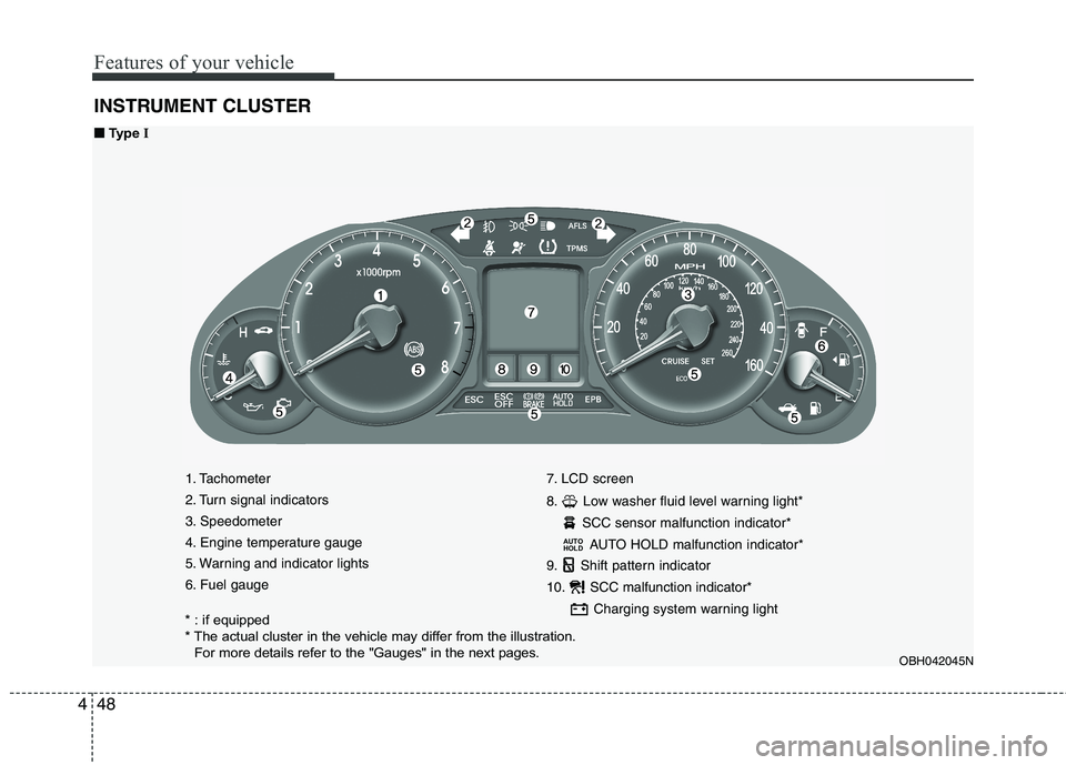
INSTRUMENT CLUSTER
1. Tachometer
2. Turn signal indicators
3. Speedometer
4. Engine temperature gauge
5. Warning and indicator lights
6. Fuel gauge7. LCD screen
8. Low washer fluid level warning light*
SCC sensor malfunction indicator*
AUTO HOLD malfunction indicator*
9. Shift pattern indicator
10. SCC malfunction indicator*
Charging system warning light
AUTO
HOLD
OBH042045N
■ ■
Type I
* : if equipped
* The actual cluster in the vehicle may differ from the illustration.
For more details refer to the "Gauges" in the next pages.
Page 128 of 432
449
Features of your vehicle
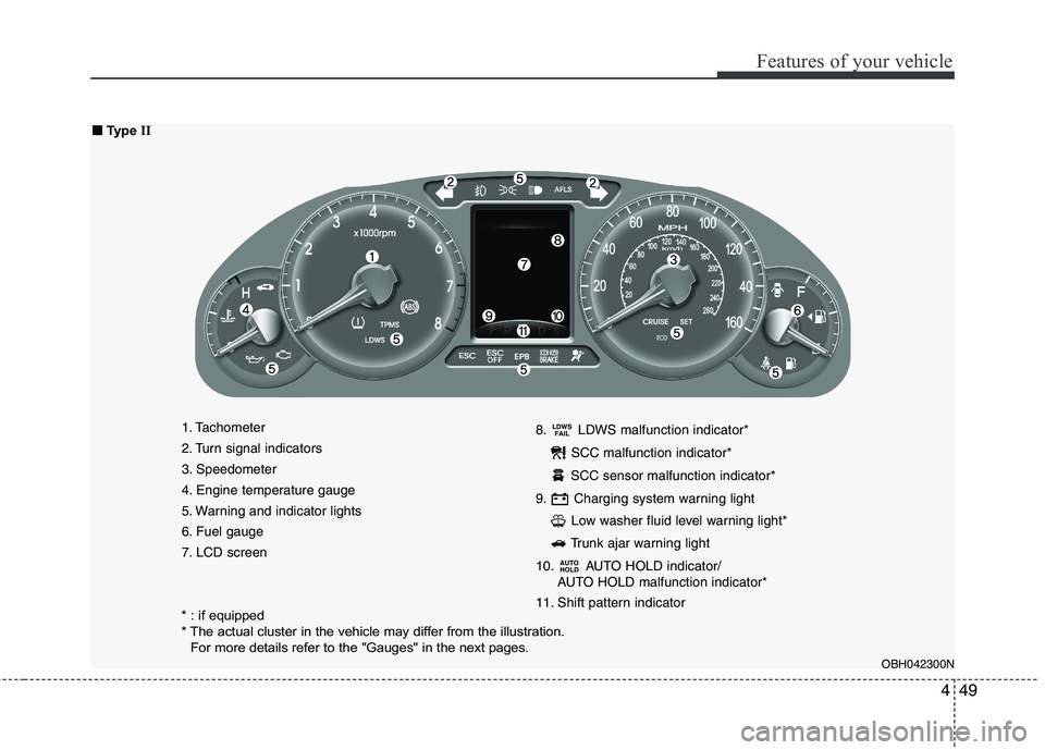
1. Tachometer
2. Turn signal indicators
3. Speedometer
4. Engine temperature gauge
5. Warning and indicator lights
6. Fuel gauge
7. LCD screen8. LDWS malfunction indicator*
SCC malfunction indicator*
SCC sensor malfunction indicator*
9. Charging system warning light
Low washer fluid level warning light*
Trunk ajar warning light
10. AUTO HOLD indicator/
AUTO HOLD malfunction indicator*
11. Shift pattern indicator
AUTO
HOLD
LDWS
FAIL
OBH042300N
■ ■
Type II
* : if equipped
* The actual cluster in the vehicle may differ from the illustration.
For more details refer to the "Gauges" in the next pages.
Page 139 of 432
Features of your vehicle
60 4
D150304CBH-EU
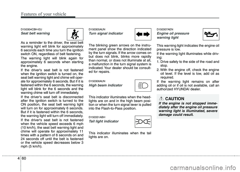
Seat belt warning
As a reminder to the driver, the seat belt
warning light will blink for approximately
6 seconds each time you turn the ignition
switch ON, regardless of belt fastening.
The warning light will blink again for
approximately 6 seconds when starting
the engine.
If the driver's seat belt is not fastened
when the ignition switch is turned on, the
seat belt warning light and chime will oper-
ate for approximately 6 seconds. But if it is
fastened within the 6 seconds, the warning
light will blink for the 6 seconds and the
warning chime will turn off immediately.
If the driver's seat belt is disconnected
after the ignition switch is turned to the
ON position, the seat belt warning light
will turn on for approximately 6 seconds.
But if it is fastened within the 6 seconds,
the warning light will turn off immediately.
If the driver's seat belt is not fastened
when the vehicle speed exceeds 6 mph
(10 km/h), the seat belt warning light and
chime will operate for approximately 11
times with a pattern of 6 seconds on and
24 seconds off until the belt is fastened
or the vehicle speed decreases below 3
mph (5 km/h).
D150305AUN
Turn signal indicator
The blinking green arrows on the instru-
ment panel show the direction indicated
by the turn signals. If the arrow comes on
but does not blink, blinks more rapidly
than normal, or does not illuminate at all,
a malfunction in the turn signal system is
indicated. Your dealer should be consult-
ed for repairs.
D150306AUN
High beam indicator
This indicator illuminates when the head-
lights are on and in the high beam posi-
tion or when the turn signal lever is pulled
into the Flash-to-Pass position.
D150331ABH
Tail light indicator
This indicator illuminates when the tail
lights are on.
D150307AEN
Engine oil pressure
warning light
This warning light indicates the engine oil
pressure is low.
If the warning light illuminates while driv-
ing:
1. Drive safely to the side of the road and
stop.
2. With the engine off, check the engine
oil level. If the level is low, add oil as
required.
If the warning light remains on after
adding oil or if oil is not available, call an
authorized HYUNDAI dealer.
CAUTION
If the engine is not stopped imme-
diately after the engine oil pressure
warning light is illuminated, severe
damage could result.
Page 155 of 432
Features of your vehicle
76 4
REAR VIEW CAMERA (IF EQUIPPED)
D330000ABH
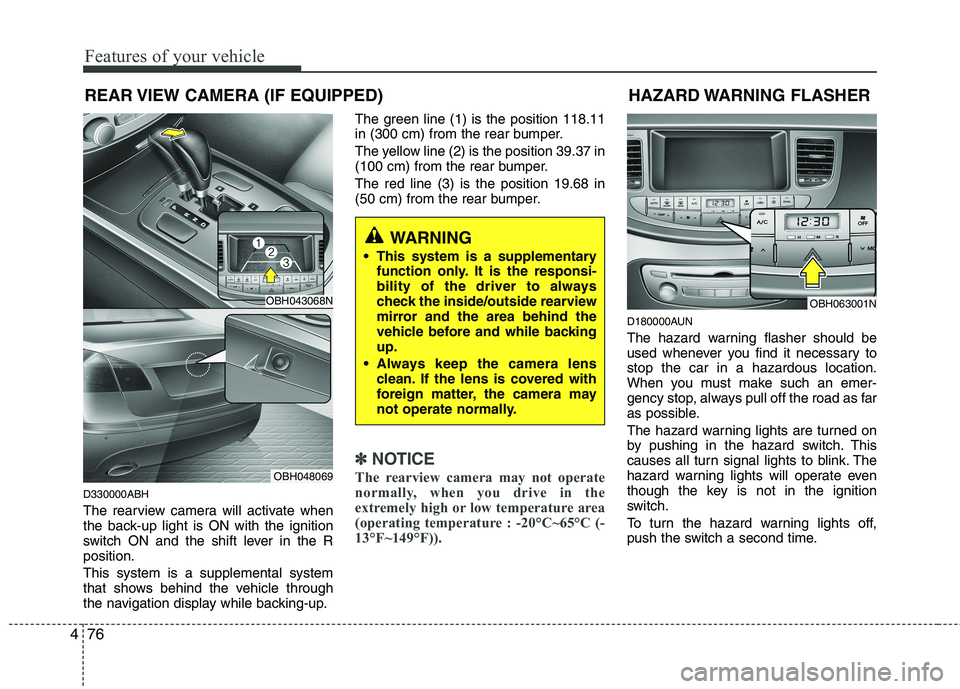
The rearview camera will activate when
the back-up light is ON with the ignition
switch ON and the shift lever in the R
position.
This system is a supplemental system
that shows behind the vehicle through
the navigation display while backing-up.The green line (1) is the position 118.11
in (300 cm) from the rear bumper.
The yellow line (2) is the position 39.37 in
(100 cm) from the rear bumper.
The red line (3) is the position 19.68 in
(50 cm) from the rear bumper.
✽ ✽
NOTICE
The rearview camera may not operate
normally, when you drive in the
extremely high or low temperature area
(operating temperature : -20°C~65°C (-
13°F~149°F)).
D180000AUN
The hazard warning flasher should be
used whenever you find it necessary to
stop the car in a hazardous location.
When you must make such an emer-
gency stop, always pull off the road as far
as possible.
The hazard warning lights are turned on
by pushing in the hazard switch. This
causes all turn signal lights to blink. The
hazard warning lights will operate even
though the key is not in the ignition
switch.
To turn the hazard warning lights off,
push the switch a second time.
HAZARD WARNING FLASHER
OBH063001N
WARNING
This system is a supplementary
function only. It is the responsi-
bility of the driver to always
check the inside/outside rearview
mirror and the area behind the
vehicle before and while backing
up.
Always keep the camera lens
clean. If the lens is covered with
foreign matter, the camera may
not operate normally.
OBH043068N
OBH048069
Page 159 of 432
Features of your vehicle
80 4
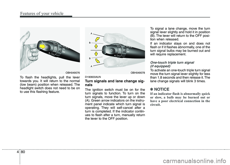
To flash the headlights, pull the lever
towards you. It will return to the normal
(low beam) position when released. The
headlight switch does not need to be on
to use this flashing feature.D190600AUN
Turn signals and lane change sig-
nals
The ignition switch must be on for the
turn signals to function. To turn on the
turn signals, move the lever up or down
(A). Green arrow indicators on the instru-
ment panel indicate which turn signal is
operating. They will self-cancel after a
turn is completed. If the indicator contin-
ues to flash after a turn, manually return
the lever to the OFF position.To signal a lane change, move the turn
signal lever slightly and hold it in position
(B). The lever will return to the OFF posi-
tion when released.
If an indicator stays on and does not
flash or if it flashes abnormally, one of the
turn signal bulbs may be burned out and
will require replacement.
One-touch triple turn signal
(if equipped)
To activate an one-touch triple turn signal
move the turn signal lever slightly for less
than 1.8 seconds and then release it. The
lane change signals will blink 3 times.
✽ ✽
NOTICE
If an indicator flash is abnormally quick
or slow, a bulb may be burned out or
have a poor electrical connection in the
circuit.
OBH049078OBH049076