Power steering Hyundai Getz 2003 Owner's Guide
[x] Cancel search | Manufacturer: HYUNDAI, Model Year: 2003, Model line: Getz, Model: Hyundai Getz 2003Pages: 444, PDF Size: 13.82 MB
Page 260 of 444
YOUR VEHICLE AT A GLANCE
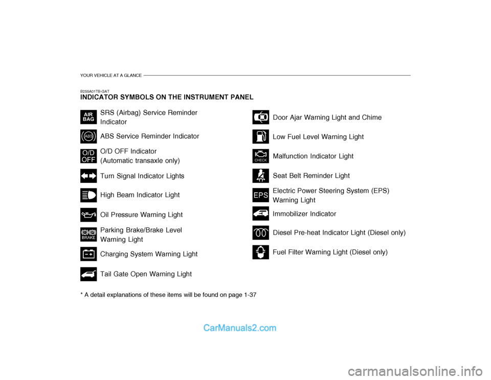
B255A01TB-GAT INDICATOR SYMBOLS ON THE INSTRUMENT PANEL * A detail explanations of these items will be found on page 1-37
SRS (Airbag) Service Reminder Indicator ABS Service Reminder Indicator Turn Signal Indicator Lights High Beam Indicator Light Oil Pressure Warning Light Parking Brake/Brake Level Warning Light Charging System Warning Light Tail Gate Open Warning LightDoor Ajar Warning Light and Chime
Low Fuel Level Warning Light Malfunction Indicator Light Seat Belt Reminder Light
O/D OFF Indicator (Automatic transaxle only)
Electric Power Steering System (EPS)Warning Light
Diesel Pre-heat Indicator Light (Diesel only)
Fuel Filter Warning Light (Diesel only)
Immobilizer Indicator
Page 295 of 444
FEATURES OF YOUR HYUNDAI 1- 35
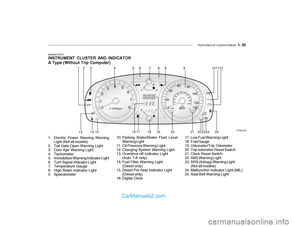
B260B02TB-EAT INSTRUMENT CLUSTER AND INDICATOR A Type (Without Trip Computer)
1. Electric Power Steering Warning Light (Not all models)
2. Tail Gate Open Warning Light
3. Door Ajar Warning Light
4. Tachometer
5. Immobilizer Warning Indicator Light
6. Turn Signal Indicator Light
7. Temperature Gauge
8. High Beam Indicator Light
9. Speedometer HTB001B
10. Parking Brake/Brake Fluid Level Warning Light
11. Oil Pressure Warning Light
12. Charging System Warning Light
13. Overdrive off Indicator Light (Auto T/A only)
14. Fuel Filter Warning Light (Diesel only)
15. Diesel Pre-heat Indicator Light (Diesel only)
16. Digital Clock 17. Low Fuel Warning Light
18. Fuel Gauge
19. Odometer/Trip Odometer
20. Trip odometer Reset Switch
21. Clock Reset Switch
22. ABS Warning Light
23. SRS (Airbag) Warning Light
(Not all models)
24. Malfunction Indicator Light (MIL)
25. Seat Belt Warning Light
1
2
4
53 6
7 8
9 1011
12
13 14
15 16
17 18
19 20 21
22
23 24
6
25
Page 296 of 444
1- 36 FEATURES OF YOUR HYUNDAI
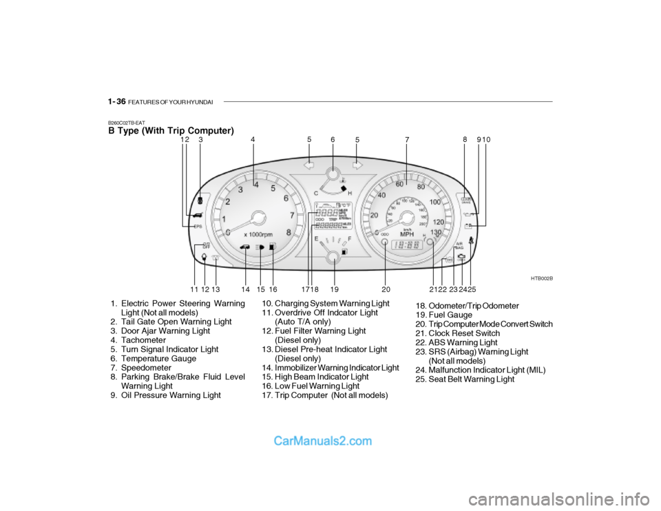
B260C02TB-EAT B Type (With Trip Computer)
1. Electric Power Steering Warning
Light (Not all models)
2. Tail Gate Open Warning Light
3. Door Ajar Warning Light
4. Tachometer
5. Turn Signal Indicator Light
6. Temperature Gauge
7. Speedometer
8. Parking Brake/Brake Fluid Level
Warning Light
9. Oil Pressure Warning Light HTB002B
10. Charging System Warning Light
11. Overdrive Off Indcator Light (Auto T/A only)
12. Fuel Filter Warning Light (Diesel only)
13. Diesel Pre-heat Indicator Light
(Diesel only)
14. Immobilizer Warning Indicator Light
15. High Beam Indicator Light
16. Low Fuel Warning Light
17. Trip Computer (Not all models) 18. Odometer/Trip Odometer
19. Fuel Gauge
20. Trip Computer Mode Convert Switch
21. Clock Reset Switch
22. ABS Warning Light
23. SRS (Airbag) Warning Light
(Not all models)
24. Malfunction Indicator Light (MIL)
25. Seat Belt Warning Light
12 3 4
5
5
6
78
910
11 12 13 14 15 16 17 18 19 20 22 23
242521
Page 300 of 444

1- 40 FEATURES OF YOUR HYUNDAI
B260S01B-GAT
DIESEL PRE-HEAT INDICATORLIGHT-AMBER(Diesel Engine)
The indicator light illuminates amber when the ignition switch is placed at the "ON" position. The engine can be started after the pre-heat indicator lightgoes off. The illuminating time varies with the water temperature, air tem- perature and battery condition. NOTE: If the engine were not started 10 seconds after the preheating is com-pleted, turn the ignition key once more to the "LOCK" position, and then to the "ON" position, in orderto preheat again.
B260T01TB-GAT
ELECTRIC POWER STEERING SYSTEM(EPS) WARNING LIGHT (Not all models)
This indicator light comes on about 4 seconds after the ignition key is turned to the "ON" position or after the engine is started, it will go out.This light also comes on when the EPS has some troubles. If it comes on while driving, have your vehicle inspected byan authorized Hyundai Dealer. B260E01HP-GAT
SEAT BELT WARNING LIGHT
The seat belt warning light blinks for about 6 seconds when the ignition key is turned from the "OFF" position to "ON" or "START".
CAUTION:
When you move the electric power steering back-end and forth-end continuously in stop position, steer- ing wheel plays heavily to operateanti-overload system. It is normal condition. It returns to be nomal getting time.!
B260U01TB-EAT IMMOBILIZER
INDICATOR LIGHT(Not all models)
This indicator light comes on for some seconds after the ignition key is turned to the "ON" position. At this time, youcan start the engine. The light goes out after the engine is running. In case this light goes out before you start the en-gine, you must turn to the "LOCK" position and restart the engine. In case this light blinks for five seconds whenthe ignition key is turned to "ON" posi- tion, this indicates that the immobilizer system is out of order. At this time,consult to the Hyundai dealer.
nearest authorized Hyundai dealer and have the system checked.
Page 374 of 444
3- 12 WHAT TO DO IN AN EMERGENCY
!
CAUTION:
The following restriction must be observed in order to avoid seriousdamage to the transaxle . The vehicle must never be towed from the rear with the front wheelson the ground. The vehicle must not be towed until transaxle fluid has been added tobring the level up to the "HOT" marking on the dipstick. (The level will need to be reduced again aftertowing). The vehicle must not be towed at speeds faster than 25 mph. or dis-tances greater than fifty miles. The general points regarding the steer- ing lock etc. described in the pre-ceding section (Manual transaxle vehicle) should be observed.
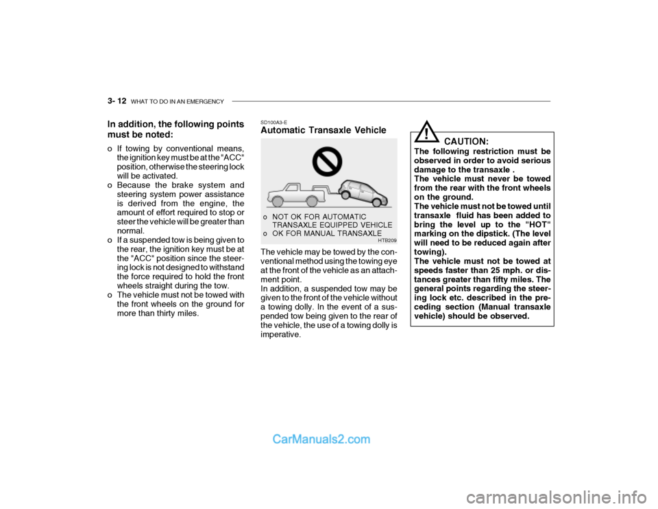
SD100A3-E Automatic Transaxle Vehicle The vehicle may be towed by the con- ventional method using the towing eye at the front of the vehicle as an attach- ment point.In addition, a suspended tow may be given to the front of the vehicle without a towing dolly. In the event of a sus-pended tow being given to the rear of the vehicle, the use of a towing dolly is imperative.
o NOT OK FOR AUTOMATIC
TRANSAXLE EQUIPPED VEHICLE
o OK FOR MANUAL TRANSAXLE HTB209
In addition, the following points must be noted:
o If towing by conventional means,
the ignition key must be at the "ACC" position, otherwise the steering lockwill be activated.
o Because the brake system and
steering system power assistanceis derived from the engine, the amount of effort required to stop or steer the vehicle will be greater thannormal.
o If a suspended tow is being given to
the rear, the ignition key must be atthe "ACC" position since the steer- ing lock is not designed to withstand the force required to hold the frontwheels straight during the tow.
o The vehicle must not be towed with
the front wheels on the ground formore than thirty miles.
Page 389 of 444

VEHICLE MAINTENANCE REQUIREMENTS 5- 9
6ZF070F1-A
o Brake hoses and lines
Visually check for proper installation, chafing, cracks, deterioration and any leakage. Replace any deteriorated or damaged parts immediately. 6ZF070G2-A
o Brake fluid
Check brake fluid level in the brake fluid reservoir. The level should bebetween "MIN" and "MAX" marks on the side of the reservoir. Use only hydraulic brake fluid conforming toDOT 3 or DOT 4. 6ZF070H1-A
o Rear brake drums and linings/ parking brake
Check the rear brake drums and lin- ings for scoring, burning, leaking fluid,broken parts, and excessive wear. Inspect the parking brake system in- cluding the parking brake lever andcables. For detailed service proce- dures, refer to the Shop Manual. 6ZF070J1-A
o Brake pads, calipers and
rotors
Check the pads for excessive wear,
discs for run out and wear, and cali- pers for fluid leakage.
6ZF070K1-A
o Exhaust pipe and muffler
Visually inspect the exhaust pipes,
muffler and hangers for cracks, dete- rioration, or damage. Start the engine and listen carefully for any exhaustgas leakage. Tighten connections or replace parts as necessary.
6ZF070L1-A
o Suspension mounting bolts
Check the suspension connections
for looseness or damage. Retightento the specified torque. 6ZF070M1-A o Steering gear box, linkage &
boots/lower arm ball joint
With the vehicle stopped and engine off, check for excessive freeplay inthe steering wheel.Check the linkage for bends or dam-age. Check the dust boots and ball joints for deterioration, cracks, or dam- age. Replace any damaged parts. 6ZF070N1-A
o Power steering pump, belt and hoses
Check the power steering pump and hoses for leakage and damage. Re-place any damaged or leaking parts immediately. Inspect the power steer- ing belt for evidence of cuts, cracks,excessive wear, oiliness and proper tension. Replace or adjust it if neces- sary.
Page 391 of 444

6. Do-It-Yourself Maintenance
Engine compartment ........................................................................ 6-2
Daily operating checks ..................................................................... 6-6
Engine oil .......................................................................................... 6-6
Engine and filter Replacement ......................................................... 6-9
Engine coolant Checking and Replacing .......................................6-10
Spark plug Replacement ................................................................ 6-13
Changing the air cleaner filter ......................................................... 6-14
Manual Transaxle Lubricant........................................................... 6-15
Automatic Transaxle fluid ............................................................... 6-16
Brake System Checking ................................................................ 6-18
Air conditioning System .................................................................. 6-19
Drive belts ...................................................................................... 6-23
Individual Circuit Fuses .................................................................. 6-24
Power steering fluid level ............................................................... 6-26
Replacing Light Bulbs .................................................................... 6-28
Fuse panel description ................................................................... 6-34
6
Page 392 of 444
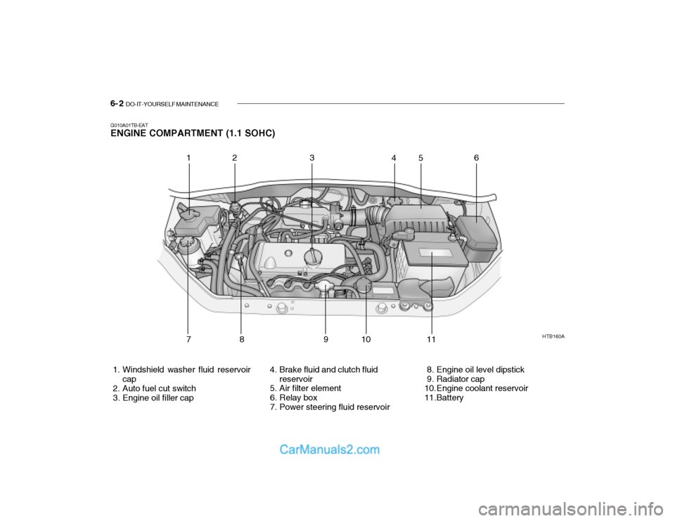
6- 2 DO-IT-YOURSELF MAINTENANCE
HTB160A
1. Windshield washer fluid reservoir cap
2. Auto fuel cut switch
3. Engine oil filler cap 4. Brake fluid and clutch fluid
reservoir
5. Air filter element
6. Relay box
7. Power steering fluid reservoir 8. Engine oil level dipstick
9. Radiator cap
10.Engine coolant reservoir
11.Battery
G010A01TB-EAT ENGINE COMPARTMENT (1.1 SOHC)
12 3
456
78 9 10 1 1
Page 393 of 444
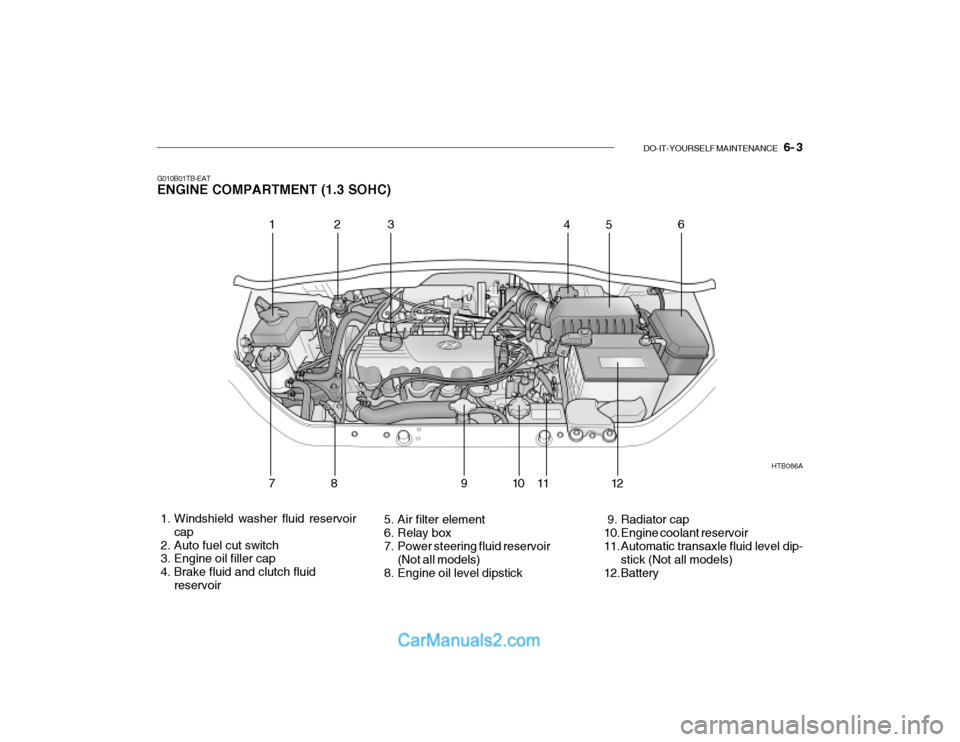
DO-IT-YOURSELF MAINTENANCE 6- 3
G010B01TB-EAT ENGINE COMPARTMENT (1.3 SOHC)
1. Windshield washer fluid reservoir
cap
2. Auto fuel cut switch
3. Engine oil filler cap
4. Brake fluid and clutch fluid reservoir 5. Air filter element
6. Relay box
7. Power steering fluid reservoir
(Not all models)
8. Engine oil level dipstick 9. Radiator cap
10. Engine coolant reservoir
11. Automatic transaxle fluid level dip-
stick (Not all models)
12. Battery HTB086A
123
456
78 91 011
12
Page 394 of 444
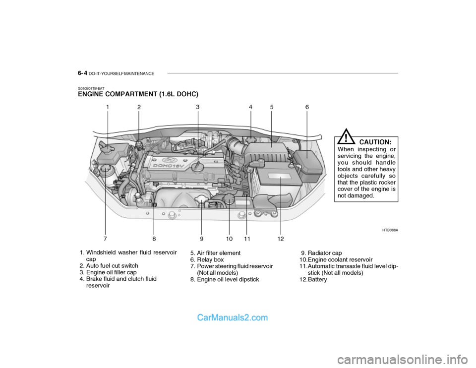
6- 4 DO-IT-YOURSELF MAINTENANCE
G010B01TB-EAT ENGINE COMPARTMENT (1.6L DOHC)
HTB088A
1. Windshield washer fluid reservoir cap
2. Auto fuel cut switch
3. Engine oil filler cap
4. Brake fluid and clutch fluid reservoir 5. Air filter element
6. Relay box
7. Power steering fluid reservoir
(Not all models)
8. Engine oil level dipstick 9. Radiator cap
10.Engine coolant reservoir
11.Automatic transaxle fluid level dip-
stick (Not all models)
12.Battery
1 2 34
56
789 10 11 12 CAUTION:
When inspecting or servicing the engine,you should handle tools and other heavy objects carefully sothat the plastic rocker cover of the engine is not damaged.
!