air filter Hyundai Getz 2004 Owner's Guide
[x] Cancel search | Manufacturer: HYUNDAI, Model Year: 2004, Model line: Getz, Model: Hyundai Getz 2004Pages: 445, PDF Size: 12.16 MB
Page 243 of 445
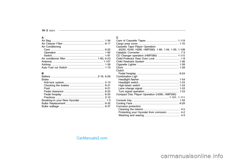
10- 2 INDEX
A Air Bag ...................................................................... 1-34
Air Cleaner Filter ....................................................... 6-17
Air Conditioning
Care ....................................................................... 6-22
Operation ............................................................... 1-82
Switch ..................................................................... 1-81
Air conditioner filter .......................................... 1-83, 6-23 Antenna ................................................................... 1-107
Ashtray ...................................................................... 1-58
Auto Fuel cut Switch................................................ 1-73
B
Battery .............................................................. 2-16, 6-28 Brake Anti-lock system ..................................................... 2-13
Checking the brakes .............................................. 6-21
Fluid ....................................................................... 6-21
Pedal clearance ..................................................... 6-25
Pedal freepl ay ........................................................ 6-25
Practices ................................................................ 2-12
Breaking-In your New Hyundai ................................... 1-3
Bulbs Repl acement ................................................... 6-32
Bulbs wattage ........................................................... 6-37C
Care of Cassette Tapes ....................
..................... 1-119
Cargo area cover ...................................................... 1-70
Cassette Tape Player Operation
(K220, K240, H280, HMP280) . 1-89, 1-94, 1-99, 1-108
Catalytic Converter ..................................................... 7-3
CD Changer operation (HMP280) .......................... 1-115
Child-Protector Rear Door Lock ................................. 1-8
Child Restraint System............................................. 1-26
Cigarette Lighter ....................................................... 1-58
Clock ......................................................................... 1-58
Clutch
Pedal freepl ay ........................................................ 6-24
Combination Ligh
Headlight flasher .................................................... 1-54
Headlight swi tch ..................................................... 1-53
High-beam swi tch .................................................. 1-54
Lane change si gnal ................................................ 1-53
Turn signal oper ation............................................. 1-53
Compact Disc Player Operation (H280, HMP280)
.................................................................. 1-101, 1-111
Console tray .............................................................. 1-59
Cooling Fans ............................................................. 6-29
Corrosion protection
Cleaning the interior ................................................. 4-5
Protecting your Hyundai from corrosion .................. 4-2
Washing and waxing ................................................ 4-3
Page 258 of 445
YOUR VEHICLE AT A GLANCE
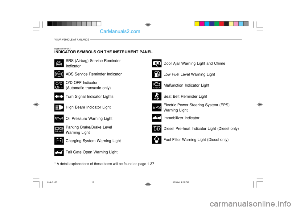
B255A01TB-GAT INDICATOR SYMBOLS ON THE INSTRUMENT PANEL * A detail explanations of these items will be found on page 1-37
SRS (Airbag) Service Reminder Indicator ABS Service Reminder Indicator Turn Signal Indicator Lights High Beam Indicator Light Oil Pressure Warning Light Parking Brake/Brake Level Warning Light Charging System Warning Light Tail Gate Open Warning LightDoor Ajar Warning Light and Chime
Low Fuel Level Warning Light Malfunction Indicator Light Seat Belt Reminder Light
O/D OFF Indicator (Automatic transaxle only)
Electric Power Steering System (EPS)Warning Light
Diesel Pre-heat Indicator Light (Diesel only)
Fuel Filter Warning Light (Diesel only)
Immobilizer Indicator
tbuk-0.p65
3/23/04, 4:21 PM
12
Page 295 of 445
FEATURES OF YOUR HYUNDAI 1- 37
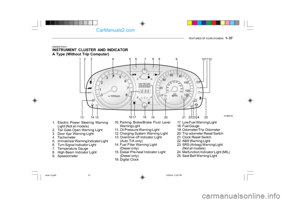
B260B02TB-EAT
INSTRUMENT CLUSTER AND INDICATOR
A Type (Without Trip Computer)
1. Electric Power Steering Warning Light (Not all models)
2. Tail Gate Open Warning Light
3. Door Ajar Warning Light
4. Tachometer
5. Immobilizer Warning Indicator Light
6. Turn Signal Indicator Light
7. Temperature Gauge
8. High Beam Indicator Light
9. Speedometer HTB001B
10. Parking Brake/Brake Fluid Level Warning Light
11. Oil Pressure Warning Light
12. Charging System Warning Light
13. Overdrive off Indicator Light (Auto T/A only)
14. Fuel Filter Warning Light (Diesel only)
15. Diesel Pre-heat Indicator Light (Diesel only)
16. Digital Clock 17. Low Fuel Warning Light
18. Fuel Gauge
19. Odometer/Trip Odometer
20. Trip odometer Reset Switch
21. Clock Reset Switch
22. ABS Warning Light
23. SRS (Airbag) Warning Light
(Not all models)
24. Malfunction Indicator Light (MIL)
25. Seat Belt Warning Light
1
2
4
53 6
7 8
9 1011
12
13 14
15 16
17 18
19 20 21
22
23 24
6
25
tbuk-1a.p65 3/23/04, 2:22 PM
37
Page 296 of 445
1- 38 FEATURES OF YOUR HYUNDAI
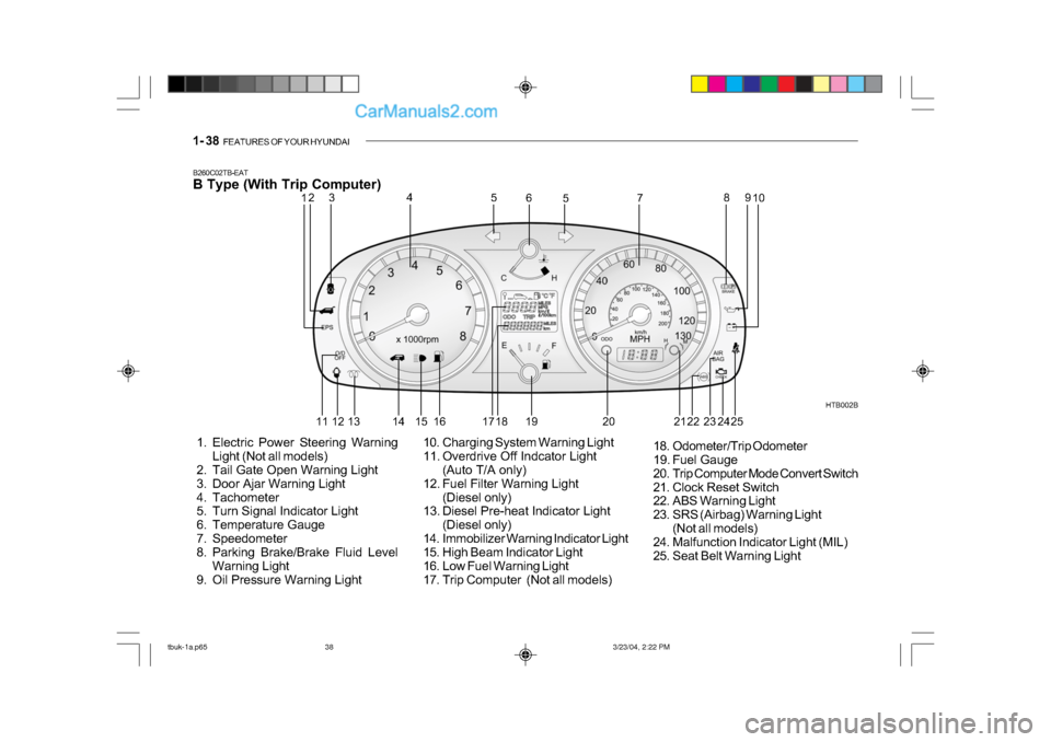
B260C02TB-EAT
B Type (With Trip Computer)
1. Electric Power Steering Warning
Light (Not all models)
2. Tail Gate Open Warning Light
3. Door Ajar Warning Light
4. Tachometer
5. Turn Signal Indicator Light
6. Temperature Gauge
7. Speedometer
8. Parking Brake/Brake Fluid Level
Warning Light
9. Oil Pressure Warning Light HTB002B
10. Charging System Warning Light
11. Overdrive Off Indcator Light (Auto T/A only)
12. Fuel Filter Warning Light (Diesel only)
13. Diesel Pre-heat Indicator Light
(Diesel only)
14. Immobilizer Warning Indicator Light
15. High Beam Indicator Light
16. Low Fuel Warning Light
17. Trip Computer (Not all models) 18. Odometer/Trip Odometer
19. Fuel Gauge
20. Trip Computer Mode Convert Switch
21. Clock Reset Switch
22. ABS Warning Light
23. SRS (Airbag) Warning Light
(Not all models)
24. Malfunction Indicator Light (MIL)
25. Seat Belt Warning Light
12 3 4
5
5
6
78
910
11 12 13 14 15 16 17 18 19 20 22 23
24 2521
tbuk-1a.p65 3/23/04, 2:22 PM
38
Page 337 of 445
FEATURES OF YOUR HYUNDAI 1- 79
!
B760A01Y
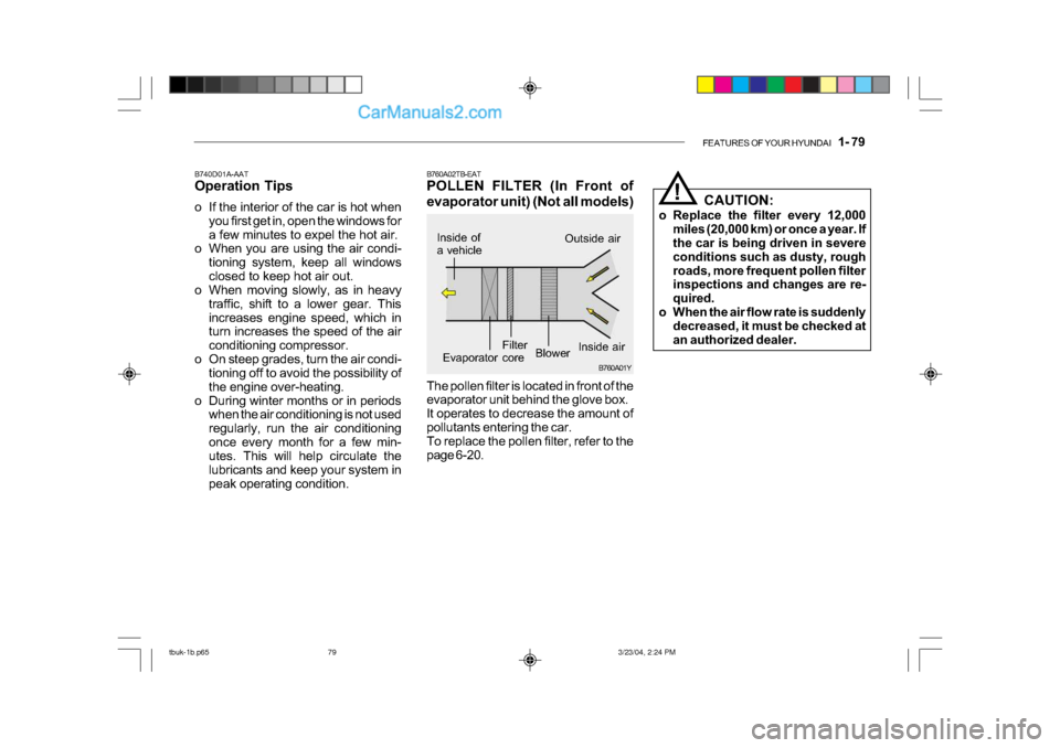
The pollen filter is located in front of the
evaporator unit behind the glove box.
It operates to decrease the amount of
pollutants entering the car.
To replace the pollen filter, refer to the
page 6-20.
B760A02TB-EAT
POLLEN FILTER (In Front of
evaporator unit) (Not all models)
B740D01A-AAT
Operation Tips
o If the interior of the car is hot when
you first get in, open the windows for
a few minutes to expel the hot air.
o When you are using the air condi-
tioning system, keep all windows
closed to keep hot air out.
o When moving slowly, as in heavy
traffic, shift to a lower gear. This
increases engine speed, which in
turn increases the speed of the air
conditioning compressor.
o On steep grades, turn the air condi- tioning off to avoid the possibility of
the engine over-heating.
o During winter months or in periods when the air conditioning is not used
regularly, run the air conditioning
once every month for a few min-
utes. This will help circulate the
lubricants and keep your system in
peak operating condition. Inside of
a vehicle
Evaporator core
Filter
BlowerOutside air
Inside air CAUTION:
o Replace the filter every 12,000 miles (20,000 km) or once a year. If
the car is being driven in severe
conditions such as dusty, rough
roads, more frequent pollen filter
inspections and changes are re-
quired.
o When the air flow rate is suddenly decreased, it must be checked at
an authorized dealer.
tbuk-1b.p65 3/23/04, 2:24 PM
79
Page 384 of 445
VEHICLE MAINTENANCE REQUIREMENTS 5- 3
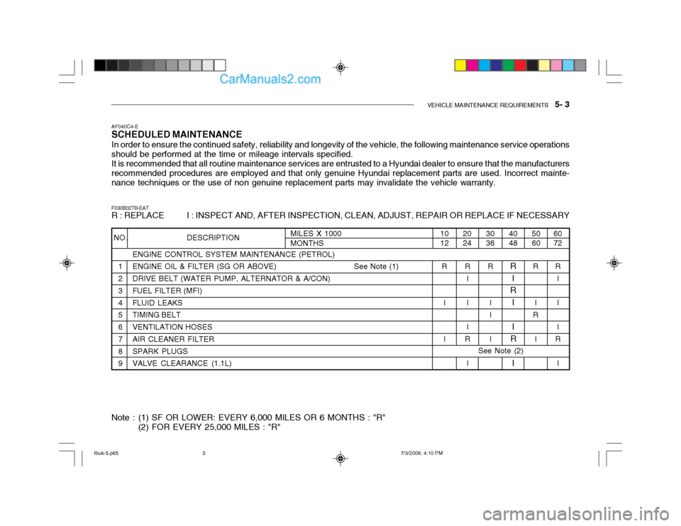
ENGINE CONTROL SYSTEM MAINTENANCE (PETROL)
1 ENGINE OIL & FILTER (SG OR ABOVE) See Note (1)
2 DRIVE BELT (WATER PUMP, ALTERNATOR & A/CON)
3 FUEL FILTER (MFI)
4 FLUID LEAKS
5 TIMING BELT
6 VENTILATION HOSES
7 AIR CLEANER FILTER
8 SPARK PLUGS
9 VALVE CLEARANCE (1.1L)
AF040C4-E
SCHEDULED MAINTENANCE
In order to ensure the continued safety, reliability and longevity of the vehicle, the following maintenance service operations should be performed at the time or mileage intervals specified. It is recommended that all routine maintenance services are entrusted to a Hyundai dealer to ensure that the manufacturers recommended procedures are employed and that only genuine Hyundai replacement parts are used. Incorrect mainte- nance techniques or the use of non genuine replacement parts may invalidate the vehicle warranty. F030B02TB-EAT R : REPLACE I : INSPECT AND, AFTER INSPECTION, CLEAN, ADJUST, REPAIR OR REPLACE IF NECESSARY
Note : (1) SF OR LOWER: EVERY 6,000 MILES OR 6 MONTHS : "R" (2) FOR EVERY 25,000 MILES : "R"
NO. DESCRIPTION60 72
5060
4048
3036
2024
1012
MILES X 1000 MONTHS
R
I II
R
I
R
I
R
I
R
I
R
I
I
R
I
R
I I I
R
III
R
I
R
I I
See Note (2)
tbuk-5.p65 7/3/2008, 4:10 PM
3
Page 385 of 445
5- 4 VEHICLE MAINTENANCE REQUIREMENTS
F030D02B-EAT
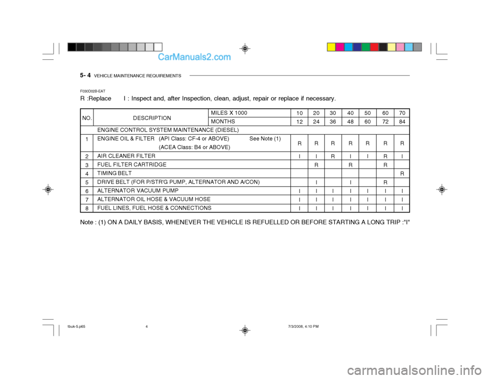
R :Replace I : Inspect and, after Inspection, clean, adjust, repair or replace if necessary.
ENGINE CONTROL SYSTEM MAINTENANCE (DIESEL)
ENGINE OIL & FILTER (API Class: CF-4 or ABOVE) See Note (1)
(ACEA Class: B4 or ABOVE)
AIR CLEANER FILTERFUEL FILTER CARTRIDGE TIMING BELT DRIVE BELT (FOR P/STR'G PUMP, ALTERNATOR AND A/CON)ALTERNATOR VACUUM PUMP ALTERNATOR OIL HOSE & VACUUM HOSE FUEL LINES, FUEL HOSE & CONNECTIONS
1 2 3 4
5 6 7 8 6072
R R R
R I II
50 60
R I
II I40 48 R I
R
I I II30 36
R R
I II20 24R I
R
I I II
10 12
R I I I IMILES X 1000 MONTHS70 84
R I
R III
Note : (1) ON A DAILY BASIS, WHENEVER THE VEHICLE IS REFUELLED OR BEFORE STARTING A LONG TRIP :"I"
NO. DESCRIPTION
tbuk-5.p65 7/3/2008, 4:10 PM
4
Page 386 of 445
VEHICLE MAINTENANCE REQUIREMENTS 5- 5
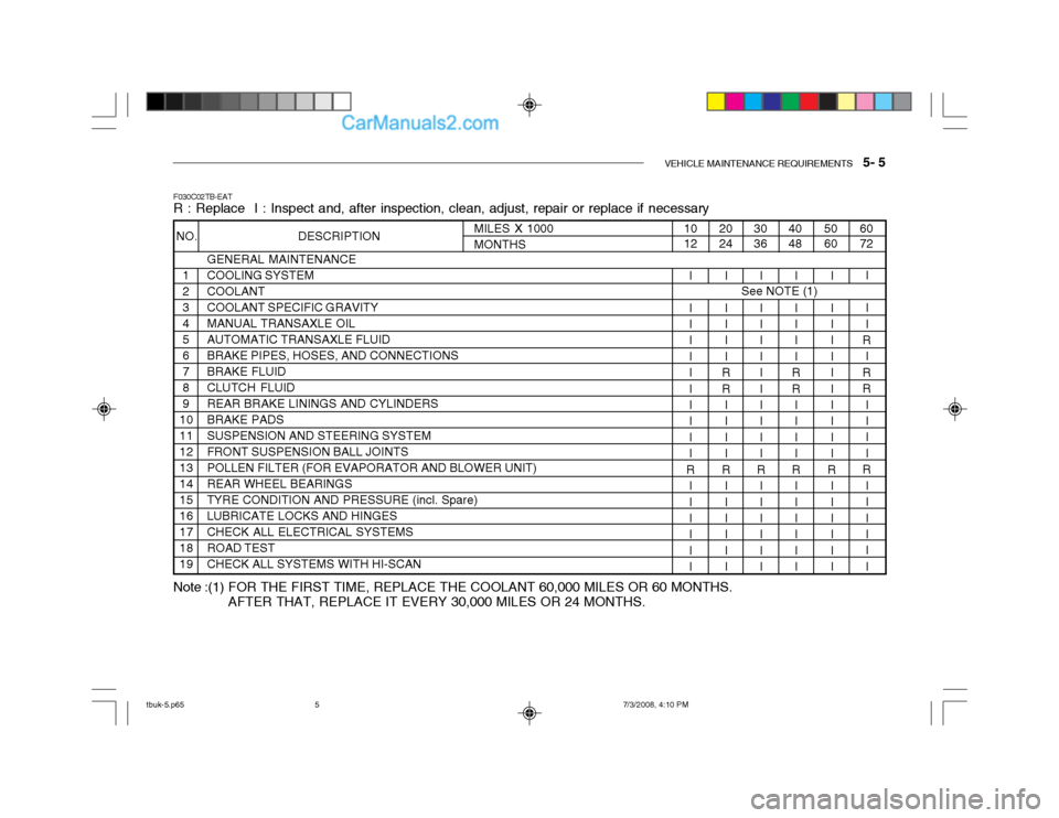
F030C02TB-EAT R : Replace I : Inspect and, after inspection, clean, adjust, repair or replace if necessary
GENERAL MAINTENANCE COOLING SYSTEMCOOLANTCOOLANT SPECIFIC GRAVITYMANUAL TRANSAXLE OILAUTOMATIC TRANSAXLE FLUIDBRAKE PIPES, HOSES, AND CONNECTIONSBRAKE FLUIDCLUTCH FLUIDREAR BRAKE LININGS AND CYLINDERSBRAKE PADSSUSPENSION AND STEERING SYSTEMFRONT SUSPENSION BALL JOINTSPOLLEN FILTER (FOR EVAPORATOR AND BLOWER UNIT)REAR WHEEL BEARINGSTYRE CONDITION AND PRESSURE (incl. Spare)LUBRICATE LOCKS AND HINGESCHECK ALL ELECTRICAL SYSTEMSROAD TESTCHECK ALL SYSTEMS WITH HI-SCAN
60 72
5060
4048
I I I
R
I
RR II I I
R III I II
I I I IIIII I II
R II I III
I I I II
RR I I II
R II I III
30 36
2024
I I I IIIII I II
R II I III
I I I II
RR I I II
R II I III
10 12
I I I IIIII I II
R II I III
MILES X 1000MONTHS
NO. DESCRIPTION
1 23456789
10111213141516171819
See NOTE (1)
Note :(1) FOR THE FIRST TIME, REPLACE THE COOLANT 60,000 MILES OR 60 MONTHS. AFTER THAT, REPLACE IT EVERY 30,000 MILES OR 24 MONTHS.
tbuk-5.p65 7/3/2008, 4:10 PM
5
Page 387 of 445
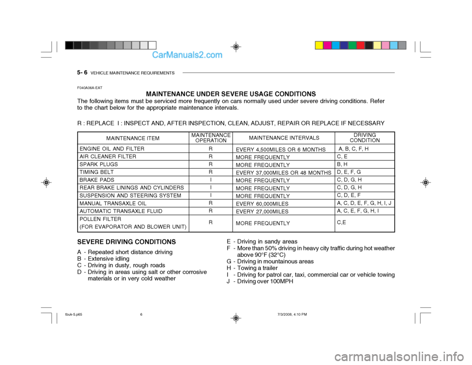
5- 6 VEHICLE MAINTENANCE REQUIREMENTS
MAINTENANCE UNDER SEVERE USAGE CONDITIONS
The following items must be serviced more frequently on cars normally used under severe driving conditions. Refer to the chart below for the appropriate maintenance intervals. R : REPLACE I : INSPECT AND, AFTER INSPECTION, CLEAN, ADJUST, REPAIR OR REPLACE IF NECESSARY
F040A06A-EAT
SEVERE DRIVING CONDITIONS
A - Repeated short distance driving
B - Extensive idling
C - Driving in dusty, rough roads
D - Driving in areas using salt or other corrosive materials or in very cold weather
ENGINE OIL AND FILTER AIR CLEANER FILTERSPARK PLUGSTIMING BELTBRAKE PADSREAR BRAKE LININGS AND CYLINDERSSUSPENSION AND STEERING SYSTEM MANUAL TRANSAXLE OIL AUTOMATIC TRANSAXLE FLUIDPOLLEN FILTER(FOR EVAPORATOR AND BLOWER UNIT)
EVERY 4,500MILES OR 6 MONTHS
MORE FREQUENTLYMORE FREQUENTLY EVERY 37,000MILES OR 48 MONTHSMORE FREQUENTLY MORE FREQUENTLY MORE FREQUENTLYEVERY 60,000MILES EVERY 27,000MILES
MORE FREQUENTLY
MAINTENANCE OPERATIONMAINTENANCE ITEM
R RR RI II
RR R A, B, C, F, H C, EB, H D, E, F, G C, D, G, HC, D, G, HC, D, E, F A, C, D, E, F, G, H, I, J A, C, E, F, G, H, I C,E
MAINTENANCE INTERVALS
DRIVING
CONDITION
E - Driving in sandy areas
F - More than 50% driving in heavy city traffic during hot weather
above 90°F (32°C)
G - Driving in mountainous areas
H - Towing a trailer
I - Driving for patrol car, taxi, commercial car or vehicle towing
J - Driving over 100MPH
tbuk-5.p65 7/3/2008, 4:10 PM
6
Page 389 of 445

5- 8 VEHICLE MAINTENANCE REQUIREMENTS
6ZF070C1-A
o Engine coolant
The coolant should be changed at the intervals specified in the mainte-nance schedule.
6ZF060H1-A
o Air cleaner filter
A Genuine Hyundai air cleaner filter is
recommended when filter is replaced.
6ZF060J1-A
o Spark plugs
Make sure to install new spark plugs
of the correct heat range. 6ZF070B1-A
o Cooling system
Check the cooling system part, such
as radiator, coolant reservoir, hoses and connections for leakage and dam- age. Replace any damaged parts.
6ZF070D1-A
o Manual transaxle oil
Inspect the manual transaxle oil ac-
cording to the maintenance schedule. NOTE:
If the oil level is low, check for
possible leaks before adding oil. Do not overfill.
6ZF060G1-A o Vapour hose and fuel filler cap The vapour hose and fuel filler cap should be inspected at those intervals specified in the maintenance sched- ule. Make sure that a new vapourhose or fuel filler cap is correctly re- placed. 6ZF060F1-A
o Vacuum, crankcase
ventilation hoses
Inspect the surface of hoses for evi- dence of heat and/or mechanical dam-age. Hard and brittle rubber, cracking, tears, cuts, abrasions, and excessive swelling indicate deterioration. Par-ticular attention should be paid to ex- amining those hose surfaces nearest to high heat sources, such as theexhaust manifold.Inspect the hose routing to assurethat the hoses do not come in contact with any heat source, sharp edges or moving component which might causeheat damage or mechanical wear. Inspect all hose connections, such as clamps and couplings, to make surethey are secure, and that no leaks are present. Hoses should be replaced immediately if there is any evidence of deterioration or damage.
F060N01X-GAT
o Valve clearances (1.1 L)
Incorrect valve clearance will not only
result in unsteady engine operation,but will also cause excessive noiseand reduced engine performance. In- spect valve clearance and adjust as required while the engine is hot.
Valve-to-rocker arm clearance Intake valves ..... 0.2 mm (0.008 in.) Exhaust valves ... 0.25 mm (0.010 in.)
tbuk-5.p65 7/3/2008, 4:10 PM
8