check oil Hyundai Getz 2004 Owner's Guide
[x] Cancel search | Manufacturer: HYUNDAI, Model Year: 2004, Model line: Getz, Model: Hyundai Getz 2004Pages: 445, PDF Size: 12.16 MB
Page 217 of 445

6- 30 DO-IT-YOURSELF MAINTENANCE
HTB287
G240A01A-AAT POWER STEERING HOSES It is suggested that you check the power steering hose connections for fluid leakage at regular intervals. Thepower steering hoses should be re- placed if there is severe surface crack- ing, scuffing or worn spots. Deteriora-tion of the hose could cause prema- ture failure. G300A01TB-GAT REMOVAL OF WATER FROM THE FUEL FILTER(DIESEL ENGINE) If the fuel filter warning light illuminates during driving, it indicates that water has accumulated in the fuel filter. If this occurs, remove the water as describedbelow.
G230A03A-GAT POWER STEERING FLUID LEVEL The power steering fluid level should be checked regularly.To check the power steering fluid level, be sure the ignition is "OFF", then check to make certain that the powersteering fluid level is between the "MAX" and "MIN" level markings on the fluid reservoir. NOTE: Grinding noise from the power steering pump may be heard imme-diately after the engine is started in extremely cold conditions (below - 20°C). If the noise stops during warm
HTB163
up, there is no abnormal function in the system. It is due to a power steering fluid characteristic in ex-tremely cold conditions. Recommended Fluid Use PSF-3 type fluid NOTE: Do not start the engine when the power steering oil reservoir is empty.
Page 218 of 445
DO-IT-YOURSELF MAINTENANCE 6- 31
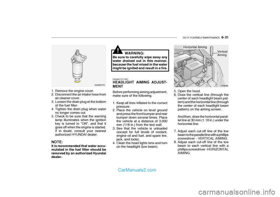
1. Remove the engine cover.
2. Disconnect the air intake hose from
air cleaner cover.
3. Loosen the drain plug at the bottom of the fuel filter.
4. Tighten the drain plug when water no longer comes out.
5. Check to be sure that the warning
lamp illuminates when the ignition key is turned to "ON", and that it goes off when the engine is started. If in doubt, consult your nearestauthorized HYUNDAI dealer.
NOTE: It is recommended that water accu- mulated in the fuel filter should beremoved by an authorized Hyundai dealer. G300B01FC
WARNING:
Be sure to carefully wipe away anywater drained out in this manner, because the fuel mixed in the watermight be ignited and result in a fire.
!
5. Open the hood.
6. Draw the vertical line (through the center of each headlight beam pat-tern) and the horizontal line (throughthe center of each headlight beam pattern) on the aiming screen. And then, draw the horizontal paral- lel line at 30 mm (1.18 in.) under the horizontal line.
7. Adjust each cut-off line of the low beam to the parallel line with a phillipsscrewdriver - VERTICAL AIMING.
8. Adjust each cut-off line of the low
beam to each vertical line with aphillips screwdriver - HORIZONTAL AIMING. HTB269
Horizontal Aiming
Vertical Aiming
G290A01FC-GAT HEADLIGHT AIMING ADJUST- MENT Before performing aiming adjustment, make sure of the following.
1. Keep all tires inflated to the correct pressure.
2. Place the vehicle on level ground
and press the front bumper and rear bumper down several times. Place the vehicle at a distance of 3,000 mm (118 in.) from the test wall.
3. See that the vehicle is unloaded (except for full levels of coolant,engine oil and fuel, and spare tire,jack, and tools).
4. Clean the head lights lens and turn
on the headlight (low beam).
Page 219 of 445
6- 32 DO-IT-YOURSELF MAINTENANCE
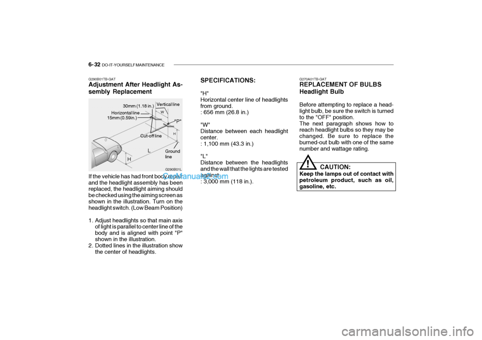
If the vehicle has had front body repair and the headlight assembly has been replaced, the headlight aiming should be checked using the aiming screen asshown in the illustration. Turn on the headlight switch. (Low Beam Position)
1. Adjust headlights so that main axis
of light is parallel to center line of the body and is aligned with point "P"shown in the illustration.
2. Dotted lines in the illustration show
the center of headlights.
G290B01TB-GAT Adjustment After Headlight As- sembly Replacement
SPECIFICATIONS: "H" Horizontal center line of headlightsfrom ground. : 656 mm (26.8 in.) "W" Distance between each headlight center.: 1,100 mm (43.3 in.) "L" Distance between the headlights and the wall that the lights are tested against.: 3,000 mm (118 in.).
G290B01L
LW
H
H Cut-off line
Ground line
"P"
Horizontal line15mm (0.59in.)
30mm (1.18 in.) Vertical line G270A01TB-GAT REPLACEMENT OF BULBS Headlight Bulb Before attempting to replace a head- light bulb, be sure the switch is turned to the "OFF" position.The next paragraph shows how to reach headlight bulbs so they may be changed. Be sure to replace theburned-out bulb with one of the same number and wattage rating.
CAUTION:
Keep the lamps out of contact with petroleum product, such as oil,gasoline, etc.
!
Page 244 of 445

INDEX 10- 3
D Defrosting / Defogging .............................................. 1-80
Door Door locks ................................................................ 1-7
Locking, unlocking front doors with a key ............... 1-7
Drink Holder .............................................................. 1-59
Drive Belts ................................................................ 6-25
Driving
Economical driving ................................................. 2-14
Smooth cornering ................................................... 2-15
Winter driving ......................................................... 2-15
EEmission Control Syst em ........................................... 7-2
Engine Before starting the engine ....................................... 2-3
Compartment ........................................................... 6-2
Coolant ................................................................... 6-13
Coolant temperature gauge ................................... 1-49
If the engine overheats ............................................ 3-4
Number .................................................................... 8-2
Oil ............................................................................. 6-7
Starting ..................................................................... 2-3
Engine Exhaust Can Be Dangerous ........................... 2-2F Fog Light
Front ....................................................................... 1-57
Rear ....................................................................... 1-57
Front Seats Adjustable front seats ............................................ 1-13
Adjustable headrest s .............................................. 1-14
Adjusting seat forward and rear ward..................... 1-13
Adjusting seatback angle .......................................1-13
Lumbar support control .................. ........................ 1-14
Seat cushion height adjustment............................ 1-15
Seat warmer ........................................................... 1-19
Fuel Capacity ................................................................... 9-2
Gauge .................................................................... 1-48
recommendations ..................................................... 1-2
Fuel Filler Lid Remote release ...................................................... 1-68
Fuses ........................................................................ 6-26
Fuse Panel description ............................................. 6-38
G General Checks .......................................................... 6-6
Glove Box ................................................................. 1-63
Page 246 of 445

INDEX 10- 5
P Parking Brake ........................................................... 1-67
Power Steering Fluid Level ............................. ..........6-30
Power Windows ........................................................ 1-12
R Rear Seat .................................................................. 1-15
Rear Window Defroster Switch ................................ 1-56
SSeat Front ....................................................................... 1-13
Seatback Holder ....................................................... 1-70
Seat Pocket .............................................................. 1-70
Seat Warmer ............................................................. 1-19
Seat Belts
3-Point system ....................................................... 1-22
Adjustable height .................................................... 1-22
Adjusting your seat be lt .........................................1-23
Care of seat belts .................................................. 1-21
Precautions ............................................................ 1-20
Spark Plugs ............................................................... 6-15
Spectacle Case ......................................................... 1-63
Speedometer ............................................................. 1-49
Starting ........................................................................ 2-5
Steering Wheel Freeplay .................. ........................ 6-24
Steering Wheel Tilt Lever .............. ...........................1-74
Stereo Radio Operation (K210/K220, K240, H280, HMP280)
................................................. 1-86, 1-91, 1-96, 1-105Stereo Sound System
............................................... 1-84
Sun Visor .................................................................. 1-73
Sunroof ...................................................................... 1-60
T Tachometer ............................................................... 1-49
Tail gate .................................................................... 1-69
Theft-Alarm system ..................................................... 1-9
Tires Balancing .................................................................. 8-5
Chains ...................................................................... 8-4
If you have a flat tire ............................................... 3-6
Information ............................................................... 8-3
Pressure ................................................................... 8-3
Replacement ............................................................ 8-7
Rotation .................................................................... 8-5
Snow tires ................................................................ 8-4
Spare tire ................................................................. 3-5
Traction .................................................................... 8-5
Towing
A trailer (or vehicle) ............................................... 2-18
Emergency ............................................................. 3-13
If your car must be towed .....................................3-11
Trailer or Vehicle towing ........................................... 2-18
Transaxle Automatic ................................................................. 2-9
Automatic transaxle fluid checking ........................6-19
Manual ..................................................................... 2-7
Manual transaxle Oil checking............................... 6-18
Trip Computer ........................................................... 1-51
Trip Odometer ........................................................... 1-50
Page 298 of 445
1- 40 FEATURES OF YOUR HYUNDAI
!
SB210J1-E
HIGH BEAM INDICATOR
LIGHT
The high beam indicator light will illumi-
nate whenever the headlights are
switched to high beam of flash position.
B260H03A-EATPARKING BRAKE/
BRAKE FLUID LEVEL
WARNING LIGHT
SB210K1-E
OIL PRESSURE
WARNING LIGHT
!CAUTION:
If the oil pressure light illuminates
when the engine is running, an in-
sufficient oil pressure level for con-
tinued safe operation of the engine
exists. Continued operation of the
engine in this condition may result
in serious engine damage.
Under normal circumstances, the
light will illuminate when the igni-
tion is turned "on" and will be extin-
guished when the engine is started.
If the oil pressure warning light illu-
minates whilst the engine is run-
ning, stop the engine immediately
and check the engine oil level. If the
level is insufficient, add the required amount of oil as indicated by the
engine oil dipstick. If the light fails to
extinguish when the engine is re-
started, do not continue to operate
the vehicle.
If the oil pressure light illuminates
during normal operation and the
cause is not an insufficient oil level,
or the light fails to illuminate when
the ignition is turned "on", contact
the nearest Hyundai dealer before
further operating the vehicle.
Warning light operation
The parking brake/brake fluid level warn-
ing light will be illuminated whenever
the ignition switch is turned to the "ON"
position irrespective of whether or not
the parking brake is applied and must
be extinguished when the engine starts
and the parking brake released.
If the warning light fails to extinguish or
illuminates at any other time, the ve-
hicle must be brought to rest in a safe
location and the level of brake fluid in
the reservoir checked. If the fluid level
is incorrect, fluid conforming to DOT 3
or DOT 4 specifications should be added.
If, after correcting the brake fluid level,
the warning light continues to be illumi-
nated, the advice of the nearest Hyundai
dealer must be sought before the ve-
hicle is driven again.
Your Hyundai is equipped with a diago-
nally split dual braking system which
will ensure that in the event of one of the
brake circuits becoming defective, ap-
proximately fifty per cent of the normal
braking performance will be available.
If failure of one of the circuits occurs,
the required amount of pedal effort,
pedal travel and stopping distance will
be increased. Use of the gearbox is
WARNING:
In the event of problems being sus-
pected with the braking system, the
advice of the nearest Hyundai dealer
must be sought before the vehicle is
driven. Driving the vehicle with ei-
ther an electrical or hydraulic brak-
ing system defect may be danger-
ous, resulting in accident or per-
sonal injury.
tbuk-1a.p65 3/23/04, 2:22 PM
40
Page 346 of 445
DRIVING YOUR HYUNDAI 2- 3
!
C020A01O-EAT BEFORE STARTING THE EN- GINE Before you start the engine, you should always:
1. Look around the vehicle to be sure
there are no flat tyres, puddles of oil or water or other indications of pos- sible trouble.
2. After entering the car, check to be
sure the parking brake is engaged.
3. Check that all windows, and lights are clean.
4. Check that the interior and exterior
mirrors are clean and in position.
5. Check your seat, seatback and
headrestraint to be sure they are intheir proper positions.
6. Close all the doors.
7. Fasten your seat belt and be sure
that all other occupants have fas- tened theirs.
8. Turn off all lights and accessories that are not needed.
9. When you turn the ignition switch to "ON" check that all appropriate warn-ing lights are operating and that youhave sufficient fuel. 10.Check the operation of warning
lights and all bulbs when key is inthe "ON" position.
WARNING: (DIESEL ENGINE)
To ensure that sufficient vacuum exists within the brake system dur-ing cold weather start-up condi-tions, it is necessary to run theengine at idle for several seconds after starting the engine. SC040A1-F COMBINATION IGNITION SWITCH AND STEERING LOCK To Start the Engine
o If your Hyundai is equipped with a
manual transaxle, place the shift lever in neutral and depress theclutch pedal fully.
o If your Hyundai has an automatic
transaxle, place the shift lever in "P" (park).
o To start the engine, insert the igni-
tion key and turn it to the "START" position. Release it as soon as theengine starts. Do not hold the key inthe "START" position for more that 15 seconds.
NOTE: For safety, the engine will not start if the shift lever is not in "P" or "N"Position (automatic transaxle).
tbuk-2.p65 3/23/04, 4:55 PM
3
Page 360 of 445
DRIVING YOUR HYUNDAI 2- 17
!
o The formation of snow or ice built up
inside the wheel arches may inter- fere with the road wheels or steeringmechanism. In such instances, un-usual noises or an increase in steer- ing effort may result. Therefore, ensure that the wheel arches arechecked periodically and any accu-mulated snow or ice removed.
o It is advisable to carry emergency equipment including, torch, shovel, tow rope, blankets etc., if a journey is to be undertaken into areas ofsevere road conditions.
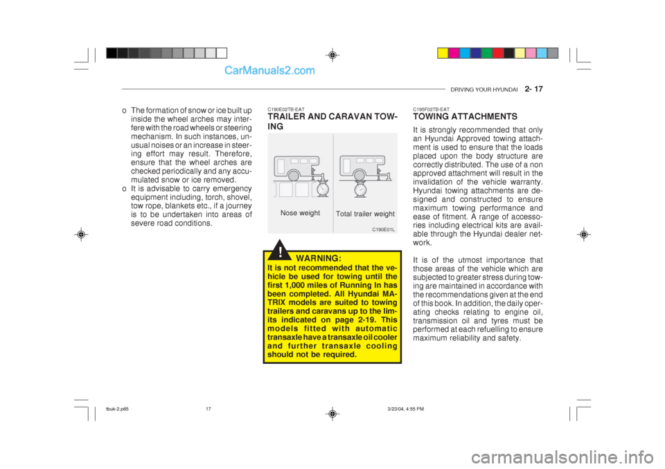
Nose weight Total trailer weight
C190E01L C195F02TB-EAT TOWING ATTACHMENTS It is strongly recommended that only an Hyundai Approved towing attach-ment is used to ensure that the loadsplaced upon the body structure arecorrectly distributed. The use of a non approved attachment will result in the invalidation of the vehicle warranty.Hyundai towing attachments are de-signed and constructed to ensuremaximum towing performance andease of fitment. A range of accesso- ries including electrical kits are avail- able through the Hyundai dealer net-work. It is of the utmost importance that those areas of the vehicle which are subjected to greater stress during tow- ing are maintained in accordance withthe recommendations given at the endof this book. In addition, the daily oper-ating checks relating to engine oil,transmission oil and tyres must be performed at each refuelling to ensure maximum reliability and safety.
C190E02TB-EAT TRAILER AND CARAVAN TOW- ING
WARNING:
It is not recommended that the ve- hicle be used for towing until thefirst 1,000 miles of Running In hasbeen completed. All Hyundai MA- TRIX models are suited to towing trailers and caravans up to the lim-its indicated on page 2-19. Thismodels fitted with automatictransaxle have a transaxle oil coolerand further transaxle cooling should not be required.
tbuk-2.p65 3/23/04, 4:55 PM
17
Page 365 of 445
3- 2 WHAT TO DO IN AN EMERGENCY
HTB165
SD020B1-E
IF THE ENGINE CANNOT BE
CRANKED
1. If the vehicle is fitted with manual
transaxle, ensure that the clutch
pedal is depressed whilst cranking
the engine. If the vehicle is fitted
with automatic transaxle, ensure
that the transaxle selector is at the
"P" or"N" position.
2. Check the battery terminals and
connections to ensure that these
are clean and also tight.
3. If the ignition warning lights dim
when the engine is cranked and the
battery terminals have been
checked, a discharged battery is
indicated. SD020C1-F
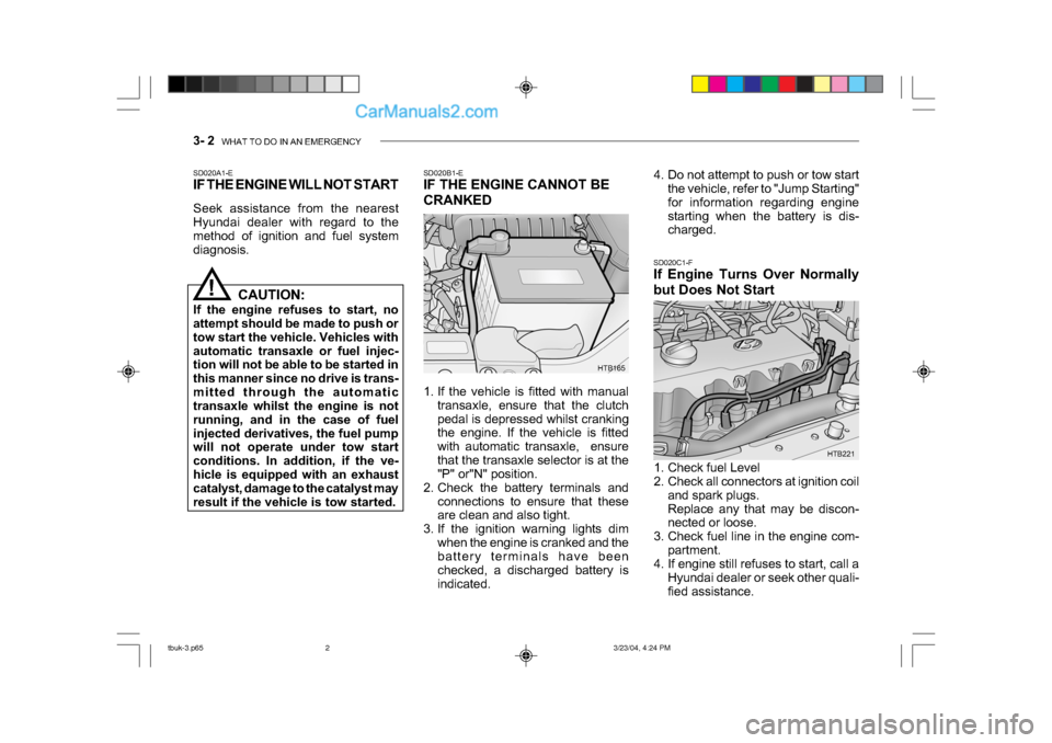
If Engine Turns Over Normally
but Does Not Start
SD020A1-E
IF THE ENGINE WILL NOT START
Seek assistance from the nearest
Hyundai dealer with regard to the
method of ignition and fuel system
diagnosis.
!
HTB221
CAUTION:
If the engine refuses to start, no
attempt should be made to push or
tow start the vehicle. Vehicles with
automatic transaxle or fuel injec-
tion will not be able to be started in
this manner since no drive is trans-
mitted through the automatic
transaxle whilst the engine is not
running, and in the case of fuel
injected derivatives, the fuel pump
will not operate under tow start
conditions. In addition, if the ve-
hicle is equipped with an exhaust
catalyst, damage to the catalyst may
result if the vehicle is tow started. 4. Do not attempt to push or tow start
the vehicle, refer to "Jump Starting"
for information regarding engine
starting when the battery is dis-
charged.
1. Check fuel Level
2. Check all connectors at ignition coil and spark plugs.
Replace any that may be discon-
nected or loose.
3. Check fuel line in the engine com- partment.
4. If engine still refuses to start, call a
Hyundai dealer or seek other quali-
fied assistance.
tbuk-3.p65 3/23/04, 4:24 PM
2
Page 368 of 445
WHAT TO DO IN AN EMERGENCY 3- 5
!
D040A01TB-EAT
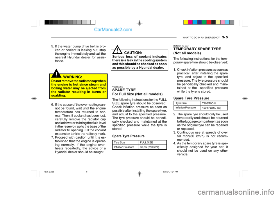
TEMPORARY SPARE TYRE
(Not all models)
The following instructions for the tem-
porary spare tyre should be observed:
1. Check inflation pressure as soon as
practical after installing the spare
tyre, and adjust to the specified
pressure. The tyre pressure should
be periodically checked and main-
tained at the specified pressure
while the tyre is stored.
6. If the cause of the overheating can- not be found, wait until the engine
temperature has returned to nor-
mal. Then, if coolant has been lost,
carefully remove the radiator cap
and add water to bring the fluid level
in the reservoir up to the base of the
radiator fill opening. Fill the coolant
expansion tank to the halfway mark.
7. Proceed with caution until it is es-
tablished that the engine is operat-
ing normally. If the engine over-
heats repeatedly, the advice of a
Hyundai dealer should be sought. WARNING:
Do not remove the radiator cap when
the engine is hot since steam and
boiling water may be ejected from
the radiator resulting in burns or
scalding.
Inflation Pressure
Tyre Size
T105/70D14
420 kPa (60 psi)
2. The spare tyre should only be used temporarily and should be returned
to the luggage compartment as soon
as the original tyre can be repaired
or replaced.
3. Continuous use at speeds of over 50 mph(80 km/h) is not recom-
mended.
4. As the temporary spare tyre is spe- cifically designed for your car, it
should not be used on any other
vehicle.
Spare Tyre Pressure
YD050A1-E
SPARE TYRE
For Full Size (Not all models)
The following instructions for the FULL
SIZE spare tyre should be observed:
Check inflation pressure as soon as
possible after installing the spare tyre,
and adjust to the specified pressure.
The tyre pressure should be periodi-
cally checked and maintained at the
specified pressure while the tyre is
stored.
Spare Tyre Pressure
Tyre Size
Inflation Pressure
FULL SIZE
30 psi (210 kPa)
5. If the water pump drive belt is bro-
ken or coolant is leaking out, stop
the engine immediately and call the
nearest Hyundai dealer for assis-
tance.
! CAUTION:
Serious loss of coolant indicates
there is a leak in the cooling system
and this should be checked as soon
as possible by a Hyundai dealer.
tbuk-3.p65 3/23/04, 4:24 PM
5