lights Hyundai Getz 2004 Workshop Manual
[x] Cancel search | Manufacturer: HYUNDAI, Model Year: 2004, Model line: Getz, Model: Hyundai Getz 2004Pages: 445, PDF Size: 12.16 MB
Page 365 of 445
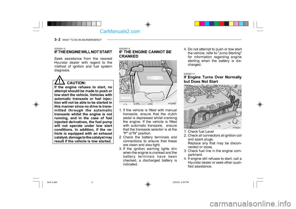
3- 2 WHAT TO DO IN AN EMERGENCY
HTB165
SD020B1-E
IF THE ENGINE CANNOT BE
CRANKED
1. If the vehicle is fitted with manual
transaxle, ensure that the clutch
pedal is depressed whilst cranking
the engine. If the vehicle is fitted
with automatic transaxle, ensure
that the transaxle selector is at the
"P" or"N" position.
2. Check the battery terminals and
connections to ensure that these
are clean and also tight.
3. If the ignition warning lights dim
when the engine is cranked and the
battery terminals have been
checked, a discharged battery is
indicated. SD020C1-F
If Engine Turns Over Normally
but Does Not Start
SD020A1-E
IF THE ENGINE WILL NOT START
Seek assistance from the nearest
Hyundai dealer with regard to the
method of ignition and fuel system
diagnosis.
!
HTB221
CAUTION:
If the engine refuses to start, no
attempt should be made to push or
tow start the vehicle. Vehicles with
automatic transaxle or fuel injec-
tion will not be able to be started in
this manner since no drive is trans-
mitted through the automatic
transaxle whilst the engine is not
running, and in the case of fuel
injected derivatives, the fuel pump
will not operate under tow start
conditions. In addition, if the ve-
hicle is equipped with an exhaust
catalyst, damage to the catalyst may
result if the vehicle is tow started. 4. Do not attempt to push or tow start
the vehicle, refer to "Jump Starting"
for information regarding engine
starting when the battery is dis-
charged.
1. Check fuel Level
2. Check all connectors at ignition coil and spark plugs.
Replace any that may be discon-
nected or loose.
3. Check fuel line in the engine com- partment.
4. If engine still refuses to start, call a
Hyundai dealer or seek other quali-
fied assistance.
tbuk-3.p65 3/23/04, 4:24 PM
2
Page 366 of 445
WHAT TO DO IN AN EMERGENCY 3- 3
!
HTB218
Discharged
battery
Booster
battery
CAUTION:
Personal injury and damage to the
vehicle may occur if jump starting
is not performed correctly. If any
doubt exists as to how this opera-
tion should be performed, seek as-
sistance from qualified personnel.
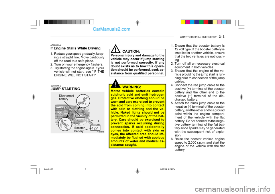
SD030A1-E
JUMP STARTING
AD020D1-A
If Engine Stalls While Driving
1. Reduce your speed gradually, keep-
ing a straight line. Move cautiously
off the road to a safe place.
2. Turn on your emergency flashers.
3. Try starting the engine again. If your
vehicle will not start, see "IF THE
ENGINE WILL NOT START"!
WARNING:
Motor vehicle batteries contain
sulphuric acid and emit hydrogen
gas. Protective clothing should be
worn and care exercised to prevent
the acid from coming into contact
with skin or clothing and the ve-
hicle. Naked lights should not be
permitted in the vicinity of the bat-
tery. Care should be exercised to
prevent sparks occurring during
connection. If acid accidentally
comes into contact with skin or
eyes, the affected area should im-
mediately be flushed with copious
amounts of water and medical as-
sistance sought. 1. Ensure that the booster battery is
12 volt type. If the booster battery is
installed in another vehicle, ensure
that the two vehicles are not touch-
ing.
2. Turn off all unnecessary electrical equipment in both vehicles.
3. Ensure that the engine of the ve-
hicle providing the jump start is run-
ning prior to connection of the jump
cables.
4. Connect the red jump cable to the positive (+) terminal of the booster
battery and the other end to the
positive (+) terminal of the dis-
charged battery.
5. Attach the black jump cable to the
negative (-) terminal of the booster
battery, and the other end to a ground
point within the engine compart-
ment of the vehicle with the flat
battery. Do not connect to the nega-
tive battery terminal of the flat bat-
tery since sparks may be generated
with the subsequent risk of explo-
sion.
6. Raise the booster vehicle engine speed to 2,000 r.p.m. and start the
engine of the vehicle with the flat
battery.
tbuk-3.p65 3/23/04, 4:24 PM
3
Page 416 of 445
DO-IT-YOURSELF MAINTENANCE 6- 25
!
!
o If battery electrolyte is spilled onto
skin or into eyes, the effected area
must be flushed with copious
amounts of water and medical assis-
tance sought.
o If battery electrolyte is ingested, copious amounts of water or milk
followed by an ant-acid (raw egg or
milk of magnesia) must be drunk.
Vomiting should not be induced and
medical assistance must be sought.
o Batteries must only be charged in well venti-lated areas from which
naked lights or sources of sparks are
excluded.
o Ensure that children, pets or other unauthorized persons are kept away
from batteries.
o Do not allow anything to bridge the positive (+) and negative (-) termi-
nals of the battery.
o Never invert the battery.
The battery fitted during production is of
the "Maintenance Free" type.
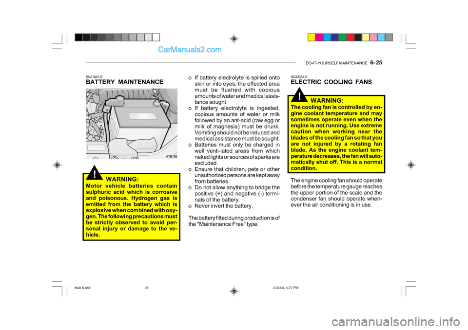
SG210A1-E
BATTERY MAINTENANCE
WARNING:
Motor vehicle batteries contain
sulphuric acid which is corrosive
and poisonous. Hydrogen gas is
emitted from the battery which is
explosive when combined with oxy-
gen. The following precautions must
be strictly observed to avoid per-
sonal injury or damage to the ve-
hicle.
HTB165 SG220A1-E
ELECTRIC COOLING FANS
WARNING:
The cooling fan is controlled by en-
gine coolant temperature and may
sometimes operate even when the
engine is not running. Use extreme
caution when working near the
blades of the cooling fan so that you
are not injured by a rotating fan
blade. As the engine coolant tem-
perature decreases, the fan will auto-
matically shut off. This is a normal
condition.
The engine cooling fan should operate
before the temperature gauge reaches
the upper portion of the scale and the
condenser fan should operate when-
ever the air conditioning is in use.
tbuk-6.p65 3/23/04, 4:27 PM
25
Page 418 of 445
DO-IT-YOURSELF MAINTENANCE 6- 27
!
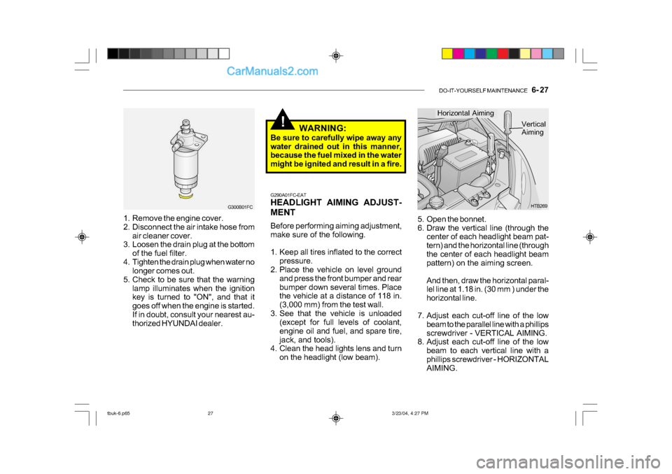
5. Open the bonnet.
6. Draw the vertical line (through the
center of each headlight beam pat-
tern) and the horizontal line (through
the center of each headlight beam
pattern) on the aiming screen.
And then, draw the horizontal paral-
lel line at 1.18 in. (30 mm ) under the
horizontal line.
7. Adjust each cut-off line of the low beam to the parallel line with a phillips
screwdriver - VERTICAL AIMING.
8. Adjust each cut-off line of the low
beam to each vertical line with a
phillips screwdriver - HORIZONTAL
AIMING. HTB269
Horizontal Aiming
Vertical
Aiming
G290A01FC-EAT
HEADLIGHT AIMING ADJUST-
MENT
Before performing aiming adjustment,
make sure of the following.
1. Keep all tires inflated to the correct pressure.
2. Place the vehicle on level ground
and press the front bumper and rear
bumper down several times. Place
the vehicle at a distance of 118 in.
(3,000 mm) from the test wall.
3. See that the vehicle is unloaded (except for full levels of coolant,
engine oil and fuel, and spare tire,
jack, and tools).
4. Clean the head lights lens and turn
on the headlight (low beam). WARNING:
Be sure to carefully wipe away any
water drained out in this manner,
because the fuel mixed in the water
might be ignited and result in a fire.
1. Remove the engine cover.
2. Disconnect the air intake hose from air cleaner cover.
3. Loosen the drain plug at the bottom
of the fuel filter.
4. Tighten the drain plug when water no longer comes out.
5. Check to be sure that the warning lamp illuminates when the ignition
key is turned to "ON", and that it
goes off when the engine is started.
If in doubt, consult your nearest au-
thorized HYUNDAI dealer.
G300B01FC
tbuk-6.p65 3/23/04, 4:27 PM
27
Page 419 of 445
6- 28 DO-IT-YOURSELF MAINTENANCE
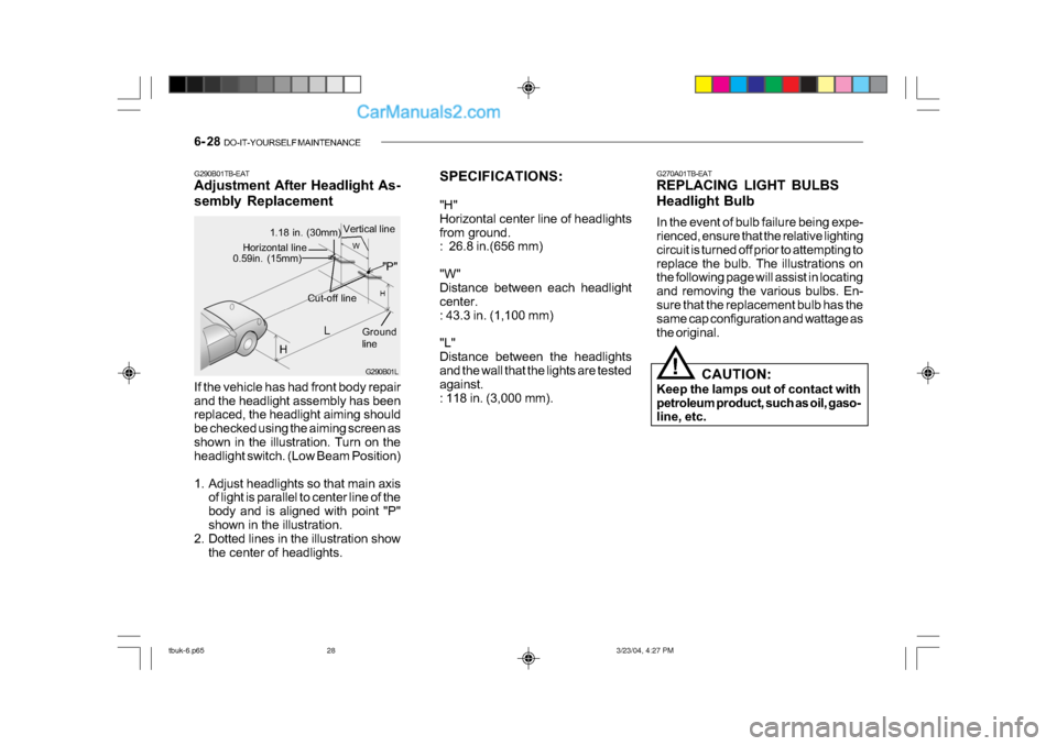
SPECIFICATIONS:
"H"
Horizontal center line of headlights
from ground.
: 26.8 in.(656 mm)
"W"
Distance between each headlight
center.
: 43.3 in. (1,100 mm)
"L"
Distance between the headlights
and the wall that the lights are tested
against.
: 118 in. (3,000 mm). G270A01TB-EAT
REPLACING LIGHT BULBS
Headlight Bulb
In the event of bulb failure being expe-
rienced, ensure that the relative lighting
circuit is turned off prior to attempting to
replace the bulb. The illustrations on
the following page will assist in locating
and removing the various bulbs. En-
sure that the replacement bulb has the
same cap configuration and wattage as
the original.
!
CAUTION:
Keep the lamps out of contact with
petroleum product, such as oil, gaso-
line, etc.
If the vehicle has had front body repair
and the headlight assembly has been
replaced, the headlight aiming should
be checked using the aiming screen as
shown in the illustration. Turn on the
headlight switch. (Low Beam Position)
1. Adjust headlights so that main axis
of light is parallel to center line of the
body and is aligned with point "P"
shown in the illustration.
2. Dotted lines in the illustration show
the center of headlights.
G290B01TB-EAT
Adjustment After Headlight As-
sembly ReplacementG290B01L
L
W
H
H Cut-off line
Ground
line
"P"
Horizontal line0.59in. (15mm)
1.18 in. (30mm) Vertical line
tbuk-6.p65
3/23/04, 4:27 PM
28