fuel cap Hyundai Getz 2004 Owner's Manual
[x] Cancel search | Manufacturer: HYUNDAI, Model Year: 2004, Model line: Getz, Model: Hyundai Getz 2004Pages: 445, PDF Size: 12.16 MB
Page 61 of 445
1- 48 FEATURES OF YOUR HYUNDAI
B270A01A-AAT BRAKE PAD WEAR WARNING SOUND The front disc brake pads have wear indicators that should make a high- pitched squealing or scraping noisewhen new pads are needed. The sound may come and go or be heard all the time when the vehicle is moving. Itmay also be heard when the brake pedal is pushed down firmly. Exces- sive rotor damage will result if the wornpads are not replaced. See your Hyundai dealer immediately.
B900A01A-GAT ACOUSTIC WARNING SOUND (If Installed) The acoustic warning chime sounds when the tail lights are on and the doorin driver side is open. This prevents the battery from discharging when the car is left with the tail lights on. The chimesounds until the tail lights are turned off. HTB006
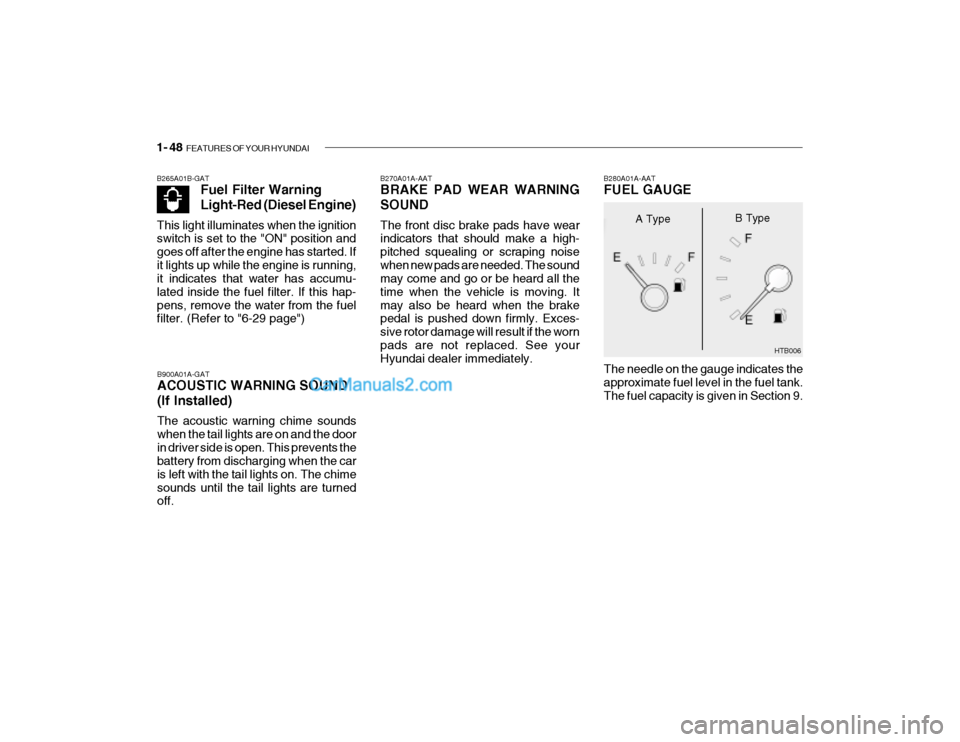
The needle on the gauge indicates theapproximate fuel level in the fuel tank. The fuel capacity is given in Section 9.
B280A01A-AAT FUEL GAUGE
A Type
B Type
B265A01B-GAT
Fuel Filter Warning Light-Red (Diesel Engine)
This light illuminates when the ignition switch is set to the "ON" position and goes off after the engine has started. Ifit lights up while the engine is running, it indicates that water has accumu- lated inside the fuel filter. If this hap-pens, remove the water from the fuel filter. (Refer to "6-29 page")
Page 82 of 445
FEATURES OF YOUR HYUNDAI 1- 69
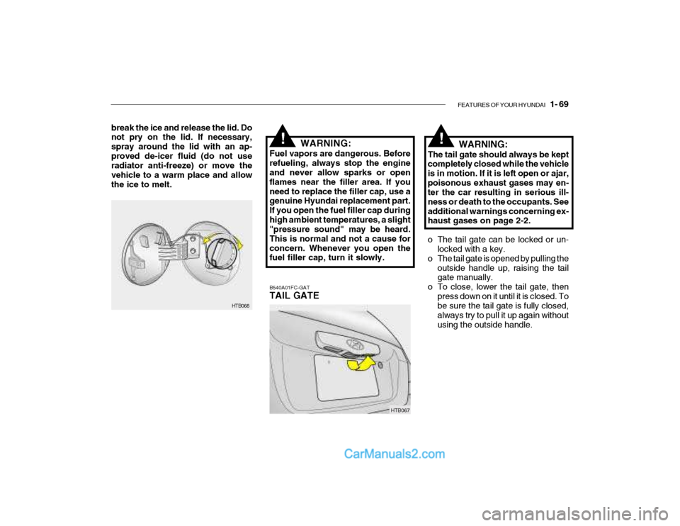
break the ice and release the lid. Do not pry on the lid. If necessary, spray around the lid with an ap-proved de-icer fluid (do not use radiator anti-freeze) or move the vehicle to a warm place and allowthe ice to melt.
B540A01FC-GAT TAIL GATE
HTB067WARNING:
The tail gate should always be kept completely closed while the vehicle is in motion. If it is left open or ajar,poisonous exhaust gases may en- ter the car resulting in serious ill- ness or death to the occupants. Seeadditional warnings concerning ex- haust gases on page 2-2.
o The tail gate can be locked or un- locked with a key.
o The tail gate is opened by pulling the outside handle up, raising the tail gate manually.
o To close, lower the tail gate, then press down on it until it is closed. Tobe sure the tail gate is fully closed, always try to pull it up again withoutusing the outside handle.
HTB068
!!WARNING:
Fuel vapors are dangerous. Before refueling, always stop the engine and never allow sparks or open flames near the filler area. If youneed to replace the filler cap, use a genuine Hyundai replacement part. If you open the fuel filler cap duringhigh ambient temperatures, a slight "pressure sound" may be heard. This is normal and not a cause forconcern. Whenever you open the
fuel filler cap, turn it slowly.
Page 180 of 445
5- 4 VEHICLE MAINTENANCE REQUIREMENTS
ENGINE CONTROL SYSTEM MAINTENANCE (GASOLINE)
1 ENGINE OIL & FILTER (SG OR ABOVE) See Note (1)
2 DRIVE BELT (WATER PUMP, ALTERNATOR & A/CON)
3 FUEL FILTER (MPI)
4 FUEL LINES, FUEL HOSES & CONNECTIONS
5 TIMING BELT
6 VAPOR HOSE & FUEL FILLER CAP
7 VACUUM CRANKCASE VENTILATION HOSES
8 AIR CLEANER FILTER
9 SPARK PLUGS
10 VALVE CLEARANCE (1.1 L)
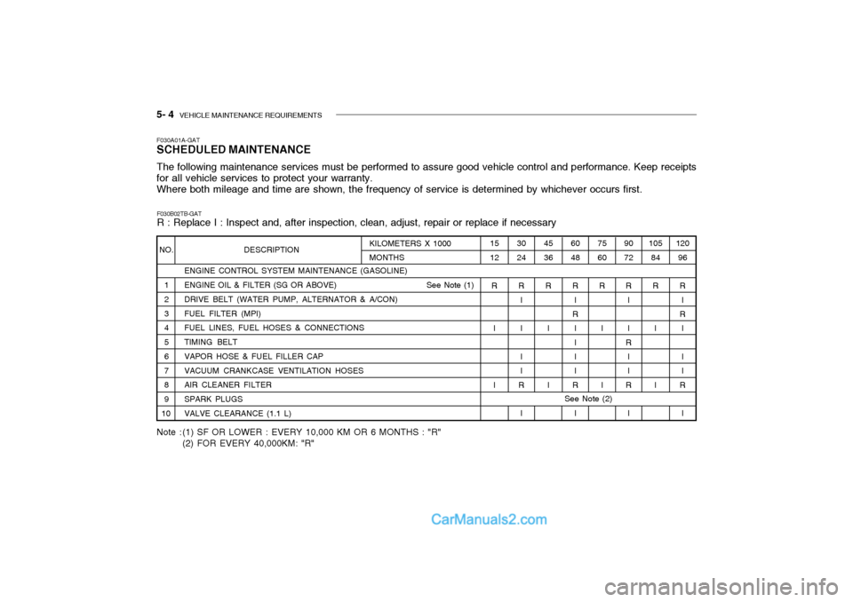
F030A01A-GAT SCHEDULED MAINTENANCE The following maintenance services must be performed to assure good vehicle control and performance. Keep receipts for all vehicle services to protect your warranty.Where both mileage and time are shown, the frequency of service is determined by whichever occurs first.
NO. DESCRIPTION105
84
R
I I 120
96
R I
R
I I I
R
I
9072
R I I
R I I
R
I
7560
R
I I
60 48
R I
R
II I I
R
I
4536
R
I I
30 24
R I II I
R
I
1512
R
I I
KILOMETERS X 1000 MONTHS
F030B02TB-GAT R : Replace I : Inspect and, after inspection, clean, adjust, repair or replace if necessary
Note : (1) SF OR LOWER : EVERY 10,000 KM OR 6 MONTHS : "R" (2) FOR EVERY 40,000KM: "R"
See Note (2)
Page 184 of 445
5- 8 VEHICLE MAINTENANCE REQUIREMENTS
F060A01A-AAT EXPLANATION OF SCHEDULED MAINTENANCE ITEMS F060M01A-AAT
o Engine Oil and Filter The engine oil and filter should be changed at the intervals specified in the maintenance schedule. If the car is being driven in severe conditions,more frequent oil and filter changes are required. F060B01A-AAT
o Drive Belts Inspect all drive belts for evidence of cuts, cracks, excessive wear or oil and replace if necessary. Drive beltsshould be checked periodically for proper tension and adjusted as nec- essary. placement more frequently.
After installing a new filter, run the
engine for several minutes, and check for leaks at the connections. Fuel fil- ters should be installed by trainedtechnicians.
F060D01TB-AAT
o Fuel Lines, Fuel Hoses and
Connections
Check the fuel lines, fuel hoses and
connections for leakage and damage.Have a trained technician replace anydamaged or leaking parts immedi- ately. F060E01A-AAT
o Timing Belt
Inspect all parts related to the timingbelt for damage and deformation. Replace any damaged parts immedi-ately. F060G01A-AAT
o Vapor Hose and Fuel Filler Cap
The vapor hose and fuel filler cap should be inspected at those intervals specified in the maintenance sched-ule. Make sure that a new vapor hose or fuel filler cap is correctly replaced.
F060C01A-AAT
o Fuel Filter A clogged filter can limit the speed at which the vehicle may be driven, dam- age the emission system and cause hard starting. If an excessive amountof foreign matter accumulates in the fuel tank, the filter may require re-
!WARNING (Diesel only):
Never work on injection system with
engine running or within 30 sec- onds after shutting off engine. High pressure pump, rail, injectors and high pressure pipes are subjectedto high pressure even after the en- gine has been switched off. The fuel jet produced by fuel leaks maycause serious injury, if it contacts with the body. People using pace- makers should not move closerthan 30cm to the ECU or wiring harness within the engine room with the engine running, since the high currents in the Common Railsystem produce considerable mag- netic fields.
Page 189 of 445
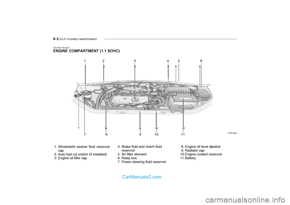
6- 2 DO-IT-YOURSELF MAINTENANCE
HTB160A
1. Windshield washer fluid reservoir cap
2. Auto fuel cut switch (If installed)
3. Engine oil filler cap 4. Brake fluid and clutch fluid
reservoir
5. Air filter element
6. Relay box
7. Power steering fluid reservoir 8. Engine oil level dipstick
9. Radiator cap
10.Engine coolant reservoir
11.Battery
G010A01TB-GAT ENGINE COMPARTMENT (1.1 SOHC)
12 3
456
78 9 10 1 1
Page 190 of 445
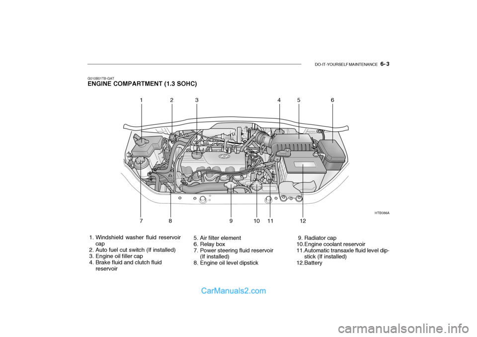
DO-IT-YOURSELF MAINTENANCE 6- 3
G010B01TB-GAT ENGINE COMPARTMENT (1.3 SOHC)
1. Windshield washer fluid reservoir
cap
2. Auto fuel cut switch (If installed)
3. Engine oil filler cap
4. Brake fluid and clutch fluid reservoir 5. Air filter element
6. Relay box
7. Power steering fluid reservoir
(If installed)
8. Engine oil level dipstick 9. Radiator cap
10.Engine coolant reservoir
11.Automatic transaxle fluid level dip-
stick (If installed)
12.Battery HTB086A
123
456
78 91 011
12
Page 191 of 445
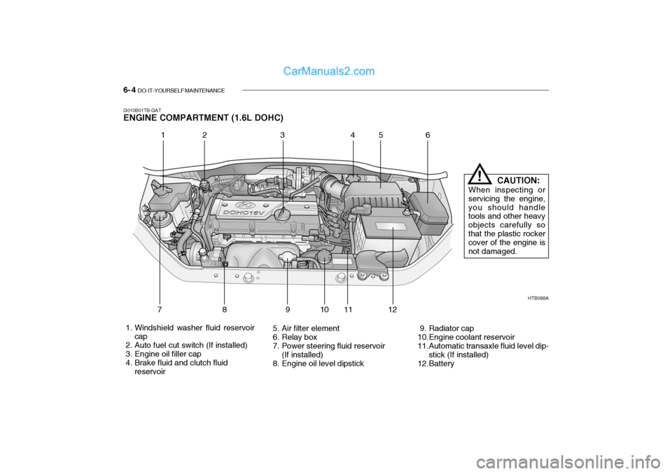
6- 4 DO-IT-YOURSELF MAINTENANCE
G010B01TB-GAT ENGINE COMPARTMENT (1.6L DOHC)
HTB088A
1. Windshield washer fluid reservoir cap
2. Auto fuel cut switch (If installed)
3. Engine oil filler cap
4. Brake fluid and clutch fluid reservoir 5. Air filter element
6. Relay box
7. Power steering fluid reservoir
(If installed)
8. Engine oil level dipstick 9. Radiator cap
10.Engine coolant reservoir
11.Automatic transaxle fluid level dip-
stick (If installed)
12.Battery
1 2 34
56
789 10 11 12 CAUTION:
When inspecting or servicing the engine,you should handle tools and other heavy objects carefully sothat the plastic rocker cover of the engine is not damaged.
!
Page 192 of 445
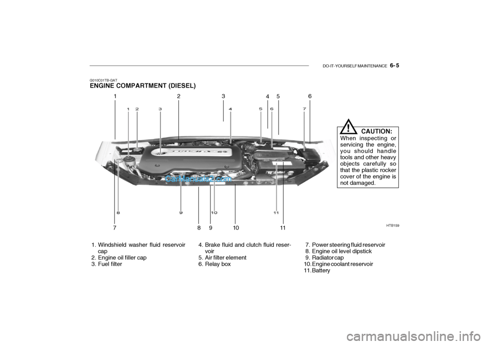
DO-IT-YOURSELF MAINTENANCE 6- 5
G010C01TB-GAT ENGINE COMPARTMENT (DIESEL)
HTB159
1. Windshield washer fluid reservoir cap
2. Engine oil filler cap
3. Fuel filter 4. Brake fluid and clutch fluid reser-
voir
5. Air filter element
6. Relay box 7. Power steering fluid reservoir
8. Engine oil level dipstick
9. Radiator cap
10. Engine coolant reservoir
11. Battery
12
3
45 6
78 910
11 CAUTION:
When inspecting or servicing the engine,you should handle tools and other heavy objects carefully sothat the plastic rocker cover of the engine is not damaged.
!
Page 202 of 445

DO-IT-YOURSELF MAINTENANCE 6- 15
HTB172
5. Start the engine, top off the radiator with water and then add engine coolant to the reservoir until the level is between "LOW" and "FULL".
6. Replace the radiator and reservoir caps and check to be sure the draincocks are fully closed and not leak-ing.
WARNING:
The cooling fan is controlled byengine coolant temperature and may sometimes operate even when the engine is not running. Use ex-treme caution when working near the blades of the cooling fan so that you are not injured by a rotating fan blade. As the engine coolant tem-perature decreases, the fan will au- tomatically shut off. This is a nor- mal condition.
!
G060B02S-GAT REPLACING THE SPARK PLUGS
CHAMPION NGK
RC10YC BKR5ES
Unleaded
engine Leaded
engine
RC10YC4 BKR5ES-11
G060A01L
Unleaded: 1.0 ~ 1.1 mm (0.039 ~ 0.043 in.) Leaded: 0.7 ~ 0.8 mm(0.028 ~ 0.032 in.)
The spark plugs should be changed at the intervals specified in the vehicle maintenances schedule in Section 5 or whenever engine performance indi-cates they should be changed. Symp- toms that suggest poor spark plug performance include engine misfiringunder load, loss of fuel economy, poor acceleration, etc. When spark plugs are replaced, always use spark plugs recommended by Hyundai. The use ofother spark plugs can result in loss of performance, radio interference or engine damage. NOTE: When replacing the spark plugs, always use genuine parts recom-mended. Recommended Spark Plugs:
Page 229 of 445
7- 2 EMISSION CONTROL SYSTEMS
H010A01A-GAT
EMISSION CONTROL SYSTEM (If Installed)
Your Hyundai is equipped with an
emission control system to meet all requirements of the Emission prohibi- tion rules of your province.
There are three emission control sys-
tems which are as follows.
1) Crankcase emission control sys-
tem
2) Evaporative emission control sys- tem
3) Exhaust emission control system
In order to assure the proper function
of the emission control systems, it is recommended that you have your carinspected and maintained by an au- thorized Hyundai dealer in accordance with the maintenance schedule in thismanual. H010B01A-AAT
1. Crankcase Emission Control
System
The positive crankcase ventilation
system is employed to prevent airpollution caused by blow-by gases being emitted from the crankcase. This system supplies fresh air to thecrankcase through the air intake hose. Inside the crankcase, the fresh air mixes with blow-by gases, which thenpass through the PCV valve and into the induction system.
H010C01E-GAT
2. Evaporative Emission Con- trol System
The Evaporative Emission Control
System is designed to prevent fuel vapors from escaping into the atmo-sphere. Canister
While the engine is inoperative, fuel
vapors generated inside the fuel tank are absorbed and stored in the canis- ter. When the engine is running, the fuel vapors absorbed in the canister are drawn into the induction system through
the purge control solenoid valve.
Purge Control Solenoid Valve (PCSV) The purge control solenoid valve is
controlled by the Engine Control Mod- ule (ECM); when the engine coolanttemperature is low during idling, the PCSV closes so that evaporated fuel is not taken into the engine. After theengine warms-up during ordinary driv- ing, the PCSV opens so as to intro- duce evaporated fuel to the engine. H010D01A-AAT
3. Exhaust Emission Control
System
The exhaust emission control system is a highly effective system whichcontrols exhaust emission while main- taining good vehicle performance.