low beam Hyundai Getz 2009 Owner's Manual - RHD (UK, Australia)
[x] Cancel search | Manufacturer: HYUNDAI, Model Year: 2009, Model line: Getz, Model: Hyundai Getz 2009Pages: 191, PDF Size: 6.3 MB
Page 10 of 191

YOUR VEHICLE AT A GLANCE
F10
G255A01TB-DAT INDICATOR SYMBOLS ON THE INSTRUMENT PANEL * A detailed explanation of these items will be found on page 1-37
SRS (Airbag) Service Reminder Indicator ABS Service Reminder Indicator Turn Signal Indicator Lights High Beam Indicator Light Oil Pressure Warning Light Hand Brake/Brake Fluid Level Warning Light Charging System Warning LightTail Gate Open Warning Light
Door Ajar Warning Light and Chime
Low Fuel Level Warning Light Malfunction Indicator Light Seat Belt Reminder Light
O/D OFF Indicator (Automatic transaxle only)
Immobiliser Indicator Light
Electronic Stability Program Indicator Lights (If Installed)
Engine Coolant Temperature Indicator
Page 46 of 191
FEATURES OF YOUR HYUNDAI 1- 35
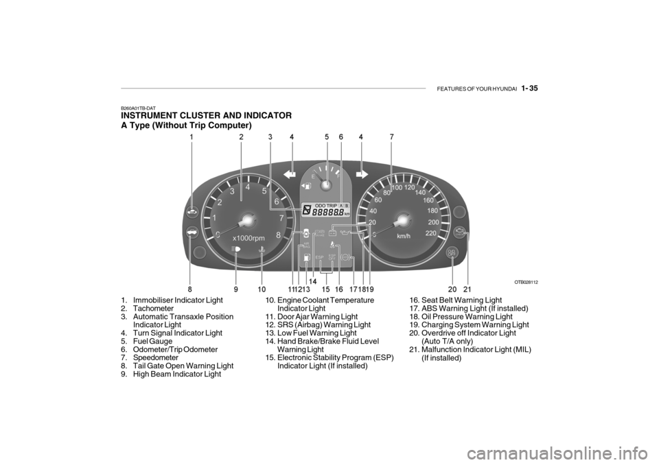
B260A01TB-DAT INSTRUMENT CLUSTER AND INDICATOR A Type (Without Trip Computer)
1. Immobiliser Indicator Light
2. Tachometer
3. Automatic Transaxle Position Indicator Light
4. Turn Signal Indicator Light
5. Fuel Gauge
6. Odometer/Trip Odometer
7. Speedometer
8. Tail Gate Open Warning Light
9. High Beam Indicator Light OTB028112
10. Engine Coolant Temperature Indicator Light
11. Door Ajar Warning Light
12. SRS (Airbag) Warning Light
13. Low Fuel Warning Light
14. Hand Brake/Brake Fluid Level Warning Light
15. Electronic Stability Program (ESP)
Indicator Light (If installed) 16. Seat Belt Warning Light
17. ABS Warning Light (If installed)
18. Oil Pressure Warning Light
19. Charging System Warning Light
20. Overdrive off Indicator Light
(Auto T/A only)
21. Malfunction Indicator Light (MIL)
(If installed)
Page 47 of 191
1- 36 FEATURES OF YOUR HYUNDAI
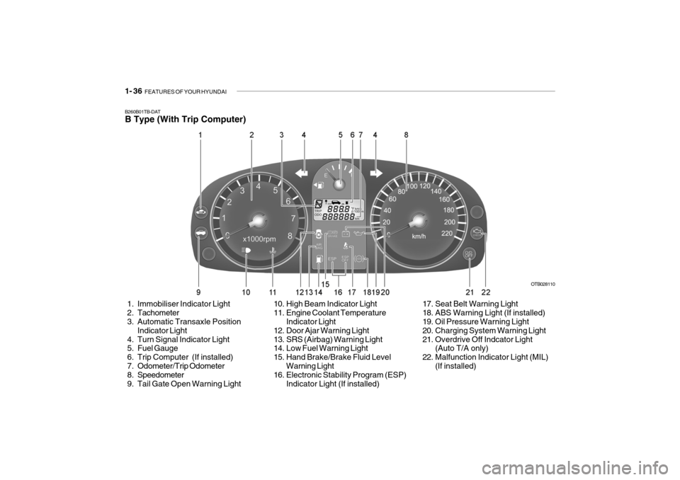
B260B01TB-DAT B Type (With Trip Computer)
1. Immobiliser Indicator Light
2. Tachometer
3. Automatic Transaxle Position
Indicator Light
4. Turn Signal Indicator Light
5. Fuel Gauge
6. Trip Computer (If installed)
7. Odometer/Trip Odometer
8. Speedometer
9. Tail Gate Open Warning Light OTB028110
10. High Beam Indicator Light
11. Engine Coolant Temperature Indicator Light
12. Door Ajar Warning Light
13. SRS (Airbag) Warning Light
14. Low Fuel Warning Light
15. Hand Brake/Brake Fluid Level
Warning Light
16. Electronic Stability Program (ESP)
Indicator Light (If installed) 17. Seat Belt Warning Light
18. ABS Warning Light (If installed)
19. Oil Pressure Warning Light
20. Charging System Warning Light
21. Overdrive Off Indcator Light
(Auto T/A only)
22. Malfunction Indicator Light (MIL)
(If installed)
Page 58 of 191
FEATURES OF YOUR HYUNDAI 1- 47
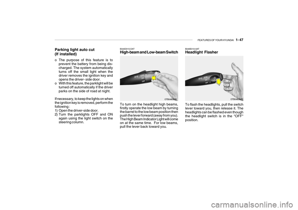
B340D01S-DAT High-beam and Low-beam Switch
Parking light auto cut (If installed)
o The purpose of this feature is to
prevent the battery from being dis- charged. The system automaticallyturns off the small light when the driver removes the ignition key and opens the driver- side door.
o With this feature, the parklight will be turned off automatically if the driverparks on the side of road at night.
If necessary, to keep the lights on whenthe ignition key is removed, perform thefollowing :
1) Open the driver-side door.
2) Turn the parklights OFF and ON again using the light switch on the steering column. To turn on the headlight high beams, firstly operate the low beam by turning the barrel to the low beam position then push the lever forward (away from you). The High Beam Indicator Light will come on at the same time. For low beams, pull the lever back toward you.
OTB048093ROTB048094R
B340E01A-AAT Headlight Flasher To flash the headlights, pull the switch lever toward you, then release it. The headlights can be flashed even thoughthe headlight switch is in the "OFF" position.
Page 113 of 191
2- 18 DRIVING YOUR HYUNDAI
!
C190C02S-DAT Trailer Brakes If your trailer is equipped with a braking system, make sure it conforms to fed-eral and/or local regulations and that it is properly installed and operating cor- rectly. NOTE: If you tow a trailer or vehicle, your car will require more frequent main- tenance due to the additional load.See "Maintenance Under Severe Usage Conditions" on page 5-4.
!
C190B01FC-DAT Trailer Tow Bars Select the proper tow bar and ball combination, making sure that its loca-tion is compatible with that of the trailer or vehicle being towed. We recom- mend only genuine Hyundai tow bars(the tow bars are made and tested in Australia for local conditions). Use a quality non-equalising hitch which dis-tributes the tongue load uniformly throughout the chassis. Maintain 4% of the trailer load on thetrailer tongue for dead weight hitches. Tongue loads can be increased or decreased by redistributing the load inthe trailer. This can be verified by checking the total weight of the loaded trailer and then checking the load onthe tongue.
WARNING:
Improperly loading your car andtrailer can serious affect its steer-ing and braking performance caus- ing a crash in which you may be seriously injured. CAUTION:
o Never connect a trailer brake sys- tem directly to the vehicle brake system.
o When towing a trailer on steep grades (in excess of 6%) pay closeattention to the engine coolant temperature gauge to ensure theengine does not overheat.
C180A01A-AAT USE OF LIGHTS Check your lights regularly for correct operation and always keep them clean.When driving during the day in condi- tions of poor visibility, it is helpful to drive with headlights on low beam.This enables you to be seen as well as to see. C190A01A-DAT TRAILER OR VEHICLE TOWING If you are considering towing with your car, you should first check with your State Department of Motor Vehicles to determine their legal requirements.Since laws vary from state to state the requirements for towing trailers, cars, or other types of vehicles or apparatusmay differ. Ask your Hyundai dealer for further details before towing.
!
CAUTION
Do not do any towing with your car during its first 2,000 km (1,200 miles) in order to allow the engine to prop- erly break in. Failure to heed thiscaution may result in serious en- gine or transaxle damage.
Page 165 of 191
DO-IT-YOURSELF MAINTENANCE 6- 23
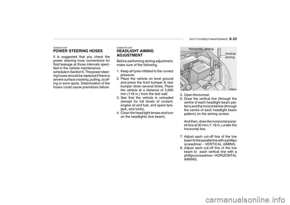
G290A01FC-DAT HEADLIGHT AIMING ADJUSTMENT Before performing aiming adjustment, make sure of the following.
1. Keep all tyres inflated to the correct
pressure.
2. Place the vehicle on level ground
and press the front bumper & rear bumper down several times. Place the vehicle at a distance of 3,000 mm (118 in.) from the test wall.
3. See that the vehicle is unloaded (except for full levels of coolant,engine oil and fuel, and spare tyre,jack, and tools).
4. Clean the head light lenses and turn
on the headlights (low beam).
G240A01A-DAT POWER STEERING HOSES It is suggested that you check the power steering hose connections forfluid leakage at those intervals speci- fied in the vehicle maintenance schedule in Section 5. The power steer-ing hoses should be replaced if there is severe surface cracking, pulling, scuff- ing or worn spots. Deterioration of thehoses could cause premature failure.
HTB269
Horizontal aiming
Vertical
aiming
5. Open the bonnet.
6. Draw the vertical line (through the centre of each headlight beam pat-tern) and the horizontal line (throughthe centre of each headlight beam pattern) on the aiming screen. And then, draw the horizontal paral- lel line at 30 mm (1.18 in.) under the horizontal line.
7. Adjust each cut-off line of the low beam to the parallel line with a phillipsscrewdriver - VERTICAL AIMING.
8. Adjust each cut-off line of the low
beam to each vertical line with aphillips screwdriver - HORIZONTAL AIMING.
Page 166 of 191
6- 24 DO-IT-YOURSELF MAINTENANCE
G270A01TB-DAT REPLACEMENT OF BULBS Headlight Bulb Before attempting to replace a head- light bulb, be sure the switch is turned to the "OFF" position.The next paragraph shows how to reach headlight bulbs so they may be changed. Be sure to replace theburned-out bulb with one of the same number and wattage rating. All bulbs are available from yourHyundai dealers Parts Department.
CAUTION:
Keep the lamps out of contact with petroleum product, such as oil, petrol, etc.
!
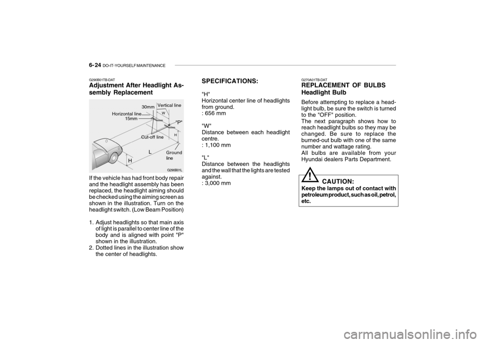
If the vehicle has had front body repair and the headlight assembly has been replaced, the headlight aiming should be checked using the aiming screen asshown in the illustration. Turn on the headlight switch. (Low Beam Position)
1. Adjust headlights so that main axis
of light is parallel to center line of the body and is aligned with point "P"shown in the illustration.
2. Dotted lines in the illustration show
the center of headlights.
G290B01TB-DAT Adjustment After Headlight As- sembly Replacement
SPECIFICATIONS: "H" Horizontal center line of headlightsfrom ground. : 656 mm "W" Distance between each headlight centre.: 1,100 mm "L" Distance between the headlights and the wall that the lights are tested against.: 3,000 mm
G290B01L
LW
H
H Cut-off line
Ground line
"P"
Horizontal line15mm
30mmVertical line
Page 173 of 191
DO-IT-YOURSELF MAINTENANCE 6- 31
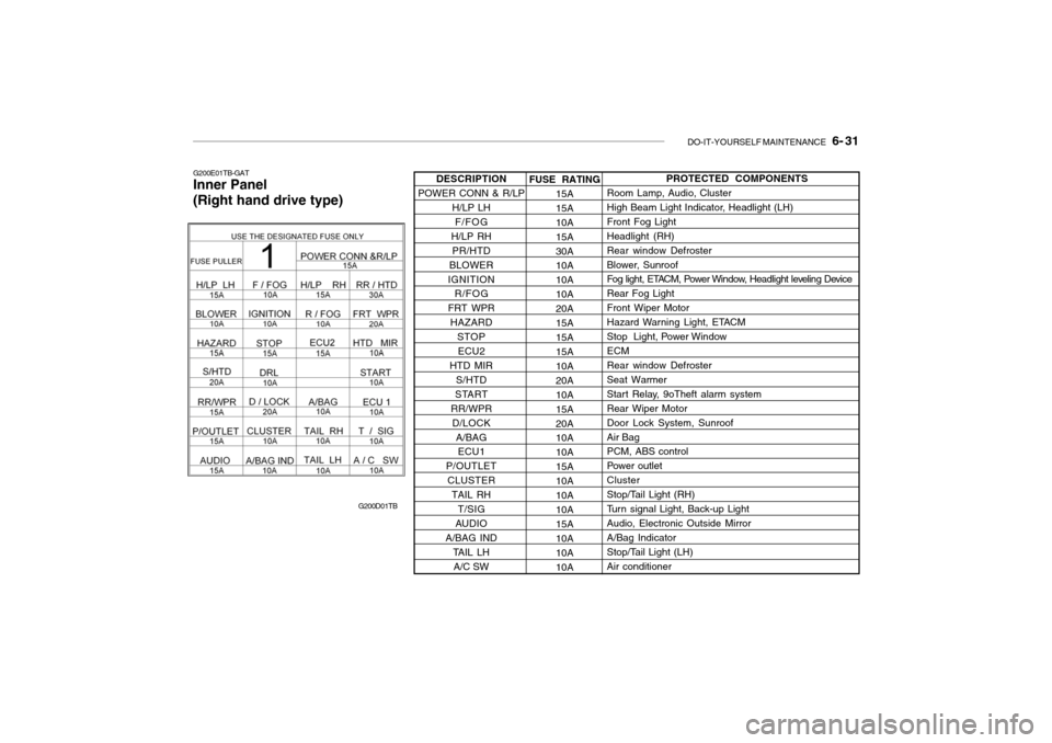
G200E01TB-GAT Inner Panel (Right hand drive type)
G200D01TBFUSE RATING15A 15A10A15A30A 10A 10A10A20A15A15A 15A 10A20A10A15A20A 10A 10A15A10A10A10A 15A 10A10A10A PROTECTED COMPONENTS
Room Lamp, Audio, Cluster
High Beam Light Indicator, Headlight (LH)Front Fog LightHeadlight (RH)Rear window Defroster
Blower, Sunroof
Fog light, ETACM, Power Window, Headlight leveling Device Rear Fog LightFront Wiper Motor
Hazard Warning Light, ETACM
Stop Light, Power WindowECM Rear window Defroster Seat Warmer
Start Relay, 9oTheft alarm systemRear Wiper MotorDoor Lock System, SunroofAir Bag PCM, ABS control
Power outletCluster
Stop/Tail Light (RH)
Turn signal Light, Back-up LightAudio, Electronic Outside Mirror A/Bag Indicator
Stop/Tail Light (LH)Air conditioner
DESCRIPTION
POWER CONN & R/LP H/LP LH
F/FOG
H/LP RH PR/HTD
BLOWER
IGNITION R/FOG
FRT WPR HAZARD STOPECU2
HTD MIR S/HTD
START
RR/WPR D/LOCK A/BAGECU1
P/OUTLET
CLUSTER TAIL RH T/SIG
AUDIO
A/BAG IND
TAIL LHA/C SW