headlight aiming Hyundai Grandeur 2004 Owner's Manual
[x] Cancel search | Manufacturer: HYUNDAI, Model Year: 2004, Model line: Grandeur, Model: Hyundai Grandeur 2004Pages: 235, PDF Size: 6.64 MB
Page 183 of 235

6. Do-It-Yourself Maintenance
Engine Compartment ..................................................................... 6-2
General Checks .............................................................................. 6-5
Checking the Engine Oil ................................................................ 6-6
Changing the Oil and Filter ........................................................... 6-7
Checking and Changing the Engine Coolant ............................... 6-8
Spark Plugs ..................................................................................6-10
Changing the Air Cleaner Filter ................................................... 6-11
Checking the Transaxle Oil (Manual) .......................................... 6-13
Checking the Transaxle Fluid (Automatic) .................................. 6-14
Checking the Brakes .................................................................... 6-15
Checking the Clutch Fluid ............................................................ 6-16
Air Conditioning Care ................................................................... 6-17
Changing the Air Filter (For Evaporator and Blower Unit) ......... 6-18
Checking Drive Belts .................................................................... 6-21
Checking and Replacing Fuses ................................................... 6-21
Power Steering Fluid Level .......................................................... 6-24
Headlight Aiming Adjustment ....................................................... 6-24
Replacement of Light Bulbs ......................................................... 6-26
Bulb Wattage ................................................................................ 6-33
Junction Box Description ............................................................. 6-34
6
Page 206 of 235

6- 24 DO-IT-YOURSELF MAINTENANCE
G240A01A-AAT
POWER STEERING HOSES
It is suggested that you check the power steering hose connections forfluid leakage at regular intervals.The power steering hoses should bereplaced if there is severe surface cracking, scuffing or worn spots. De- terioration of the hose could causepremature failure.
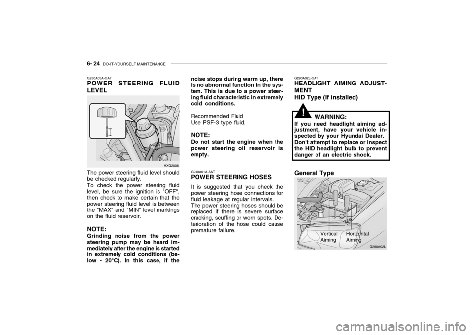
G230A03A-GAT POWER STEERING FLUID LEVEL
HXG2006
The power steering fluid level should be checked regularly. To check the power steering fluid level, be sure the ignition is "OFF", then check to make certain that the power steering fluid level is betweenthe "MAX" and "MIN" level markings on the fluid reservoir. NOTE: Grinding noise from the power steering pump may be heard im-mediately after the engine is started in extremely cold conditions (be- low - 20°C). In this case, if the noise stops during warm up, there is no abnormal function in the sys- tem. This is due to a power steer-ing fluid characteristic in extremely cold conditions.
Recommended Fluid Use PSF-3 type fluid. NOTE: Do not start the engine when the
power steering oil reservoir is empty.
G290A02L-GAT
HEADLIGHT AIMING ADJUST- MENT
HID Type (If installed)
WARNING:
If you need headlight aiming ad- justment, have your vehicle in- spected by your Hyundai Dealer. Don't attempt to replace or inspect the HID headlight bulb to prevent danger of an electric shock.
Vertical Aiming HorizontalAiming
!
G290A02L
General Type
Page 207 of 235

DO-IT-YOURSELF MAINTENANCE 6- 25
Before performing aiming adjustment,
make sure of the following.
1. Keep all tires inflated to the correct
pressure.
2. Place the vehicle on level ground
and press the front bumper & rear bumper down several times. Place the vehicle at a distance of 3 m (118 in.) from the test wall.
3. See that the vehicle is unloaded (except for full levels of coolant,engine oil and fuel, and spare tire,jack, and tools). Have the driver or equivalent weight placed in driver's seat.
4. Clean the head light lenses and
turn on the headlights (low beam).
5. Open the hood.
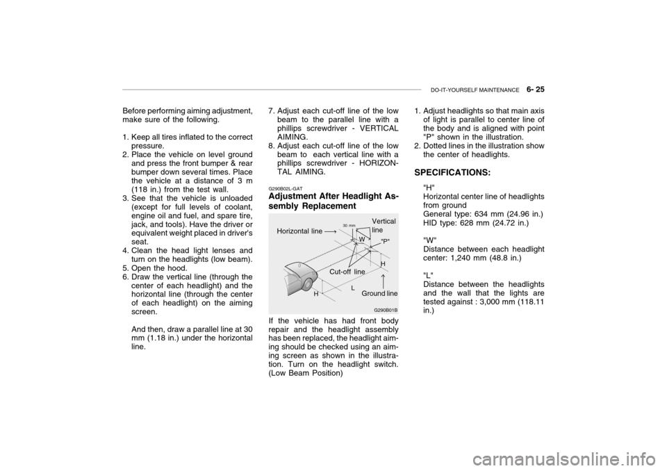
6. Draw the vertical line (through the center of each headlight) and the horizontal line (through the center of each headlight) on the aimingscreen. And then, draw a parallel line at 30 mm (1.18 in.) under the horizontal line. G290B02L-GAT
Adjustment After Headlight As- sembly Replacement
If the vehicle has had front body
repair and the headlight assembly has been replaced, the headlight aim- ing should be checked using an aim-ing screen as shown in the illustra- tion. Turn on the headlight switch. (Low Beam Position)
7. Adjust each cut-off line of the low
beam to the parallel line with aphillips screwdriver - VERTICALAIMING.
8. Adjust each cut-off line of the low
beam to each vertical line with a phillips screwdriver - HORIZON- TAL AIMING. 1. Adjust headlights so that main axis
of light is parallel to center line ofthe body and is aligned with point"P" shown in the illustration.
2. Dotted lines in the illustration show
the center of headlights.
SPECIFICATIONS: "H"Horizontal center line of headlightsfrom groundGeneral type: 634 mm (24.96 in.) HID type: 628 mm (24.72 in.) "W" Distance between each headlightcenter: 1,240 mm (48.8 in.) "L" Distance between the headlightsand the wall that the lights aretested against : 3,000 mm (118.11 in.)
G290B01B
L W
Cut-off line Ground line
"P"
Horizontal line
Vertical line30 mm
H H
Page 233 of 235

10- 4 INDEX
H Hazard Warning Syst em ........................................... 1-54
Headlight Aiming Adjustment ....................................6-25
Headlight Leveling Device Syst em ...........................1-75
Heating and Ventilation ................................. 1-80 ~ 1-93
Air flow control ..................... 1-82 ~ 1-83, 1-91 ~ 1-92
Air intake control .................. 1-81 ~ 1-82, 1-90 ~ 1-91
Bi-level heating ....................................................... 1-84
Fan speed control ........................................ 1-81, 1-90Temperature control ............................................... 1-84
High-Mounted Rear Stop Light................................. 1-69
Hood Release ........................................................... 1-70
Horn .......................................................................... 1-74
IIgnition Sw itch ............................................................. 2-3
Illuminated Ignition Switch .......................................... 1-5
Immobilizer System ........................................... 1-4 ~ 1-5
Instrument Cluster and Indicator Lights ....... 1-41 ~ 1-46
Instrument Panel Light Control (Rheo stat)............... 1-57
Intergrated Memory System (I. M. S) .......... 1-16 ~ 1-17Interior Light Interior light ................................................ 1-62 ~ 1-63
Map light .................................................... 1-61 ~ 1-62
Personal light ......................................................... 1-63
Intermittent Wiper ..................................................... 1-53
J Jump Starting .................................................... 3-2 ~ 3-3 K
Key .................................................................... 1-3 ~ 1-4
If you lose your keys ............................................. 3-12
Positions ......................................................... 2-3 ~ 2-4
L Lubrication Chart ......................................................... 9-4
Luggage Net ............................................................. 1-72
MMaintenance Intervals Explanation of scheduled maintenance items
....................................................................... 5-7 ~ 5-9
Maintenance under severe usage conditions .......... 5-6Scheduled maintenance ................................. 5-4 ~ 5-5
Service requ irements............................................... 5-2
Mirrors Day-night inside rearview ....................................... 1-65
Outside rearview mirror heater .............................. 1-64
O
Odometer ...................................................... 1-48 ~ 1-49
Outside rearview mirror ............................................ 1-64
PParking Brake ........................................................... 1-66
Passenger Presence Detec tion .............................. 1-36
Power Outle t ............................................................. 1-71
Power Seat ............................................................... 1-14