fuel cap Hyundai H-1 (Grand Starex) 2003 Owner's Manual
[x] Cancel search | Manufacturer: HYUNDAI, Model Year: 2003, Model line: H-1 (Grand Starex), Model: Hyundai H-1 (Grand Starex) 2003Pages: 173, PDF Size: 3.68 MB
Page 9 of 173
BEFORE DRIVING YOUR VEHICLE
BEFORE DRIVING YOUR VEHICLE BEFORE DRIVING YOUR VEHICLE
BEFORE DRIVING YOUR VEHICLE
BEFORE DRIVING YOUR VEHICLE
1-2
B040A01P-GAT OPERATION IN FOREIGN COUNTRIES
OPERATION IN FOREIGN COUNTRIES OPERATION IN FOREIGN COUNTRIES
OPERATION IN FOREIGN COUNTRIES
OPERATION IN FOREIGN COUNTRIES If you are going to drive your Hyundai in another
country, be sure to:
o Observe all regulations regarding registra- tion and insurance.
o Determine that acceptable fuel is available.
B050A02P-GAT VEHICLE IDENTIFICATION NUMBER
VEHICLE IDENTIFICATION NUMBER VEHICLE IDENTIFICATION NUMBER
VEHICLE IDENTIFICATION NUMBER
VEHICLE IDENTIFICATION NUMBER
(VIN)
(VIN) (VIN)
(VIN)
(VIN)
B050A01P-GAG
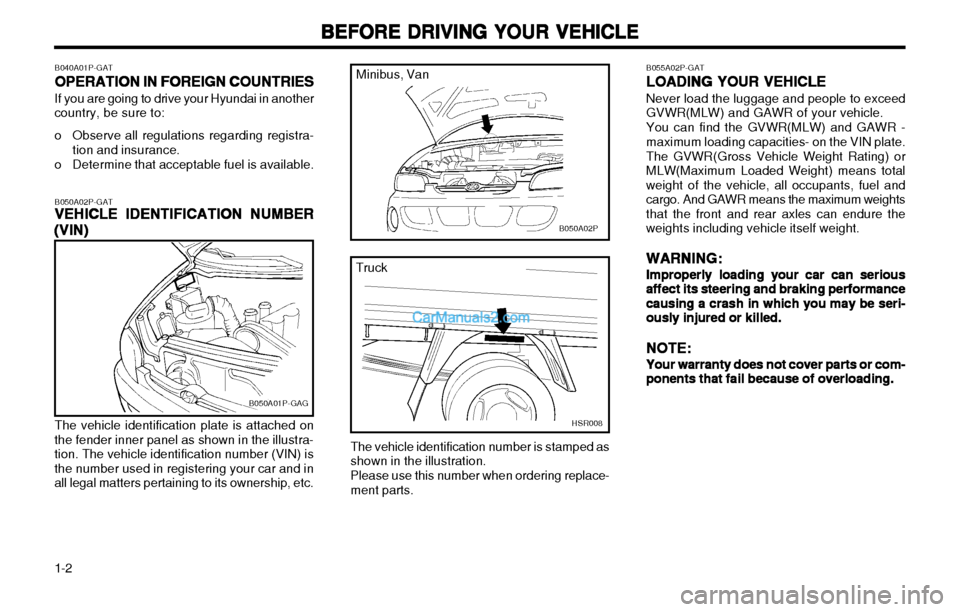
The vehicle identification plate is attached on
the fender inner panel as shown in the illustra- tion. The vehicle identification number (VIN) isthe number used in registering your car and inall legal matters pertaining to its ownership, etc.
B050A02P
Minibus, Van
HSR008
Truck
The vehicle identification number is stamped as shown in the illustration. Please use this number when ordering replace- ment parts.
B055A02P-GAT LOADING YOUR VEHICLE
LOADING YOUR VEHICLE LOADING YOUR VEHICLE
LOADING YOUR VEHICLE
LOADING YOUR VEHICLE Never load the luggage and people to exceed GVWR(MLW) and GAWR of your vehicle. You can find the GVWR(MLW) and GAWR - maximum loading capacities- on the VIN plate. The GVWR(Gross Vehicle Weight Rating) or MLW(Maximum Loaded Weight) means totalweight of the vehicle, all occupants, fuel andcargo. And GAWR means the maximum weightsthat the front and rear axles can endure theweights including vehicle itself weight.
WARNING:
WARNING: WARNING:
WARNING:
WARNING:
Improperly loading your car can serious
Improperly loading your car can serious Improperly loading your car can serious
Improperly loading your car can serious
Improperly loading your car can serious
affect its steering and braking performance
affect its steering and braking performance affect its steering and braking performance
affect its steering and braking performance
affect its steering and braking performance
causing a crash in which you may be seri-
causing a crash in which you may be seri- causing a crash in which you may be seri-
causing a crash in which you may be seri-
causing a crash in which you may be seri-
ously injured or killed.
ously injured or killed. ously injured or killed.
ously injured or killed.
ously injured or killed.
NOTE:
NOTE: NOTE:
NOTE:
NOTE:
Your warranty does not cover parts or com-
Your warranty does not cover parts or com- Your warranty does not cover parts or com-
Your warranty does not cover parts or com-
Your warranty does not cover parts or com-
ponents that fail because of overloading.
ponents that fail because of overloading. ponents that fail because of overloading.
ponents that fail because of overloading.
ponents that fail because of overloading.
Page 11 of 173
BEFORE DRIVING YOUR VEHICLE
BEFORE DRIVING YOUR VEHICLE BEFORE DRIVING YOUR VEHICLE
BEFORE DRIVING YOUR VEHICLE
BEFORE DRIVING YOUR VEHICLE
1-4 B100A02P-GAT
TT
TT
T HE USE OF KEYS
HE USE OF KEYS HE USE OF KEYS
HE USE OF KEYS
HE USE OF KEYS
B100A01P-GAG
23
5,6 1
4
B100B01P
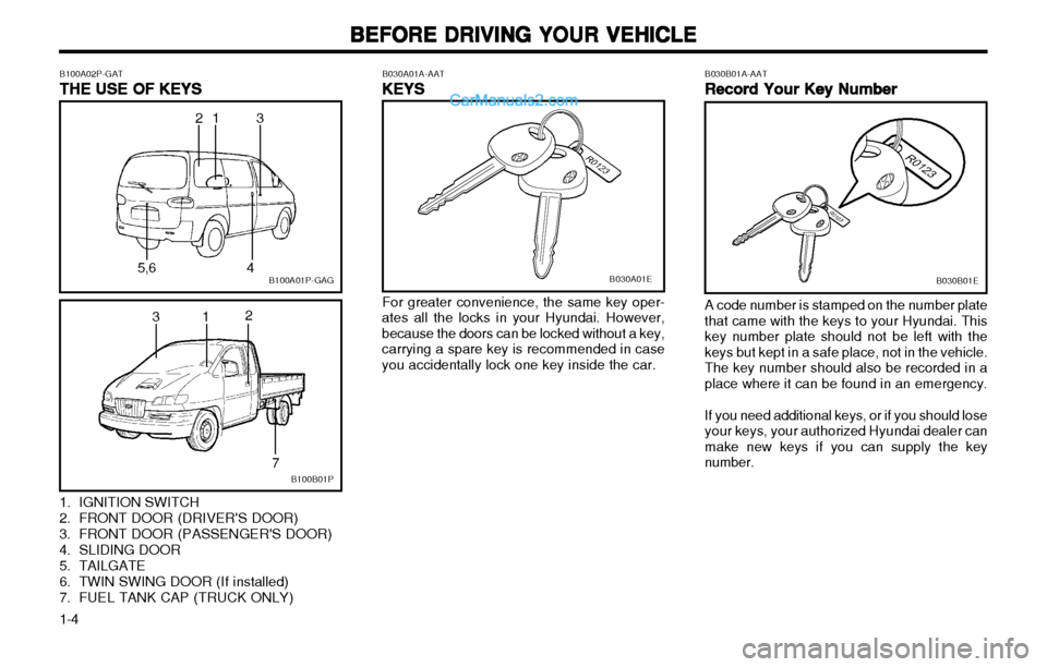
1. IGNITION SWITCH
2. FRONT DOOR (DRIVER'S DOOR)
3. FRONT DOOR (PASSENGER'S DOOR)
4. SLIDING DOOR
5. TAILGATE
6. TWIN SWING DOOR (If installed)
7. FUEL TANK CAP (TRUCK ONLY)
31 2
7
B030A01E
B030A01A-AAT
KEYS
KEYS KEYS
KEYS
KEYS For greater convenience, the same key oper-
ates all the locks in your Hyundai. However, because the doors can be locked without a key,carrying a spare key is recommended in caseyou accidentally lock one key inside the car. B030B01A-AAT
Record Your Key Number
Record Your Key Number Record Your Key Number
Record Your Key Number
Record Your Key NumberB030B01E
A code number is stamped on the number plate that came with the keys to your Hyundai. Thiskey number plate should not be left with thekeys but kept in a safe place, not in the vehicle.The key number should also be recorded in aplace where it can be found in an emergency. If you need additional keys, or if you should lose your keys, your authorized Hyundai dealer canmake new keys if you can supply the keynumber.
Page 23 of 173
BEFORE DRIVING YOUR VEHICLE
BEFORE DRIVING YOUR VEHICLE BEFORE DRIVING YOUR VEHICLE
BEFORE DRIVING YOUR VEHICLE
BEFORE DRIVING YOUR VEHICLE
1-16 B210A01P-GAT
REAR SIDE, QUARTER WINDOW
REAR SIDE, QUARTER WINDOW REAR SIDE, QUARTER WINDOW
REAR SIDE, QUARTER WINDOW
REAR SIDE, QUARTER WINDOW
Hinged window (Minibus)
Hinged window (Minibus) Hinged window (Minibus)
Hinged window (Minibus)
Hinged window (Minibus)
To open
To open To open
To open
To open
B210A01P-GAG
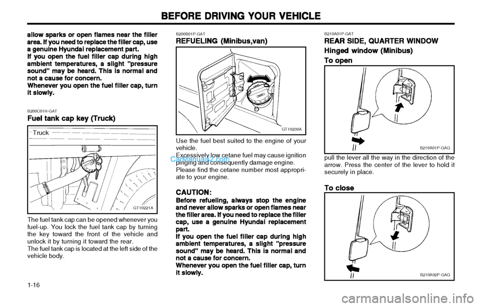
pull the lever all the way in the direction of the arrow. Press the center of the lever to hold itsecurely in place.
To close
To close To close
To close
To close
B210A02P-GAG
B200B01P-GAT
RR
RR
R EFUELING
EFUELING EFUELING
EFUELING
EFUELING (Minibus,van)
(Minibus,van) (Minibus,van)
(Minibus,van)
(Minibus,van)
GT10230A
Use the fuel best suited to the engine of your vehicle. Excessively low cetane fuel may cause ignition pinging and consequently damage engine. Please find the cetane number most appropri- ate to your engine.
CAUTION:
CAUTION: CAUTION:
CAUTION:
CAUTION:
Before refueling, always stop the engine
Before refueling, always stop the engine Before refueling, always stop the engine
Before refueling, always stop the engine
Before refueling, always stop the engine
and never allow sparks or open flames near
and never allow sparks or open flames near and never allow sparks or open flames near
and never allow sparks or open flames near
and never allow sparks or open flames near
the filler area. If you need to replace the filler
the filler area. If you need to replace the filler the filler area. If you need to replace the filler
the filler area. If you need to replace the filler
the filler area. If you need to replace the filler
cap, use a genuine Hyundai replacement
cap, use a genuine Hyundai replacement cap, use a genuine Hyundai replacement
cap, use a genuine Hyundai replacement
cap, use a genuine Hyundai replacement
part.
part. part.
part.
part.
If you open the fuel filler cap during high
If you open the fuel filler cap during high If you open the fuel filler cap during high
If you open the fuel filler cap during high
If you open the fuel filler cap during high
ambient temperatures, a slight "pressure
ambient temperatures, a slight "pressure ambient temperatures, a slight "pressure
ambient temperatures, a slight "pressure
ambient temperatures, a slight "pressure
sound" may be heard. This is normal and
sound" may be heard. This is normal and sound" may be heard. This is normal and
sound" may be heard. This is normal and
sound" may be heard. This is normal and
not a cause for concern.
not a cause for concern. not a cause for concern.
not a cause for concern.
not a cause for concern.
Whenever you open the fuel filler cap, turn
Whenever you open the fuel filler cap, turn Whenever you open the fuel filler cap, turn
Whenever you open the fuel filler cap, turn
Whenever you open the fuel filler cap, turn
it slowly.
it slowly. it slowly.
it slowly.
it slowly.
The fuel tank cap can be opened whenever you
fuel-up. You lock the fuel tank cap by turningthe key toward the front of the vehicle andunlock it by turning it toward the rear.
The fuel tank cap is located at the left side of the
vehicle body. B200C01H-GAT
Fuel tank cap key (Truck)
Fuel tank cap key (Truck) Fuel tank cap key (Truck)
Fuel tank cap key (Truck)
Fuel tank cap key (Truck)
GT10221A
Truck
allow sparks or open flames near the filler
allow sparks or open flames near the filler allow sparks or open flames near the filler
allow sparks or open flames near the filler
allow sparks or open flames near the filler
area. If you need to replace the filler cap, use
area. If you need to replace the filler cap, use area. If you need to replace the filler cap, use
area. If you need to replace the filler cap, use
area. If you need to replace the filler cap, use
a genuine Hyundai replacement part.
a genuine Hyundai replacement part. a genuine Hyundai replacement part.
a genuine Hyundai replacement part.
a genuine Hyundai replacement part.
If you open the fuel filler cap during high
If you open the fuel filler cap during high If you open the fuel filler cap during high
If you open the fuel filler cap during high
If you open the fuel filler cap during high ambient temperatures, a slight "pressure
ambient temperatures, a slight "pressure ambient temperatures, a slight "pressure
ambient temperatures, a slight "pressure
ambient temperatures, a slight "pressure
sound" may be heard. This is normal and
sound" may be heard. This is normal and sound" may be heard. This is normal and
sound" may be heard. This is normal and
sound" may be heard. This is normal and
not a cause for concern.
not a cause for concern. not a cause for concern.
not a cause for concern.
not a cause for concern.
Whenever you open the fuel filler cap, turn
Whenever you open the fuel filler cap, turn Whenever you open the fuel filler cap, turn
Whenever you open the fuel filler cap, turn
Whenever you open the fuel filler cap, turnit slowly.
it slowly. it slowly.
it slowly.
it slowly.
Page 128 of 173
IN CASE OF EMERGENCY
IN CASE OF EMERGENCY IN CASE OF EMERGENCY
IN CASE OF EMERGENCY
IN CASE OF EMERGENCY
4-13
E090A01P-GATBLEEDING THE FUEL SYSTEM
BLEEDING THE FUEL SYSTEM BLEEDING THE FUEL SYSTEM
BLEEDING THE FUEL SYSTEM
BLEEDING THE FUEL SYSTEM
E090A01P
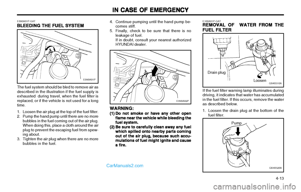
The fuel system should be bled to remove air as described in the illustration if the fuel supply isexhausted during travel, when the fuel filter isreplaced, or if the vehicle is not used for a longtime.
1. Loosen the air plug at the top of the fuel filter.
2. Pump the hand pump until there are no more bubbles in the fuel coming out of the air plug. When doing this, place a cloth around the airplug to prevent the escaping fuel from spew-ing about.
3. Tighten the air plug when there are no more bubbles in the fuel.
E100A01P-GATREMOVAL OF WATER FROM THE
REMOVAL OF WATER FROM THE REMOVAL OF WATER FROM THE
REMOVAL OF WATER FROM THE
REMOVAL OF WATER FROM THE
FUEL FILTER
FUEL FILTER FUEL FILTER
FUEL FILTER
FUEL FILTER
GS40310ALoosen
Drain plug
If the fuel filter warning lamp illuminates during driving, it indicates that water has accumulatedin the fuel filter. If this occurs, remove the wateras described below.
1. Loosen the drain plug at the bottom of the fuel filter.
GS40320A
Pump
4. Continue pumping until the hand pump be-
comes stiff.
5. Finally, check to be sure that there is no leakage of fuel. If in doubt, consult your nearest authorized HYUNDAI dealer.
WARNING:
WARNING: WARNING:
WARNING:
WARNING:
(1)(1)
(1)(1)
(1) Do not smoke or have any other open
Do not smoke or have any other open Do not smoke or have any other open
Do not smoke or have any other open
Do not smoke or have any other open
flame near the vehicle while bleeding the
flame near the vehicle while bleeding the flame near the vehicle while bleeding the
flame near the vehicle while bleeding the
flame near the vehicle while bleeding the
fuel system.
fuel system. fuel system.
fuel system.
fuel system.
(2)(2)
(2)(2)
(2) Be sure to carefully clean away any fuel
Be sure to carefully clean away any fuel Be sure to carefully clean away any fuel
Be sure to carefully clean away any fuel
Be sure to carefully clean away any fuel
which spilled onto nearby parts coming
which spilled onto nearby parts coming which spilled onto nearby parts coming
which spilled onto nearby parts coming
which spilled onto nearby parts coming
out of the air plug, because such accu-
out of the air plug, because such accu- out of the air plug, because such accu-
out of the air plug, because such accu-
out of the air plug, because such accu-
mulations of fuel might ignite and cause
mulations of fuel might ignite and cause mulations of fuel might ignite and cause
mulations of fuel might ignite and cause
mulations of fuel might ignite and cause
a fire.
a fire. a fire.
a fire.
a fire.
E090A02P
Page 129 of 173
IN CASE OF EMERGENCY
IN CASE OF EMERGENCY IN CASE OF EMERGENCY
IN CASE OF EMERGENCY
IN CASE OF EMERGENCY
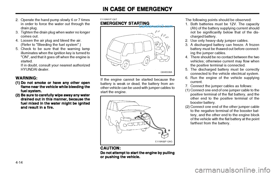
4-14 The following points should be observed:
1. Both batteries must be 12V. The capacity
(Ah) of the battery supplying current should not be significantly below that of the dis-charged battery.
2. Use only heavy-duty jumper cables.
3. A discharged battery can freeze. A frozen battery must be thawed out before connect- ing the jumper cables.
4. There should be no contact between the two vehicles; otherwise current may flow whenthe positive terminal is connected.
5. The discharged battery must be correctly connected to the vehicle electrical system.
6. Run the engine of the vehicle supplying current.
7. Connect the jumper cables as follows:
(1) Connect one end of one jumper cable to the positive terminal of the flat battery, and the other end to the positive terminal of thebooster battery.
(2) Connect one end of the other jumper cable to the negative terminal of the booster bat-tery, and the other end to the engine blockof the vehicle with the flat battery at the pointfarthest from the battery.
GS40330A
E110A02P-GAG
If the engine cannot be started because the battery is weak or dead, the battery from an-other vehicle can be used with jumper cables tostart the engine.
E110A01P-GAT
EMERGENCY STARTING
EMERGENCY STARTING EMERGENCY STARTING
EMERGENCY STARTING
EMERGENCY STARTING
CAUTION:
CAUTION: CAUTION:
CAUTION:
CAUTION:
Do not attempt to start the engine by pulling
Do not attempt to start the engine by pulling Do not attempt to start the engine by pulling
Do not attempt to start the engine by pulling
Do not attempt to start the engine by pulling
or pushing the vehicle.
or pushing the vehicle. or pushing the vehicle.
or pushing the vehicle.
or pushing the vehicle.
2. Operate the hand pump slowly 6 or 7 times
in order to force the water out through thedrain plug.
3. Tighten the drain plug when water no longer comes out.
4. Loosen the air plug and bleed the air. (Refer to "Bleeding the fuel system".)
5. Check to be sure that the warning lamp illuminates when the ignition key is turned to"ON", and that it goes off when the engine isstarted.If in doubt, consult your nearest authorizedHYUNDAI dealer.
WARNING:
WARNING: WARNING:
WARNING:
WARNING:
(1)(1)
(1)(1)
(1) Do not smoke or have any other open
Do not smoke or have any other open Do not smoke or have any other open
Do not smoke or have any other open
Do not smoke or have any other open
flame near the vehicle while bleeding the
flame near the vehicle while bleeding the flame near the vehicle while bleeding the
flame near the vehicle while bleeding the
flame near the vehicle while bleeding the
fuel system.
fuel system. fuel system.
fuel system.
fuel system.
(2)(2)
(2)(2)
(2) Be sure to carefully wipe away any water
Be sure to carefully wipe away any water Be sure to carefully wipe away any water
Be sure to carefully wipe away any water
Be sure to carefully wipe away any water
drained out in this manner, because the
drained out in this manner, because the drained out in this manner, because the
drained out in this manner, because the
drained out in this manner, because the
fuel mixed in the water might be ignited
fuel mixed in the water might be ignited fuel mixed in the water might be ignited
fuel mixed in the water might be ignited
fuel mixed in the water might be ignited
and result in a fire.
and result in a fire. and result in a fire.
and result in a fire.
and result in a fire.
Page 132 of 173
IN CASE OF EMERGENCY
IN CASE OF EMERGENCY IN CASE OF EMERGENCY
IN CASE OF EMERGENCY
IN CASE OF EMERGENCY
4-17
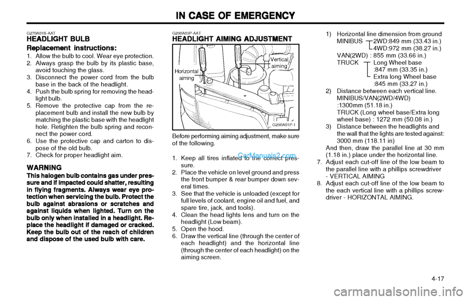
1) Horizontal line dimension from ground
MINIBUS 2WD:849 mm (33.43 in.) 4WD:972 mm (38.27 in.)
VAN(2WD) : 855 mm (33.66 in.)
TRUCK Long Wheel base
:847 mm (33.35 in.)Extra long Wheel base:845 mm (33.27 in.)
2) Distance between each vertical line.
MINIBUS/VAN(2WD/4WD):1300mm (51.18 in.)
TRUCK (Long wheel base/Extra long
wheel base) : 1272 mm (50.08 in.)
3) Distance between the headlights and the wall that the lights are tested against: 3000 mm (118.11 in)
And then, draw the parallel line at 30 mm (1.18 in.) place under the horizontal line.
7. Adjust each cut-off line of the low beam to the parallel line with a phillips screwdriver - VERTICAL AIMING
8. Adjust each cut-off line of the low beam to the each vertical line with a phillips screw- driver - HORIZONTAL AIMING.
G290A03P-AATHEADLIGHT AIMING ADJUSTMENT
HEADLIGHT AIMING ADJUSTMENT HEADLIGHT AIMING ADJUSTMENT
HEADLIGHT AIMING ADJUSTMENT
HEADLIGHT AIMING ADJUSTMENT
G290A01P-1
Before performing aiming adjustment, make sure of the following.
1. Keep all tires inflated to the correct pres- sure.
2. Place the vehicle on level ground and press the front bumper & rear bumper down sev-eral times.
3. See that the vehicle is unloaded (except for full levels of coolant, engine oil and fuel, andspare tire, jack, and tools).
4. Clean the head lights lens and turn on the headlight (Low beam).
5. Open the hood.
6. Draw the vertical line (through the center of each headlight) and the horizontal line (through the center of each headlight) on theaiming screen.
Horizontalaiming
Verticalaiming
G270A01S-AAT
HEADLIGHT BULB
HEADLIGHT BULB HEADLIGHT BULB
HEADLIGHT BULB
HEADLIGHT BULB
Replacement instructions:
Replacement instructions: Replacement instructions:
Replacement instructions:
Replacement instructions:
1. Allow the bulb to cool. Wear eye protection.
2. Always grasp the bulb by its plastic base,
avoid touching the glass.
3. Disconnect the power cord from the bulb base in the back of the headlight.
4. Push the bulb spring for removing the head- light bulb.
5. Remove the protective cap from the re- placement bulb and install the new bulb by matching the plastic base with the headlighthole. Retighten the bulb spring and recon-nect the power cord.
6. Use the protective cap and carton to dis- pose of the old bulb.
7. Check for proper headlight aim.
WARNING
WARNING WARNING
WARNING
WARNING
This halogen bulb contains gas under pres-
This halogen bulb contains gas under pres- This halogen bulb contains gas under pres-
This halogen bulb contains gas under pres-
This halogen bulb contains gas under pres- sure and if impacted could shatter, resulting
sure and if impacted could shatter, resulting sure and if impacted could shatter, resulting
sure and if impacted could shatter, resulting
sure and if impacted could shatter, resulting
in flying fragments. Always wear eye pro-
in flying fragments. Always wear eye pro- in flying fragments. Always wear eye pro-
in flying fragments. Always wear eye pro-
in flying fragments. Always wear eye pro-
tection when servicing the bulb. Protect the
tection when servicing the bulb. Protect the tection when servicing the bulb. Protect the
tection when servicing the bulb. Protect the
tection when servicing the bulb. Protect the
bulb against abrasions or scratches and
bulb against abrasions or scratches and bulb against abrasions or scratches and
bulb against abrasions or scratches and
bulb against abrasions or scratches and
against liquids when lighted. Turn on the
against liquids when lighted. Turn on the against liquids when lighted. Turn on the
against liquids when lighted. Turn on the
against liquids when lighted. Turn on the
bulb only when installed in a headlight. Re-
bulb only when installed in a headlight. Re- bulb only when installed in a headlight. Re-
bulb only when installed in a headlight. Re-
bulb only when installed in a headlight. Re-
place the headlight if damaged or cracked.
place the headlight if damaged or cracked. place the headlight if damaged or cracked.
place the headlight if damaged or cracked.
place the headlight if damaged or cracked.
Keep the bulb out of the reach of children
Keep the bulb out of the reach of children Keep the bulb out of the reach of children
Keep the bulb out of the reach of children
Keep the bulb out of the reach of children
and dispose of the used bulb with care.
and dispose of the used bulb with care. and dispose of the used bulb with care.
and dispose of the used bulb with care.
and dispose of the used bulb with care.
Page 146 of 173
6-9
PREVENTIVE MAINTENANCE
PREVENTIVE MAINTENANCE PREVENTIVE MAINTENANCE
PREVENTIVE MAINTENANCE
PREVENTIVE MAINTENANCE
G080F01P-GAToo
oo
o
Fuel hose, vapor hose and fuel
Fuel hose, vapor hose and fuel Fuel hose, vapor hose and fuel
Fuel hose, vapor hose and fuel
Fuel hose, vapor hose and fuel
filler cap
filler cap filler cap
filler cap
filler cap
The fuel hose, vapor hose and fuel filler cap
should be inspected at those intervals specified in the maintenance schedule. Make sure that anew fuel hose, vapor hose or fuel filler cap iscorrectly replaced. Consult your Hyundai dealerif you have any questions.
G080G01P-GAToo
oo
o Air cleaner filter
Air cleaner filter Air cleaner filter
Air cleaner filter
Air cleaner filter
A genuine Hyundai part is recommended forreplacement of the air cleaner filter. G080H01P-GAT
oo
oo
o Spark plugs
Spark plugs Spark plugs
Spark plugs
Spark plugs
Make sure to install new spark plugs of the correct heat range. G080I01P-GAT
oo
oo
o
Drive belts
Drive belts Drive belts
Drive belts
Drive belts
Inspect all drive belts (water pump and alterna- tor) for evidence of cuts, cracks, excessivewear or oiliness, and replace if necessary.Drive belts should be checked periodically forproper tension and adjusted as necessary.
G080D01P-GAT
oo
oo
o Fuel filter
Fuel filter Fuel filter
Fuel filter
Fuel filter
A clogged filter can limit the speed at which the
vehicle may be driven, damage the emissionsystem and cause hard starting. If an exces-sive amount of foreign matter accumulates inthe fuel tank, the filter may require replacementmore frequently.
After installing a new filter, run the engine for
several minutes, and check for leaks at theconnections.
G080A01P-GAT
EXPLANATION OF SCHEDULED
EXPLANATION OF SCHEDULED EXPLANATION OF SCHEDULED
EXPLANATION OF SCHEDULED
EXPLANATION OF SCHEDULED
MAINTENANCE ITEMS
MAINTENANCE ITEMS MAINTENANCE ITEMS
MAINTENANCE ITEMS
MAINTENANCE ITEMS
oo
oo
o
Engine oil and filter
Engine oil and filter Engine oil and filter
Engine oil and filter
Engine oil and filter
The engine oil and filter should be changed at
those intervals specified in the maintenanceschedule. If the vehicle is being driven in se-vere conditions, more frequent oil and filterchanges are required.
G080B01P-GAT oo
oo
o Valve clearances (DIESEL)
Valve clearances (DIESEL) Valve clearances (DIESEL)
Valve clearances (DIESEL)
Valve clearances (DIESEL)
An incorrect valve clearance will not only result
in rough engine operation, but will also causeexcessive noise and reduced engine output.
Inspect valve clearance and adjust as required
while the engine is hot.
Valve-to-rocker arm clearance:
Valve-to-rocker arm clearance: Valve-to-rocker arm clearance:
Valve-to-rocker arm clearance:
Valve-to-rocker arm clearance: DIESEL:
Hot ............................ 0.25 mm (0.0098 in.) Cold ............................ 0.15 mm (0.0059 in.)
G080C01P-GAT oo
oo
o Fuel lines and connections
Fuel lines and connections Fuel lines and connections
Fuel lines and connections
Fuel lines and connections
Check the fuel lines and connections for leak-
age and damage. Replace any damaged or leaking parts immediately. G080E01P-GAT
oo
oo
o Vacuum and crankcase
Vacuum and crankcase Vacuum and crankcase
Vacuum and crankcase
Vacuum and crankcase
ventilation hoses
ventilation hoses ventilation hoses
ventilation hoses
ventilation hoses
Inspect the surface of hoses for evidence of
heat and/or mechanical damage. Hard andbrittle rubber, cracking, tears, cuts, abrasions,and excessive swelling indicate deterioration.Particular attention should be paid to examiningthose hose surfaces nearest to high heatsources, such as the exhaust manifold.
Inspect the hose routing to assure that the
hoses do not come in contact with any heatsource, sharp edges or moving componentwhich might cause heat damage or mechanicalwear. Inspect all hose connections, such asclamps and couplings, to make sure they aresecure, and that no leaks are present. Hosesshould be replaced immediately if there is anyevidence of deterioration or damage.
Page 148 of 173
7-1
EMISSION CONTROL SYSTEM
EMISSION CONTROL SYSTEM EMISSION CONTROL SYSTEM
EMISSION CONTROL SYSTEM
EMISSION CONTROL SYSTEM
H030A01P-GAT2.2.
2.2.
2.
EE
EE
E
VAPORATIVE
VAPORATIVE VAPORATIVE
VAPORATIVE
VAPORATIVE E
E E
E
E MISSION CON-
MISSION CON- MISSION CON-
MISSION CON-
MISSION CON-
TROL
TROL TROL
TROL
TROL SS
SS
S YSTEM
YSTEM YSTEM
YSTEM
YSTEM (
( (
(
( EE
EE
E xcept canister)
xcept canister) xcept canister)
xcept canister)
xcept canister)
The Evaporative Emission Control System is
designed to prevent fuel vapors from escaping into the atmosphere.
If the fuel-vapor vent line is clogged or dam-
aged, the fuel-vapor mixture will escape intothe atmosphere and cause insufficient emis-sion control. Disconnect the line at both ends, and blow it
clean with compressed air.
Remove the filler cap from the filler pipe, and
check to see if there is evidence that thepacking contact to the filler pipe is faulty. Theoverfill limiter (2-way valve) installed on thevapor line between the canister inlet and fueltank outlet must be checked for correct opera-tion. H050A01P-GAT
3.3.
3.3.
3.
EXHAUST EMISSION CONTROL
EXHAUST EMISSION CONTROL EXHAUST EMISSION CONTROL
EXHAUST EMISSION CONTROL
EXHAUST EMISSION CONTROL
SYSTEM
SYSTEM SYSTEM
SYSTEM
SYSTEM
The Exhaust Emission Control System is a
highly effective system which controls exhaustemission while maintaining good vehicle per-formance.
H060A01P-GATCC
CC
C
atalytic Converter
atalytic Converter atalytic Converter
atalytic Converter
atalytic Converter
All Hyundai vehicles are equipped with a mono-
lith type three-way catalytic converter to re-duce the carbon monoxide, hydrocarbons andnitrogen oxides contained in the exhaust gas.
H000A01P-GAT
7.7.
7.7.
7.
EMISSION CON-
EMISSION CON- EMISSION CON-
EMISSION CON-
EMISSION CON-
TROL SYSTEM
TROL SYSTEM TROL SYSTEM
TROL SYSTEM
TROL SYSTEM
H010A01P-GAT EMISSION CONTROL SYSTEM
EMISSION CONTROL SYSTEM EMISSION CONTROL SYSTEM
EMISSION CONTROL SYSTEM
EMISSION CONTROL SYSTEM
(Gasoline)
(Gasoline) (Gasoline)
(Gasoline)
(Gasoline) Your Hyundai is equipped with an emission
control system. There are three emission control systems which
are as follows.
(1) Crankcase emission control system (2) Evaporative emission control system(3) Exhaust emission control system In order to assure the proper function of the
emission control systems, it is recommended that you have your vehicle inspected and main-tained by an authorized Hyundai dealer in ac-cordance with the maintenance schedule inthis manual.
H020A01P-GAT1.1.
1.1.
1.
CRANKCASE EMISSION CONTROL
CRANKCASE EMISSION CONTROL CRANKCASE EMISSION CONTROL
CRANKCASE EMISSION CONTROL
CRANKCASE EMISSION CONTROL
SYSTEM
SYSTEM SYSTEM
SYSTEM
SYSTEM
The positive crankcase ventilation system is
employed to prevent air pollution caused byblow-by gases being emitted from the crank-case. This system supplies fresh air to thecrankcase through the air cleaner. Inside thecrankcase, the fresh air mixes with blow-bygases, then passes through the PCV valve intothe induction system. H080A01P-GAT
PCV Valve
PCV Valve PCV Valve
PCV Valve
PCV Valve
The crankcase ventilation system must be kept
clean to maintain good engine performance.
Periodic servicing is required to remove com-
bustion products from the PCV valve. H040A01P-GAT
Canister
Canister Canister
Canister
Canister While the engine is inoperative, fuel vapors
generated inside the fuel tank are absorbed and stored in the canister. When the engine isrunning, the fuel vapors absorbed in the canis-ter are drawn into the induction system throughthe purge control solenoid valve.
H090A01P-GATPurge Control Solenoid Valve
Purge Control Solenoid Valve Purge Control Solenoid Valve
Purge Control Solenoid Valve
Purge Control Solenoid Valve
The purge control solenoid valve is controlled
by the ECU; when the engine coolant tempera-ture is low, and during idling, it closes, so thatevaporated fuel is not taken into the surge tank.After engine warm-up, during ordinary driving, it opens so as to introduce evaporated fuel to the surge tank.
77
77
7
Page 149 of 173
EMISSION CONTROL SYSTEM
EMISSION CONTROL SYSTEM EMISSION CONTROL SYSTEM
EMISSION CONTROL SYSTEM
EMISSION CONTROL SYSTEM
7-2
H100A01P-GAT
Vacuum Hoses, Crankcase Ventilation
Vacuum Hoses, Crankcase Ventilation Vacuum Hoses, Crankcase Ventilation
Vacuum Hoses, Crankcase Ventilation
Vacuum Hoses, Crankcase Ventilation
Hoses and Water Hoses
Hoses and Water Hoses Hoses and Water Hoses
Hoses and Water Hoses
Hoses and Water Hoses Inspect the surface of hoses for evidence of heat and mechanical damage. Hard and brittle rubber, cracking, checking, tears, cuts, abrasions, and excessive swellingindicate deterioration of the rubber.Particular attention should be paid to examin-ing those surfaces nearest to high heat sources,such as the exhaust manifold. Inspect the hose routing to assure that the hoses do not come in contact with any heatsource or moving component which might causeheat damage or mechanical wear. Inspect allhose connections, such as clamps and cou-plings, to make sure they are secure and thatno leaks are present. Hoses should be re-placed immediately if there is any evidence ofdeterioration or damage. H110A01P-GAT
Fuel System (tank, pipe line, connec-
Fuel System (tank, pipe line, connec- Fuel System (tank, pipe line, connec-
Fuel System (tank, pipe line, connec-
Fuel System (tank, pipe line, connec-
tions and fuel filler cap)
tions and fuel filler cap) tions and fuel filler cap)
tions and fuel filler cap)
tions and fuel filler cap)
Check for damage or leakage in the fuel lines
and connections. Check for damage and loose-ness of fuel filler cap. Particular attention shouldbe paid to examine those fuel lines nearest tohigh heat sources such as the exhaust mani-fold.
H120A01P-GATDistributor Cap, Rotor and Spark Ad-
Distributor Cap, Rotor and Spark Ad- Distributor Cap, Rotor and Spark Ad-
Distributor Cap, Rotor and Spark Ad-
Distributor Cap, Rotor and Spark Ad-
vancer System
vancer System vancer System
vancer System
vancer System
Check the distributor cap, rotor and spark ad-
vancer system to maintain driveability and goodexhaust gas.
Page 156 of 173
8-7
CONSUMER INFORMATION
CONSUMER INFORMATION CONSUMER INFORMATION
CONSUMER INFORMATION
CONSUMER INFORMATION
( 9 ) Fuel, engine coolant, oil and exhaust gas leakage
(10) Exterior and interior lamp operation (11) Meter, gauge, and indication/warning lamp operation
(12) Steering wheel free play(13) Clutch pedal free play (14) Brake pedal free play (15) Parking brake lever stroke
Others
Others Others
Others
Others
(1) Wheel rotation
(1) Wheel rotation (1) Wheel rotation
(1) Wheel rotation
(1) Wheel rotation
Every 20,000km (12,000miles)or 12
Every 20,000km (12,000miles)or 12 Every 20,000km (12,000miles)or 12
Every 20,000km (12,000miles)or 12
Every 20,000km (12,000miles)or 12
months, whichever comes first
months, whichever comes first months, whichever comes first
months, whichever comes first
months, whichever comes first
(2) Hinge and latch lubrication
(2) Hinge and latch lubrication (2) Hinge and latch lubrication
(2) Hinge and latch lubrication
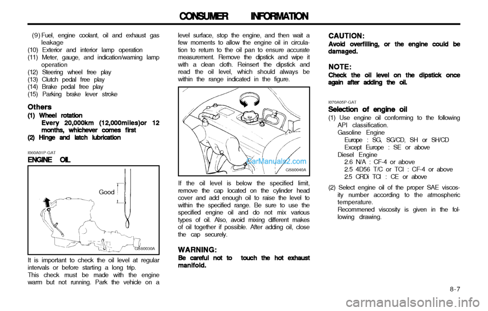
(2) Hinge and latch lubrication level surface, stop the engine, and then wait a few moments to allow the engine oil in circula-tion to return to the oil pan to ensure accuratemeasurement. Remove the dipstick and wipe itwith a clean cloth. Reinsert the dipstick andread the oil level, which should always bewithin the range indicated in the figure.
GS80030A
Good
I060A01P-GAT
ENGINE OIL
ENGINE OIL ENGINE OIL
ENGINE OIL
ENGINE OIL
It is important to check the oil level at regular
intervals or before starting a long trip.
This check must be made with the engine
warm but not running. Park the vehicle on a
GS80040A
If the oil level is below the specified limit,
remove the cap located on the cylinder head cover and add enough oil to raise the level towithin the specified range. Be sure to use thespecified engine oil and do not mix varioustypes of oil. Also, avoid mixing different makesof oil together if possible. After adding oil, closethe cap securely.
WARNING:
WARNING: WARNING:
WARNING:
WARNING:
Be careful not to touch the hot exhaust
Be careful not to touch the hot exhaust Be careful not to touch the hot exhaust
Be careful not to touch the hot exhaust
Be careful not to touch the hot exhaust manifold.
manifold. manifold.
manifold.
manifold. CAUTION:
CAUTION: CAUTION:
CAUTION:
CAUTION:
Avoid overfilling, or the engine could be
Avoid overfilling, or the engine could be Avoid overfilling, or the engine could be
Avoid overfilling, or the engine could be
Avoid overfilling, or the engine could bedamaged.
damaged. damaged.
damaged.
damaged.
NOTE:
NOTE: NOTE:
NOTE:
NOTE:
Check the oil level on the dipstick once
Check the oil level on the dipstick once Check the oil level on the dipstick once
Check the oil level on the dipstick once
Check the oil level on the dipstick onceagain after adding the oil.
again after adding the oil. again after adding the oil.
again after adding the oil.
again after adding the oil.
I070A05P-GATSelection of engine oil
Selection of engine oil Selection of engine oil
Selection of engine oil
Selection of engine oil (1) Use engine oil conforming to the following
API classification. Gasoline Engine
Europe : SG, SG/CD, SH or SH/CDExcept Europe : SE or above
Diesel Engine 2.6 N/A : CF-4 or above2.5 4D56 T/C or TCI : CF-4 or above
2.5 CRDi TCI : CE or above
(2) Select engine oil of the proper SAE viscos- ity number according to the atmospheric temperature. Recommened viscosity is given in the fol- lowing drawing.