air filter Hyundai H-1 (Grand Starex) 2006 Owner's Manual
[x] Cancel search | Manufacturer: HYUNDAI, Model Year: 2006, Model line: H-1 (Grand Starex), Model: Hyundai H-1 (Grand Starex) 2006Pages: 284, PDF Size: 12.21 MB
Page 14 of 284
YOUR VEHICLE AT A GLANCE
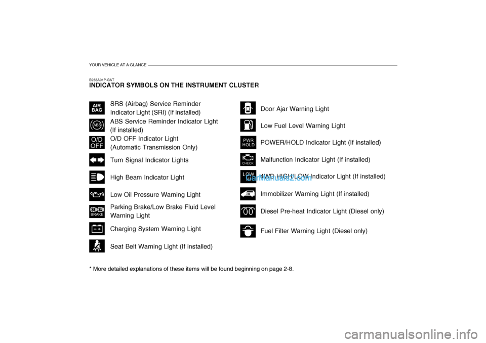
B255A01P-GAT INDICATOR SYMBOLS ON THE INSTRUMENT CLUSTER * More detailed explanations of these items will be found beginning on page 2-8.
O/D OFF Indicator Light (Automatic Transmission Only)
Fuel Filter Warning Light (Diesel only)
Diesel Pre-heat Indicator Light (Diesel only)
Immobilizer Warning Light (If installed)
SRS (Airbag) Service Reminder Indicator Light (SRI) (If installed)
ABS Service Reminder Indicator Light(If installed)
Turn Signal Indicator Lights High Beam Indicator LightLow Oil Pressure Warning Light Parking Brake/Low Brake Fluid Level Warning Light Charging System Warning Light Seat Belt Warning Light (If installed) Door Ajar Warning Light Low Fuel Level Warning Light
POWER/HOLD Indicator Light (If installed) Malfunction Indicator Light (If installed)
4WD HIGH/LOW Indicator Light (If installed)
Page 70 of 284
2
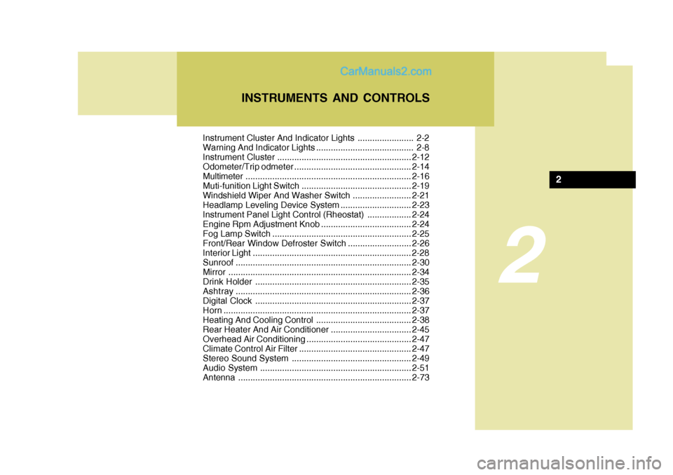
Instrument Cluster And Indicator Lights ....................... 2-2
Warning And Indicator Lights ........................................ 2-8
Instrument Cluster....................................................... 2-12
Odometer/Trip odmeter ................................................ 2-14
Multimeter .................................................................... 2-16
Muti-funition Light Switch ............................................. 2-19
Windshield Wiper And Washer Switch ........................2-21
Headlamp Leveling Device System .............................2-23
Instrument Panel Light Control (Rheostat) ..................2-24
Engine Rpm Adjustment Knob ..................................... 2-24
Fog Lamp Switch ......................................................... 2-25
Front/Rear Window Defroster Switch ..........................2-26
Interior Light ....................... .......................................... 2-28
Sunroof ........................................................................ 2-30
Mirror ........................................................................... 2-34
Drink H older ................................................................ 2-35
Ashtray ........................................................................ 2-36
Digital Clock ................................................................ 2-37
Horn ............................................................................. 2-37
Heating And Cooling Control .......................................2-38
Rear Heater And Air Conditioner ................................. 2-45
Overhead Air C onditioning ........................................... 2-47
Climate Control Air Filter .............................................. 2-47
Stereo Sound System ................................................. 2-49
Audio System .............................................................. 2-51
Antenna ....................................................................... 2-73
INSTRUMENTS AND CONTROLS
2
Page 72 of 284
2
INSTRUMENTS AND CONTROLS
3
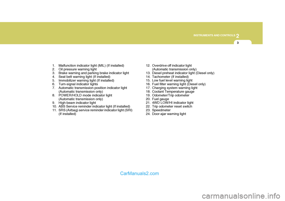
1. Malfunction indicator light (MIL) (If installed)
2. Oil pressure warning light
3. Brake warning and parking brake indicator light
4. Seat belt warning light (If installed)
5. Immobilizer warning light (If installed)
6. Turn-signal indicator lights
7. Automatic transmission position indicator light (Automatic transmission only)
8. POWER/HOLD mode indicator light
(Automatic transmission only)
9. High-beam indicator light
10. ABS Service reminder indicator light (If installed)
11. SRS (Airbag) service reminder indicator light (SRI) (If installed) 12. Overdrive off indicator light
(Automatic transmission only)
13. Diesel preheat indicator light (Diesel only)
14. Tachometer (If installed)
15. Low fuel level warning light
16. Fuel filter warning light (Diesel only)
17. Charging system warning light
18. Coolant Temperature gauge
19. Odometer/Trip odometer
20. Fuel gauge
21. 4WD LOW/Hl indicator light
22. Trip odometer reset switch
23. Speedmeter
24. Door-ajar warning light
Page 74 of 284
2
INSTRUMENTS AND CONTROLS
5
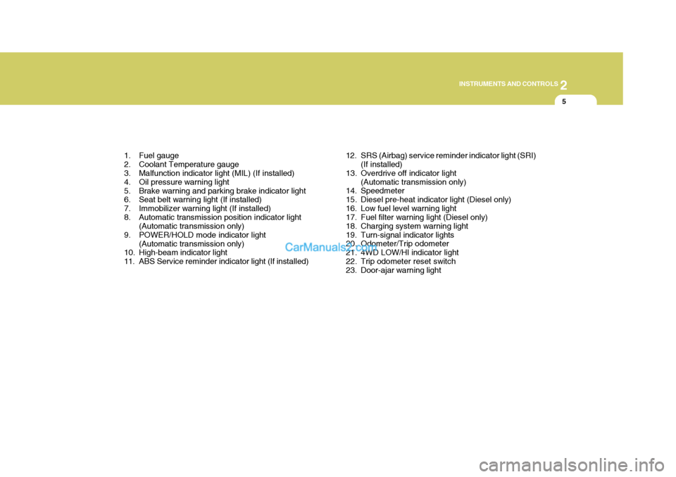
1. Fuel gauge
2. Coolant Temperature gauge
3. Malfunction indicator light (MIL) (If installed)
4. Oil pressure warning light
5. Brake warning and parking brake indicator light
6. Seat belt warning light (If installed)
7. Immobilizer warning light (If installed)
8. Automatic transmission position indicator light (Automatic transmission only)
9. POWER/HOLD mode indicator light
(Automatic transmission only)
10. High-beam indicator light
11. ABS Service reminder indicator light (If installed) 12. SRS (Airbag) service reminder indicator light (SRI)
(If installed)
13. Overdrive off indicator light (Automatic transmission only)
14. Speedmeter
15. Diesel pre-heat indicator light (Diesel only)
16. Low fuel level warning light
17. Fuel filter warning light (Diesel only)
18. Charging system warning light
19. Turn-signal indicator lights
20. Odometer/Trip odometer
21. 4WD LOW/Hl indicator light
22. Trip odometer reset switch
23. Door-ajar warning light
Page 76 of 284
2
INSTRUMENTS AND CONTROLS
7
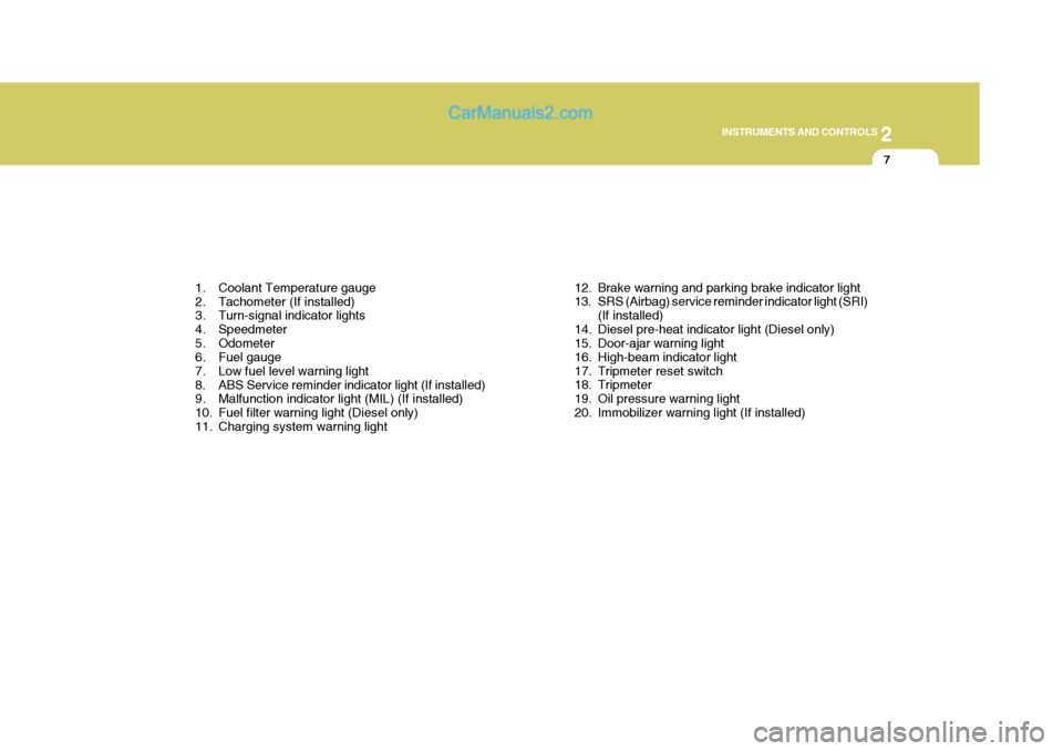
1. Coolant Temperature gauge
2. Tachometer (If installed)
3. Turn-signal indicator lights
4. Speedmeter
5. Odometer
6. Fuel gauge
7. Low fuel level warning light
8. ABS Service reminder indicator light (If installed)
9. Malfunction indicator light (MIL) (If installed)
10. Fuel filter warning light (Diesel only)
11. Charging system warning light 12. Brake warning and parking brake indicator light
13. SRS (Airbag) service reminder indicator light (SRI)
(If installed)
14. Diesel pre-heat indicator light (Diesel only)
15. Door-ajar warning light
16. High-beam indicator light
17. Tripmeter reset switch
18. Tripmeter
19. Oil pressure warning light
20. Immobilizer warning light (If installed)
Page 116 of 284
2
INSTRUMENTS AND CONTROLS
47
Clamp
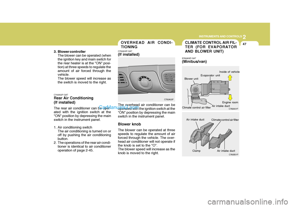
CLIMATE CONTROL AIR FIL- TER (FOR EVAPORATOR AND BLOWER UNIT)
B760A05P-GAT (Minibus/van)
Blower unitOVERHEAD AIR CONDI- TIONING
C750A03P-GAT (If installed) The overhead air conditioner can be operated with the ignition switch at the "ON" position by depressing the mainswitch in the instrument panel. Blower knob The blower can be operated at three speeds to regulate the amount of air forced through the vehicle. The over- head air conditioner will not operate ifthe knob is set to the "O". The blower speed will increase as the knob is moved to the right.
C740A02P-GAT Rear Air Conditioning (If installed) The rear air conditioner can be oper- ated with the ignition switch at the "ON" position by depressing the mainswitch in the instrument panel.
1. Air conditioning switch
The air conditioning is turned on or off by pushing the air conditioning button.
2. The operations of the rear air condi- tioner is identical to air conditioneroperation of page 2-45. C750A03P
C760A01P
C760B01P
Evaporator unit Air intake ductInside of vehicle
Engine room
Air intake duct
Air intake duct
Climate control air filter
Climate control air filter
3. Blower controller
The blower can be operated (when the ignition key and main switch for the rear heater is at the "ON" posi- tion) at three speeds to regulate theamount of air forced through the vehicle. The blower speed will increase asthe switch is moved to the right.
Page 117 of 284
2 INSTRUMENTS AND CONTROLS
48
The climate control air filter is located in the air intake duct behind the wind-shield washer reservoir. It operates to decrease the amount of pollutants entering the car.To replace the climate control air filter, refer to the page 8-16.
CAUTION:
o Replace the filter every 15,000 km (10,000 miles) or once a year. If the car is being driven in severe conditions such as dusty, rough roads, more frequent climate con-trol air filter inspections and changes are required.
o When the air flow rate is sud- denly decreased, it must bechecked at authorized dealer.
!
Page 199 of 284
4
CORROSION PREVENTION AND APPEARANCE CARE
21
4
IN CASE OF EMERGENCY
21BLEEDING THE FUEL SYSTEM
CAUTION:
If overheating should occur when towing, (temperature gauge reads near red zone), taking the followingaction may reduce or eliminate the problem.
1. Turn off the air conditioner.
2. Reduce highway speed.
3. Select a lower gear when going uphill.
4. While in stop and go traffic, place
the gear selection in park or neu-tral and idle the engine at a higher speed.
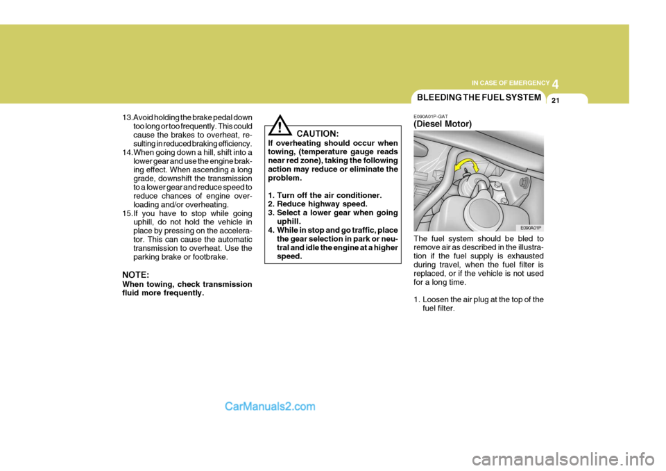
! E090A01P-GAT (Diesel Motor) The fuel system should be bled to remove air as described in the illustra- tion if the fuel supply is exhaustedduring travel, when the fuel filter is replaced, or if the vehicle is not used for a long time.
1. Loosen the air plug at the top of the
fuel filter. E090A01P
13.Avoid holding the brake pedal down
too long or too frequently. This could cause the brakes to overheat, re- sulting in reduced braking efficiency.
14.When going down a hill, shift into a
lower gear and use the engine brak-ing effect. When ascending a long grade, downshift the transmissionto a lower gear and reduce speed to reduce chances of engine over- loading and/or overheating.
15.If you have to stop while going uphill, do not hold the vehicle inplace by pressing on the accelera-tor. This can cause the automatic transmission to overheat. Use the parking brake or footbrake.
NOTE: When towing, check transmission fluid more frequently.
Page 200 of 284
44IN CASE OF EMERGENCY
22
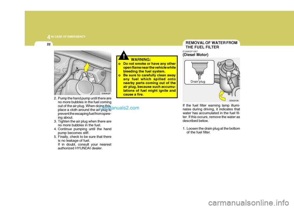
2. Pump the hand pump until there are
no more bubbles in the fuel coming out of the air plug. When doing this,place a cloth around the air plug to prevent the escaping fuel from spew- ing about.
3. Tighten the air plug when there are no more bubbles in the fuel.
4. Continue pumping until the hand pump becomes stiff.
5. Finally, check to be sure that there
is no leakage of fuel.If in doubt, consult your nearest authorized HYUNDAI dealer. E090A02P
REMOVAL OF WATER FROM THE FUEL FILTER
E100A02P-GAT (Diesel Motor) If the fuel filter warning lamp illumi- nates during driving, it indicates that water has accumulated in the fuel fil-ter. If this occurs, remove the water as described below.
1. Loosen the drain plug at the bottom
of the fuel filter. Drain plug
!WARNING:
o Do not smoke or have any other open flame near the vehicle while bleeding the fuel system.
o Be sure to carefully clean away
any fuel which spilled ontonearby parts coming out of the air plug, because such accumu- lations of fuel might ignite andcause a fire.
GS40310A
Page 201 of 284
4
CORROSION PREVENTION AND APPEARANCE CARE
23
4
IN CASE OF EMERGENCY
23IF THE ENGINE WILL NOT START
!WARNING:
o Do not smoke or have any other open flame near the vehicle while bleeding the fuel system.
o Be sure to carefully wipe away
any water drained out in thismanner, because the fuel mixed in the water might be ignited and result in a fire.
NOTE: It is recommended that water accu- mulated in the fuel filter should be removed by an authorized Hyundaidealer.
!
D010A01A-AAT
WARNING:
If the engine will not start, do not push or pull the car to start it. This could result in a collision or causeother damage. In addition, push or pull starting may cause the cata- lytic converter to be overloaded andcreate a fire hazard.
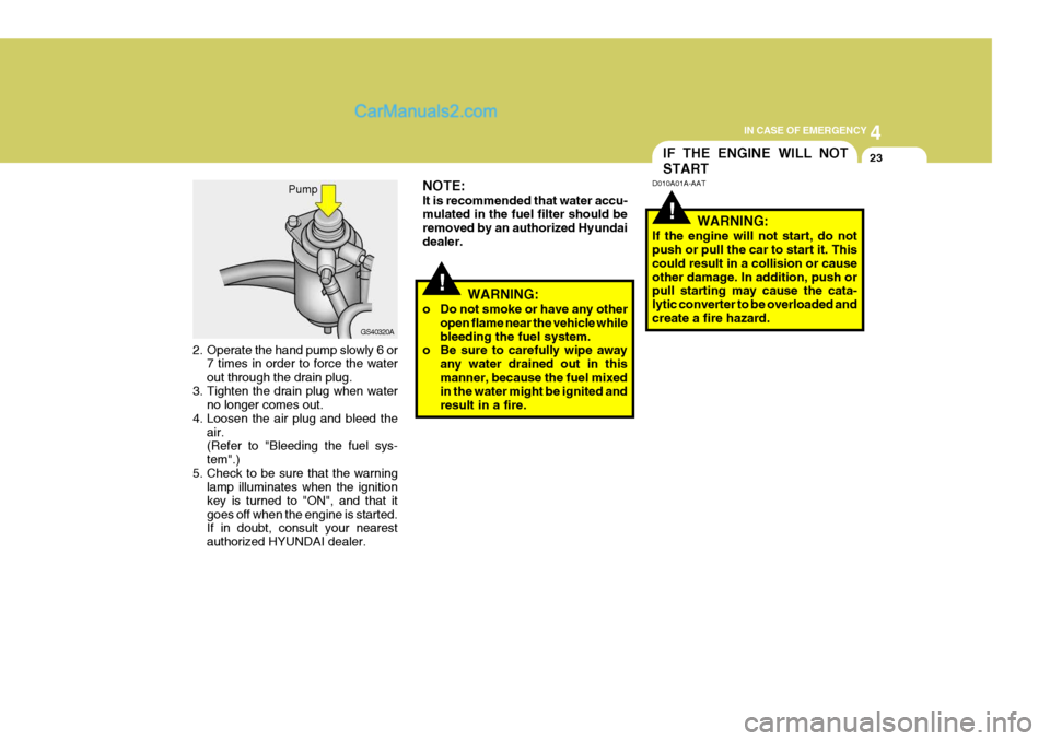
2. Operate the hand pump slowly 6 or 7 times in order to force the waterout through the drain plug.
3. Tighten the drain plug when water no longer comes out.
4. Loosen the air plug and bleed the air. (Refer to "Bleeding the fuel sys- tem".)
5. Check to be sure that the warning lamp illuminates when the ignitionkey is turned to "ON", and that itgoes off when the engine is started. If in doubt, consult your nearest authorized HYUNDAI dealer. Pump
GS40320A