height HYUNDAI I30 2011 User Guide
[x] Cancel search | Manufacturer: HYUNDAI, Model Year: 2011, Model line: I30, Model: HYUNDAI I30 2011Pages: 635, PDF Size: 40.66 MB
Page 134 of 635
Features of your vehicle
56
4
Operation of the rear parking assist system D170101AEN
Operating condition
This system will activate when backing
up with the ignition switch ON.
If the vehicle is moving at a speed over
5 km/h (3 mph), the system may not be
activated correctly.
The sensing distance while the rear parking assist system is in operation is
approximately 120 cm (47 in.).
When more than two objects are sensed at the same time, the closest
one will be recognized first.
D170102AEN
Types of warning sound
When an object is 120 cm to 81 cm (47 in. to 32 in.) from the rear bumper:
Buzzer beeps intermittently.
When an object is 80 cm to 41 cm (31 in. to 16 in.) from the rear bumper:
Buzzer beeps more frequently.
When an object is within 40 cm (15 in.) of the rear bumper:
Buzzer sounds continuously. D170200AEN Non-operational conditions of rear parking assist system
The rear parking assist system may
not operate properly when:
1. Moisture is frozen to the sensor. (It will
operate normally when the moisture has been cleared.)
2. The sensor is covered with foreign matter, such as snow or water, or the
sensor cover is blocked. (It will operate
normally when the material is removed
or the sensor is no longer blocked.)
3. Driving on uneven road surfaces (unpaved roads, gravel, bumps, gradi-ent).
4. Objects generating excessive noise (vehicle horns, loud motorcycle
engines, or truck air brakes) are within
range of the sensor.
5. Heavy rain or water spray exists.
6. Wireless transmitters or mobile phones are within range of the sensor.
7. The sensor is covered with snow.
8. Trailer towing The detecting range may decrease when:
1. The sensor is stained with foreign mat-
ter such as snow or water. (The sens-
ing range will return to normal when
removed.)
2. Outside air temperature is extremely hot or cold.
The following objects may not be rec-
ognized by the sensor:
1. Sharp or slim objects such as ropes, chains or small poles.
2. Objects which tend to absorb the sen- sor frequency such as clothes, spongy
material or snow.
3. Undetectable objects smaller than 1 m (40 in.) in height and narrower than 14
cm (6 in.) in diameter.
Page 135 of 635
457
Features of your vehicle
D170300AEN Rear parking assist system pre- cautions
The rear parking assist system maynot sound sequentially depending on the speed and shapes of the objectsdetected.
The rear parking assist system may malfunction if the vehicle bumperheight or sensor installation has been
modified or damaged. Any non-factory
installed equipment or accessories
may also interfere with the sensor per-
formance.
The sensor may not recognize objects less than 40 cm (15 in.) from the sen-
sor, or it may sense an incorrect dis-
tance. Use caution.
When the sensor is frozen or stained with snow, dirt, or water, the sensor
may be inoperative until the stains are
removed using a soft cloth.
Do not push, scratch or strike the sen- sor. Sensor damage could occur.✽✽ NOTICE
This system can only sense objects with- in the range and location of the sensors;
It can not detect objects in other areas
where sensors are not installed. Also,
small or slim objects, such as poles orobjects located between sensors may notbe detected by the sensors.Always visually check behind the vehi-cle when backing up.
Be sure to inform any drivers of the
vehicle that may be unfamiliar with the
system regarding the systems capabili-ties and limitations.D170400AFD
Self-diagnosis
If you don’t hear an audible warning
sound or if the buzzer sounds intermit-tently when shifting the gear to the R
(Reverse) position, this may indicate a
malfunction in the rear parking assist sys-
tem. If this occurs, have your vehicle
checked by an authorized HYUNDAI
dealer as soon as possible.
WARNING
Pay close attention when the vehi-
cle is driven close to objects on the
road, particularly pedestrians, and
especially children. Be aware that
some objects may not be detected
by the sensors, due to the object’s
distance, size or material, all of
which can limit the effectiveness of
the sensor. Always perform a visu-al inspection to make sure the vehi-
cle is clear of all obstructions
before moving the vehicle in anydirection.
WARNING
Your new vehicle warranty does not
cover any accidents or damage to
the vehicle or injuries to its occu-pants due to a rear parking assist
system malfunction. Always drive
safely and cautiously.
Page 185 of 635
4 107
Features of your vehicle
✽✽NOTICE
If you install an aftermarket HID head
lamp, your vehicle’s audio and electron-ic device may malfunction.
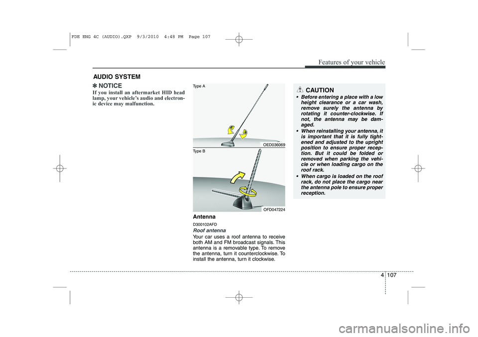
Antenna D300102AFD
Roof antenna
Your car uses a roof antenna to receive
both AM and FM broadcast signals. This
antenna is a removable type. To remove
the antenna, turn it counterclockwise. To
install the antenna, turn it clockwise.
AUDIO SYSTEM
CAUTION
• Before entering a place with a low
height clearance or a car wash,
remove surely the antenna by rotating it counter-clockwise. Ifnot, the antenna may be dam-aged.
When reinstalling your antenna, it is important that it is fully tight-ened and adjusted to the upright position to ensure proper recep-
tion. But it could be folded or removed when parking the vehi-cle or when loading cargo on the roof rack.
When cargo is loaded on the roof rack, do not place the cargo nearthe antenna pole to ensure properreception.
OED036069
OFD047224
Type B Type A
FDE ENG 4C (AUDIO).QXP 9/3/2010 4:48 PM Page 107
Page 263 of 635
Driving your vehicle
20
5
E070300AFD
Anti-lock brake system (ABS) (if equipped) The ABS continuously senses the speed
of the wheels. If the wheels are going to
lock, the ABS system repeatedly modu-
lates the hydraulic brake pressure to the
wheels.
When you apply your brakes under con-
ditions which may lock the wheels, you
may hear a “tik-tik’’ sound from the
brakes, or feel a corresponding sensation
in the brake pedal. This is normal and it
means your ABS is active.
In order to obtain the maximum benefit
from your ABS in an emergency situa-
tion, do not attempt to modulate your
brake pressure and do not try to pump
your brakes. Press your brake pedal as
hard as possible or as hard as the situa-
tion warrants and allow the ABS to con-
trol the force being delivered to the
brakes.
WARNING
ABS (or ESP) will not prevent acci-
dents due to improper or danger-
ous driving maneuvers. Even
though vehicle control is improved
during emergency braking, always
maintain a safe distance between
you and objects ahead. Vehicle
speeds should always be reduced
during extreme road conditions.
The braking distance for cars
equipped with an anti-lock braking
system (Electronic Stability
Program System) may be longer
than for those without it in the fol-
lowing road conditions.
During these conditions the vehicle should be driven at reducedspeeds:
Rough, gravel or snow-covered roads.
With tire chains installed.
On roads where the road surface is pitted or has different surface height.
(Continued)
(Continued)
The safety features of an ABS (or
ESP) equipped vehicle should not
be tested by high speed driving or
cornering. This could endanger the
safety of yourself or others.
Page 365 of 635
Maintenance
48
7
G200601AUN
Compact spare tire replacement (if
equipped)
A compact spare tire has a shorter
tread life than a regular size tire.
Replace it when you can see the
tread wear indicator bars on the tire.The replacement compact spare tire
should be the same size and design
tire as the one provided with your
new vehicle and should be mountedon the same compact spare tire
wheel. The compact spare tire is notdesigned to be mounted on a regular
size wheel, and the compact spare
tire wheel is not designed for mount-
ing a regular size tire. G200700AUN Wheel replacement
When replacing the metal wheels for
any reason, make sure the new
wheels are equivalent to the original
factory units in diameter, rim widthand offset.
(Continued)
The use of any other tire size
or type may seriously affect
ride, handling, ground clear-
ance, stopping distance, body
to tire clearance, snow tire
clearance, and speedometer
reliability.
It is best to replace all four tires at the same time. If that
is not possible, or necessary,
then replace the two front or
two rear tires as a pair.Replacing just one tire can
seriously affect your vehicle’shandling.
The ABS works by comparing the speed of the wheels. Tire
size can affect wheel speed.
When replacing tires, all 4
tires must use the same size
originally supplied with the
vehicle. Using tires of a differ-
ent size can cause the ABS
(Anti-lock Brake System) and
ESP (Electronic Stability
Program) (if equipped) to
work irregularly.
WARNING
A wheel that is not the correct
size may adversely affect wheel
and bearing life, braking and
stopping abilities, handling
characteristics, ground clear-
ance, body-to-tire clearance,
snow chain clearance,speedometer and odometer cal-
ibration, headlight aim and
bumper height.
Page 366 of 635
749
Maintenance
G200800AUN Tire traction
Tire traction can be reduced if you
drive on worn tires, tires that are
improperly inflated or on slippery
road surfaces. Tires should be
replaced when tread wear indicators
appear. To reduce the possibility of
losing control, slow down whenever
there is rain, snow or ice on the road.
G200900AUN Tire maintenance In addition to proper inflation, correct wheel alignment helps to decrease
tire wear. If you find a tire is worn
unevenly, have your dealer check thewheel alignment.
When you have new tires installed,
make sure they are balanced. This
will increase vehicle ride comfort and
tire life. Additionally, a tire should
always be rebalanced if it is removedfrom the wheel.G201000AUN
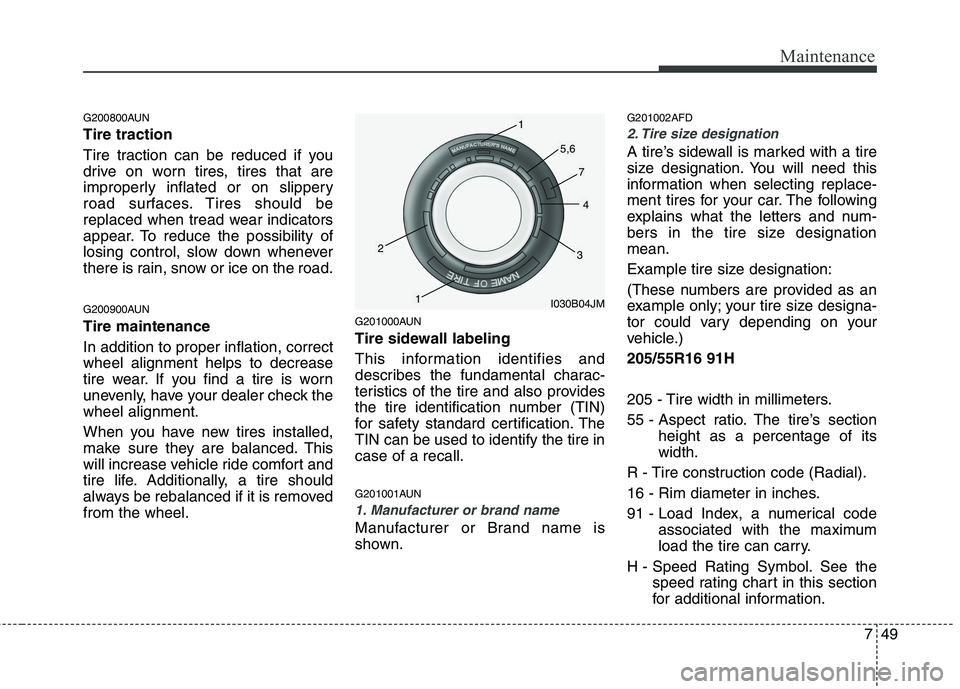
Tire sidewall labeling
This information identifies and
describes the fundamental charac-
teristics of the tire and also provides
the tire identification number (TIN)
for safety standard certification. TheTIN can be used to identify the tire incase of a recall.
G201001AUN
1. Manufacturer or brand name
Manufacturer or Brand name is
shown.G201002AFD
2. Tire size designation
A tire’s sidewall is marked with a tire
size designation. You will need this
information when selecting replace-
ment tires for your car. The following
explains what the letters and num-
bers in the tire size designationmean.
Example tire size designation:
(These numbers are provided as an
example only; your tire size designa-
tor could vary depending on your
vehicle.) 205/55R16 91H
205 - Tire width in millimeters.
55 - Aspect ratio. The tire’s section
height as a percentage of its width.
R - Tire construction code (Radial).
16 - Rim diameter in inches.
91 - Load Index, a numerical code associated with the maximum
load the tire can carry.
H - Speed Rating Symbol. See the speed rating chart in this section
for additional information.
I030B04JM
1
1
23
4
5,6
7
Page 399 of 635
Specifications
2
9
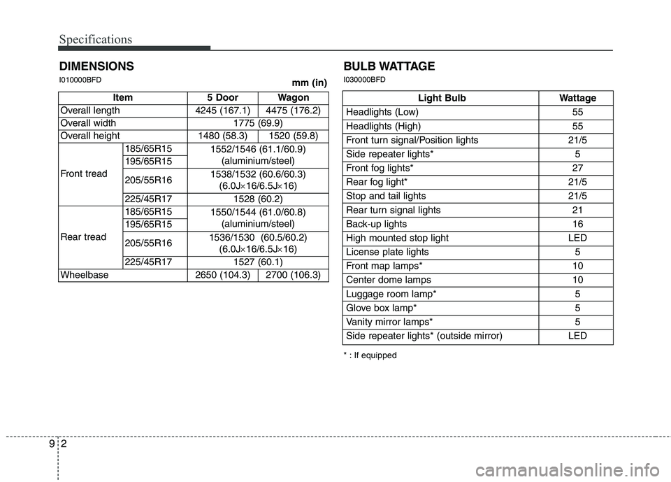
DIMENSIONS I010000BFD
Light Bulb Wattage
Headlights (Low) 55
Headlights (High) 55
Front turn signal/Position lights 21/5
Side repeater lights* 5
Front fog lights* 27
Rear fog light* 21/5
Stop and tail lights 21/5
Rear turn signal lights 21
Back-up lights 16
High mounted stop light LED
License plate lights 5
Front map lamps* 10
Center dome lamps 10
Luggage room lamp* 5
Glove box lamp* 5
Vanity mirror lamps* 5
Side repeater lights* (outside mirror) LED
BULB WATTAGE I030000BFD
* : If equipped
mm (in)
Item 5 Door Wagon
Overall length 4245 (167.1) 4475 (176.2)
Overall width 1775 (69.9)
Overall height 1480 (58.3) 1520 (59.8)
Front tread 185/65R15
1552/1546 (61.1/60.9)
(aluminium/steel)
195/65R15 205/55R16 1538/1532 (60.6/60.3)
(6.0J ×16/6.5J ×16)
225/45R17 1528 (60.2)
Rear tread 185/65R15
1550/1544 (61.0/60.8)
(aluminium/steel)
195/65R15205/55R16 1536/1530 (60.5/60.2)
(6.0J ×16/6.5J ×16)
225/45R17 1527 (60.1)
Wheelbase 2650 (104.3) 2700 (106.3)
Page 415 of 635
Safety system of your vehicle
2
3
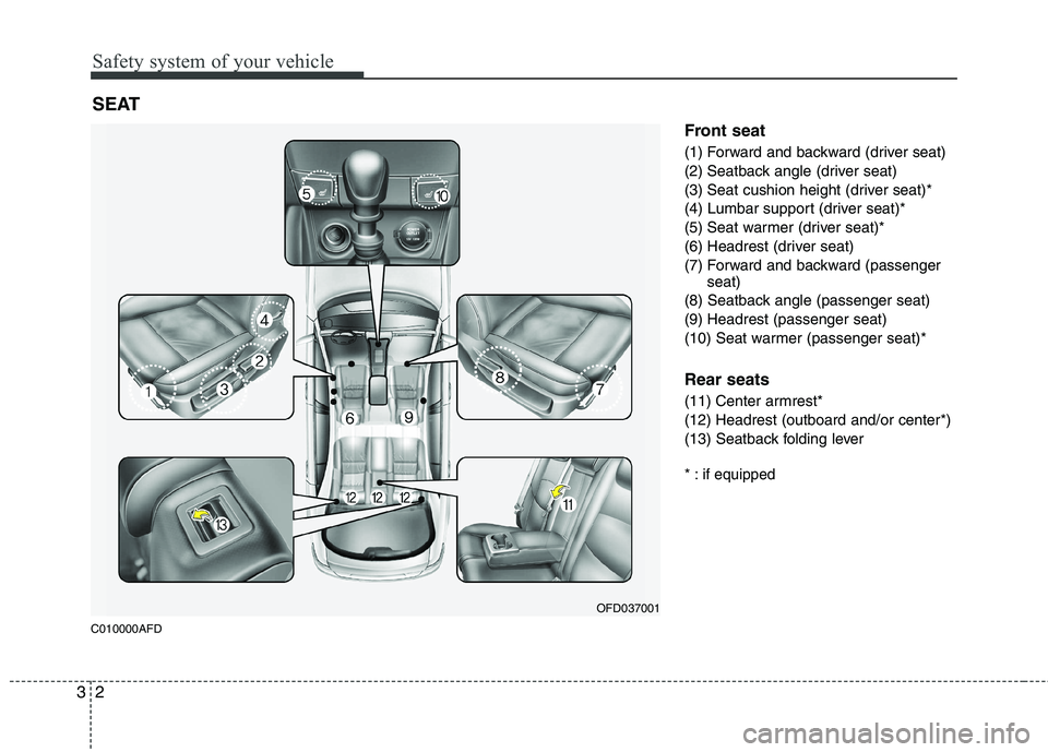
C010000AFD Front seat
(1) Forward and backward (driver seat)
(2) Seatback angle (driver seat)
(3) Seat cushion height (driver seat)*
(4) Lumbar support (driver seat)*
(5) Seat warmer (driver seat)*
(6) Headrest (driver seat)
(7) Forward and backward (passenger
seat)
(8) Seatback angle (passenger seat)
(9) Headrest (passenger seat)
(10) Seat warmer (passenger seat)* Rear seats
(11) Center armrest*
(12) Headrest (outboard and/or center*)
(13) Seatback folding lever
* : if equipped
SEAT
OFD037001
Page 418 of 635
35
Safety system of your vehicle
C010103AUN
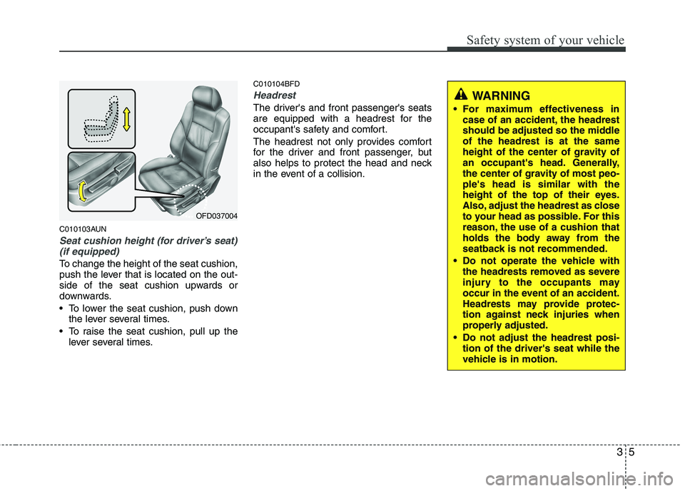
Seat cushion height (for driver’s seat)(if equipped)
To change the height of the seat cushion,
push the lever that is located on the out-
side of the seat cushion upwards or
downwards.
• To lower the seat cushion, push down the lever several times.
To raise the seat cushion, pull up the lever several times. C010104BFD
Headrest
The driver's and front passenger's seats
are equipped with a headrest for the
occupant's safety and comfort.
The headrest not only provides comfort
for the driver and front passenger, but
also helps to protect the head and neck
in the event of a collision.
OFD037004
WARNING
For maximum effectiveness in case of an accident, the headrest
should be adjusted so the middleof the headrest is at the same
height of the center of gravity of
an occupant's head. Generally,
the center of gravity of most peo-ple's head is similar with the
height of the top of their eyes.
Also, adjust the headrest as close
to your head as possible. For this
reason, the use of a cushion that
holds the body away from the
seatback is not recommended.
Do not operate the vehicle with the headrests removed as severe
injury to the occupants may
occur in the event of an accident.
Headrests may provide protec-
tion against neck injuries when
properly adjusted.
Do not adjust the headrest posi- tion of the driver's seat while the
vehicle is in motion.
Page 419 of 635
Safety system of your vehicle
6
3
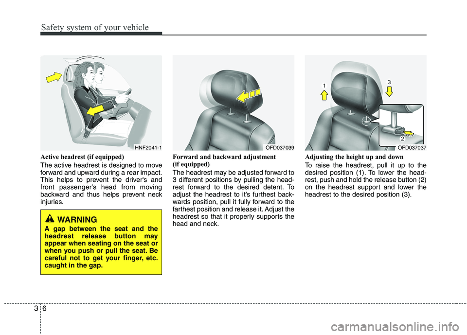
Active headrest (if equipped)
The active headrest is designed to move
forward and upward during a rear impact.
This helps to prevent the driver's and
front passenger’s head from moving
backward and thus helps prevent neck
injuries. Forward and backward adjustment
(if equipped)
The headrest may be adjusted forward to
3 different positions by pulling the head-
rest forward to the desired detent. To
adjust the headrest to it’s furthest back-
wards position, pull it fully forward to the
farthest position and release it. Adjust the
headrest so that it properly supports the
head and neck.Adjusting the height up and down
To raise the headrest, pull it up to the
desired position (1). To lower the head-
rest, push and hold the release button (2)
on the headrest support and lower theheadrest to the desired position (3).
OFD037039OFD037037HNF2041-1
WARNING
A gap between the seat and the
headrest release button mayappear when seating on the seat or
when you push or pull the seat. Be
careful not to get your finger, etc.caught in the gap.