cap HYUNDAI I30 2019 Owner's Manual
[x] Cancel search | Manufacturer: HYUNDAI, Model Year: 2019, Model line: I30, Model: HYUNDAI I30 2019Pages: 659, PDF Size: 17.14 MB
Page 489 of 659
6-19
What to do in an emergency
6
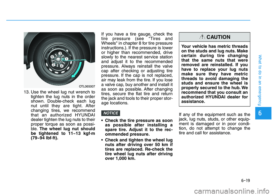
13. Use the wheel lug nut wrench totighten the lug nuts in the order
shown. Double-check each lug
nut until they are tight. After
changing tires, we recommend
that an authorized HYUNDAI
dealer tighten the lug nuts to their
proper torque as soon as possi-
ble. The wheel lug nut should
be tightened to 11~13 kgf·m
(79~94 lbf·ft). If you have a tire gauge, check the
tire pressure (see "Tires and
Wheels" in chapter 8 for tire pressure
instructions.). If the pressure is lower
or higher than recommended, drive
slowly to the nearest service station
and adjust it to the recommended
pressure. Always reinstall the valve
cap after checking or adjusting tire
pressure. If the cap is not replaced,
air may leak from the tire. If you lose
a valve cap, buy another and install it
as soon as possible. After changing
tires, secure the flat tire and return
the jack and tools to their proper stor-
age locations.
Check the tire pressure as soon
as possible after installing a
spare tire. Adjust it to the rec-
ommended pressure.
Check and tighten the wheel lug nuts after driving over 50 km if
tires are replaced. Re-check the
tire wheel lug nuts after driving
over 1,000 km. If any of the equipment such as the
jack, lug nuts, studs, or other equip-
ment is damaged or in poor condi-
tion, do not attempt to change the
tire and call for assistance.
NOTICE
OTL065007
Your vehicle has metric threads
on the studs and lug nuts. Make
certain during tire changing
that the same nuts that were
removed are reinstalled. If you
have to replace your lug nuts
make sure they have metric
threads to avoid damaging the
studs and ensure the wheel is
properly secured to the hub. We
recommend that you consult an
authorized HYUNDAI dealer for
assistance.
CAUTION
Page 490 of 659
6-20
What to do in an emergency
Use of compact spare tires (if equipped)
Compact spare tires are designed for
emergency use only. Drive carefully
on the compact spare tire and
always follow the safety precautions. When driving with the compact spare
tire mounted to your vehicle:
Check the tire pressure after
installing the compact spare tire.
The compact spare tire should be
inflated to 420 kPa (60 psi).
Do not take this vehicle through an automatic car wash while the com-
pact spare tire is installed.
Do not use the compact spare tire on any other vehicle because this
tire has been designed especially
for your vehicle.
The compact spare tire’s tread life is shorter than a regular tire. Inspect
your compact spare tire regularly
and replace worn compact spare
tires with the same size and design,
mounted on the same wheel.
Do not use more than one compact spare tire at a time.
Do not tow a trailer while the com- pact spare tire is installed. When the original tire and wheel
are repaired and reinstalled on the
vehicle, the lug nut torque must be
set correctly. The correct lug nut
tightening torque is 11~13 kgf·m
(79~94 lbf·ft).
NOTICE
To prevent compact spare tire
failure and loss of control pos-
sibly resulting in an accident:
Use the compact spare tire
only in an emergency.
NEVER operate your vehicle
over 80 km/h (50 mph).
Do not exceed the vehicle’s
maximum load rating or the
load carrying capacity shown
on the sidewall of the com-
pact spare tire.
Do not use the compact spare
tire continuously. Repair or
replace the original tire as
soon as possible to avoid fail-
ure of the compact spare tire.
WARNING
Page 495 of 659
6-25
What to do in an emergency
6
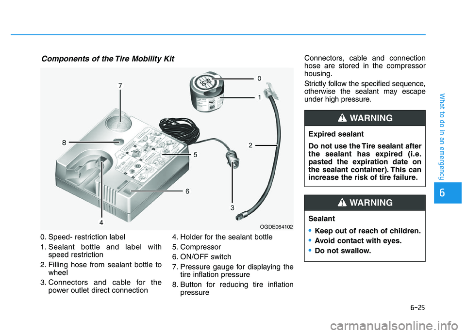
0. Speed- restriction label
1. Sealant bottle and label withspeed restriction
2. Filling hose from sealant bottle to wheel
3. Connectors and cable for the power outlet direct connection 4. Holder for the sealant bottle
5. Compressor
6. ON/OFF switch
7. Pressure gauge for displaying the
tire inflation pressure
8. Button for reducing tire inflation pressure Connectors, cable and connection
hose are stored in the compressor
housing.
Strictly follow the specified sequence,
otherwise the sealant may escape
under high pressure.
Components of the Tire Mobility Kit
OGDE064102
Expired sealant
Do not use the Tire sealant after
the sealant has expired (i.e.
pasted the expiration date on
the sealant container). This can
increase the risk of tire failure.
WARNING
Sealant
Keep out of reach of children.
Avoid contact with eyes.
Do not swallow.
WARNING
Page 497 of 659
6-27
What to do in an emergency
6
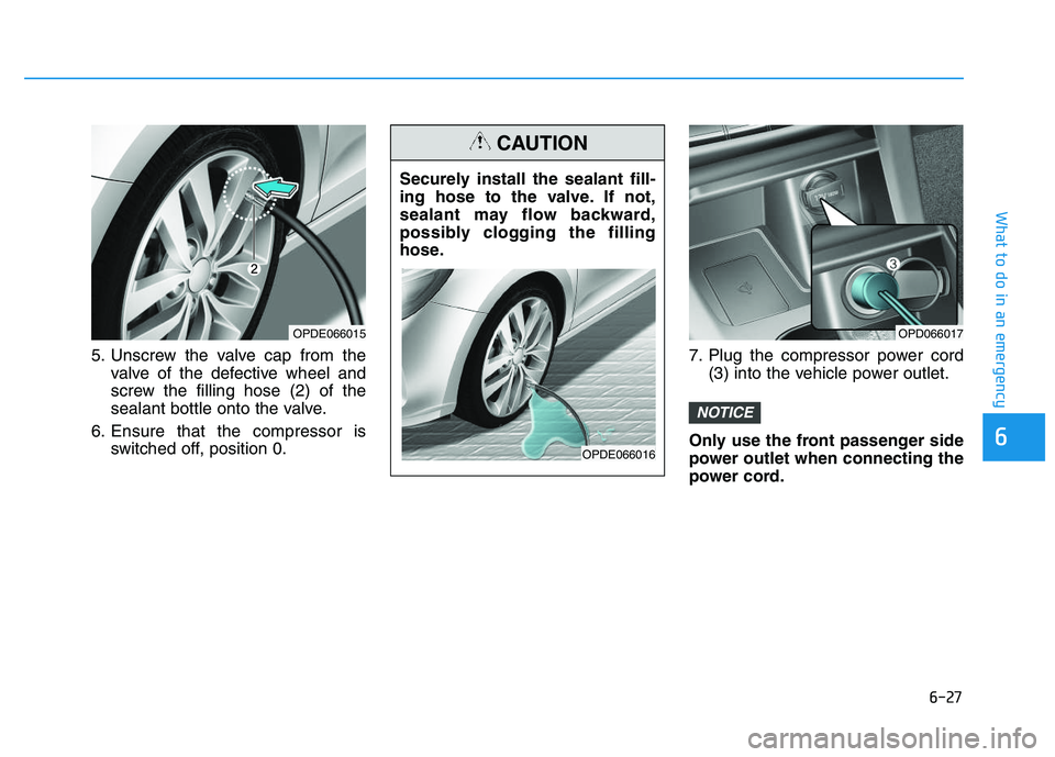
5. Unscrew the valve cap from thevalve of the defective wheel and
screw the filling hose (2) of the
sealant bottle onto the valve.
6. Ensure that the compressor is switched off, position 0. 7. Plug the compressor power cord
(3) into the vehicle power outlet.
Only use the front passenger side
power outlet when connecting the
power cord.
NOTICE
OPD066017OPDE066015
Securely install the sealant fill-
ing hose to the valve. If not,
sealant may flow backward,
possibly clogging the filling
hose.
CAUTION
OPDE066016
Page 503 of 659
6-33
What to do in an emergency
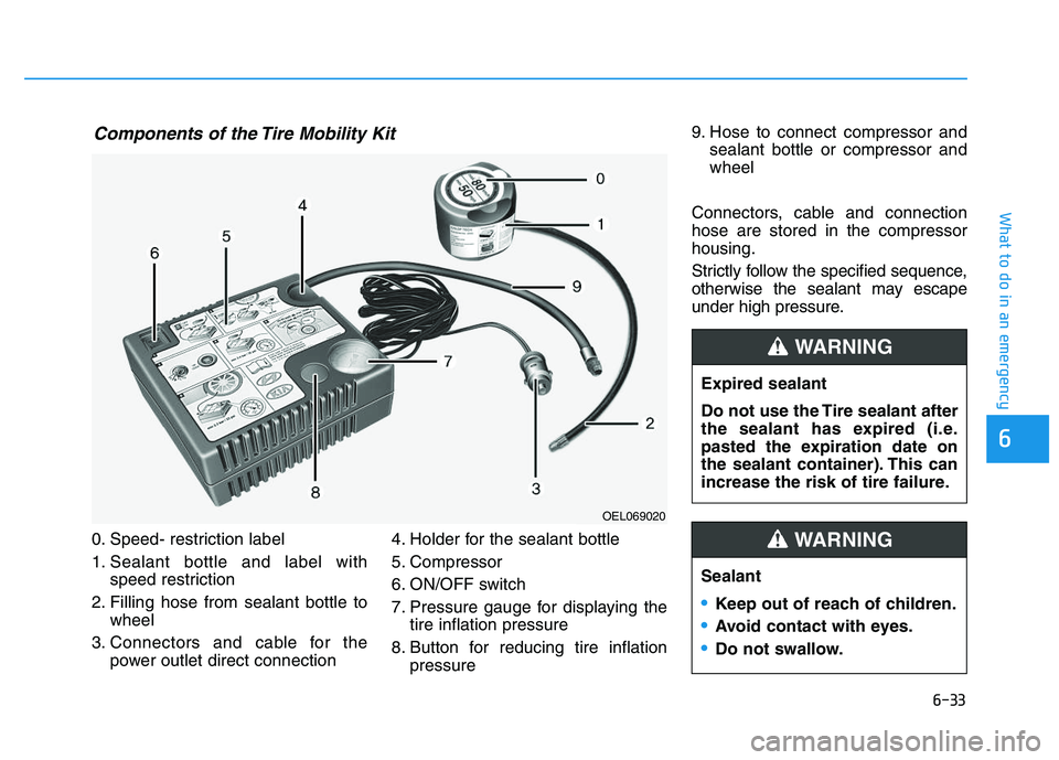
0. Speed- restriction label
1. Sealant bottle and label withspeed restriction
2. Filling hose from sealant bottle to wheel
3. Connectors and cable for the power outlet direct connection 4. Holder for the sealant bottle
5. Compressor
6. ON/OFF switch
7. Pressure gauge for displaying the
tire inflation pressure
8. Button for reducing tire inflation pressure 9. Hose to connect compressor and
sealant bottle or compressor and
wheel
Connectors, cable and connection
hose are stored in the compressor
housing.
Strictly follow the specified sequence,
otherwise the sealant may escape
under high pressure.
6
Components of the Tire Mobility Kit
OEL069020
Expired sealant
Do not use the Tire sealant after
the sealant has expired (i.e.
pasted the expiration date on
the sealant container). This can
increase the risk of tire failure.
WARNING
Sealant
Keep out of reach of children.
Avoid contact with eyes.
Do not swallow.
WARNING
Page 505 of 659
6-35
What to do in an emergency
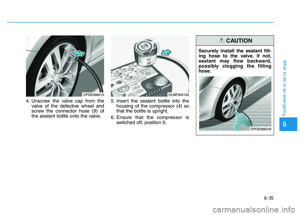
4. Unscrew the valve cap from thevalve of the defective wheel and
screw the connector hose (9) of
the sealant bottle onto the valve. 5. Insert the sealant bottle into the
housing of the compressor (4) so
that the bottle is upright.
6. Ensure that the compressor is switched off, position 0.
6
OLMF064105
Securely install the sealant fill-
ing hose to the valve. If not,
sealant may flow backward,
possibly clogging the filling
hose.
CAUTION
OPDE066016
OPDE066015
Page 513 of 659
6-43
What to do in an emergency
6
Your vehicle is equipped with emer-
gency commodities to help you
respond to emergency situation.
Fire extinguisher
If there is small fire and you know how
to use the fire extinguisher, follow
these steps carefully.
1. Pull out the safety pin at the top ofthe extinguisher that keeps the han-
dle from being accidentally pressed.
2. Aim the nozzle towards the base of the fire.
3. Stand approximately 2.5 m (8 ft) away from the fire and squeeze
the handle to discharge the extin-
guisher. If you release the handle,
the discharge will stop.
4. Sweep the nozzle back and forth at the base of the fire. After the fire
appears to be out, watch carefully
since it may re-ignite.
First aid kit
Supplies for use in giving first aid
such as scissors, bandage and
adhesive tape, etc. are provided.
Triangle reflector
Place the triangle reflector on the
road to warn oncoming vehicles dur-
ing emergencies, such as when the
vehicle is parked by the roadside due
to problems.
Tire pressure gauge
(if equipped)
Tires normally lose some air in day-
to-day use, and you may have to add
a air periodically and usually it is not
a sign of a leaking tire, but of normal
wear. Always check tire pressure
when the tires are cold because tire
pressure increases with temperature. To check the tire pressure, take the
following steps:
1. Unscrew the inflation valve cap
that is located on the rim of the
tire.
2. Press and hold the gauge against the tire valve. Some air will leak as
you begin and more will leak if you
don't press the gauge in firmly.
3. A firm non-leaking push will acti- vate the gauge.
4. Read the tire pressure on the gauge to see whether the tire pressure is
low or high.
5. Adjust the tire pressure to the specified pressure. Refer to “Tires
and Wheels” in chapter 8.
6. Reinstall the inflation valve cap.
E
E M
M E
E R
R G
G E
E N
N C
C Y
Y
C
C O
O M
M M
M O
O D
D I
I T
T Y
Y
(
( I
I F
F
E
E Q
Q U
U I
I P
P P
P E
E D
D )
)
Page 515 of 659
7
Battery...................................................................7-48
For best battery service................................................7-49
Battery capacity label ....................................................7-49
Battery recharging .........................................................7-50
Reset items .......................................................................7-51
Tires and wheels ..................................................7-52
Tire care ............................................................................7-52
Recommended cold tire inflation pressures.............7-53
Check tire inflation pressure........................................7-54
Tire rotation .....................................................................7-54
Wheel alignment and tire balance ..............................7-55
Tire replacement .............................................................7-56
Wheel replacement .........................................................7-57
Tire traction ......................................................................7-57
Tire maintenance ............................................................7-57
Tire sidewall labeling ......................................................7-57
Low aspect ratio tires ....................................................7-61
Fuses ......................................................................7-62
Instrument panel fuse replacement ...........................7-63
Engine compartment panel fuse replacement.........7-64
Fuse/Relay panel description ......................................7-66
Light bulbs.............................................................7-85
Headlamp, static bending lamp,
position lamp, turn signal lamp and
daytime running light bulb replacement ...................7-86Front fog lamp .................................................................7-91
Headlamp and front fog lamp
aiming (for Europe) ........................................................7-91 Side repeater lamp replacement .................................7-97
Rear combination lamp bulb replacement ................7-98
Rear fog lamp ................................................................7-102
High mounted stop lamp replacement .....................7-103
License plate light bulb replacement .......................7-103
Interior light bulb replacement ..................................7-103
Appearance care ................................................7-105
Exterior care ..................................................................7-105
Interior care ...................................................................7-110
Emission control system ...................................7-111
1. Crankcase emission control system ...................7-111
2. Evaporative emission control system ................7-111
3. Exhaust emission control system .......................7-112
Page 516 of 659
7-3
7
Maintenance
E
E N
N G
G I
I N
N E
E
C
C O
O M
M P
P A
A R
R T
T M
M E
E N
N T
T
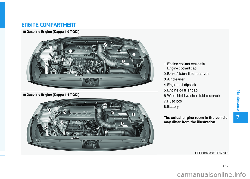
1. Engine coolant reservoir/
Engine coolant cap
2. Brake/clutch fluid reservoir
3. Air cleaner
4. Engine oil dipstick
5. Engine oil filler cap
6. Windshield washer fluid reservoir
7. Fuse box
8. Battery
The actual engine room in the vehicle
may differ from the illustration.
OPDE076088/OPD076001
■
■Gasoline Engine (Kappa 1.0 T-GDI)
■
■Gasoline Engine (Kappa 1.4 T-GDI)
Page 517 of 659
7-4
Maintenance
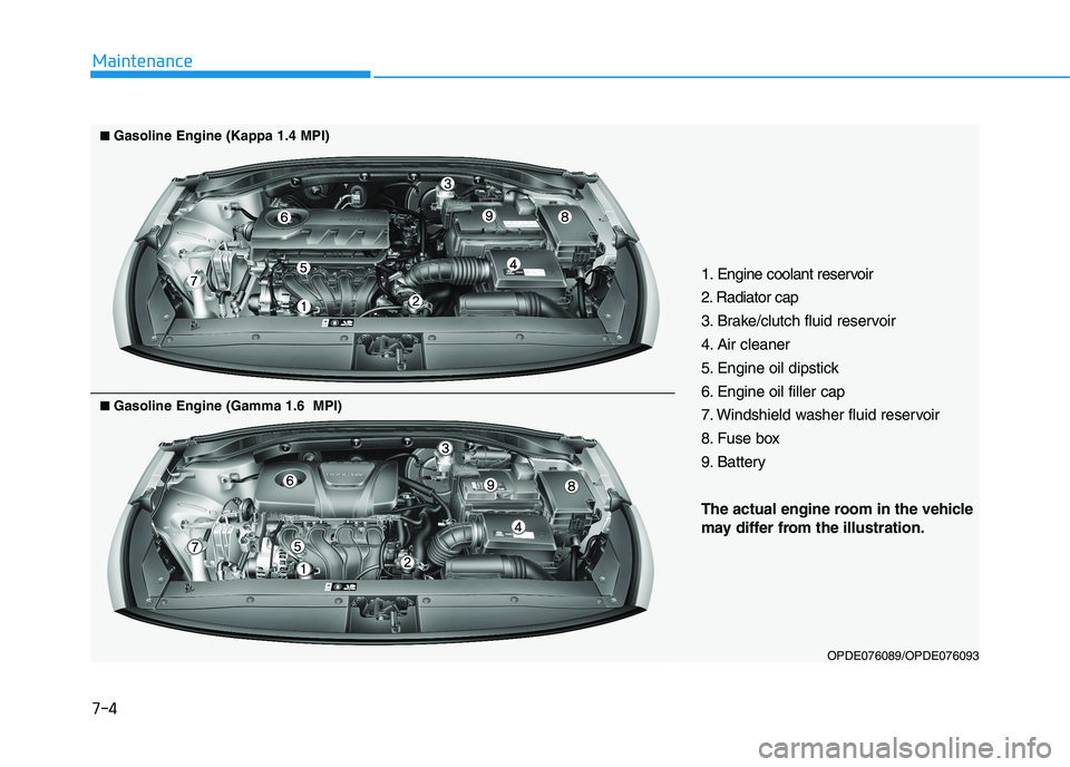
1. Engine coolant reservoir
2. Radiator cap
3. Brake/clutch fluid reservoir
4. Air cleaner
5. Engine oil dipstick
6. Engine oil filler cap
7. Windshield washer fluid reservoir
8. Fuse box
9. Battery
The actual engine room in the vehicle
may differ from the illustration.
OPDE076089/OPDE076093
■
■
Gasoline Engine (Kappa 1.4 MPI)
■
■Gasoline Engine (Gamma 1.6 MPI)