Mount HYUNDAI I40 2012 Owners Manual
[x] Cancel search | Manufacturer: HYUNDAI, Model Year: 2012, Model line: I40, Model: HYUNDAI I40 2012Pages: 534, PDF Size: 11.05 MB
Page 30 of 534
Downloaded from www.Manualslib.com manuals search engine Safety system of your vehicle
63
Automatic adjustment (if equipped)
The front seat can be adjusted by using
the control switches located on the out-
side of the seat cushion. Before driving,
adjust the seat to the proper position so
as to easily control the steering wheel,
pedals and switches on the instrument
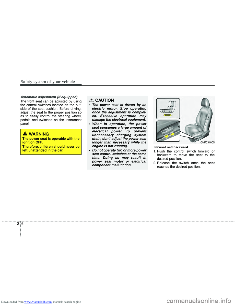
panel.Forward and backward
1. Push the control switch forward orbackward to move the seat to the
desired position.
2. Release the switch once the seat reaches the desired position.
WARNING
The power seat is operable with the
ignition OFF.
Therefore, children should never be
left unattended in the car.
CAUTION
The power seat is driven by an electric motor. Stop operatingonce the adjustment is complet-ed. Excessive operation maydamage the electrical equipment.
When in operation, the power seat consumes a large amount ofelectrical power. To preventunnecessary charging systemdrain, don’t adjust the power seatlonger than necessary while theengine is not running.
Do not operate two or more power seat control switches at the sametime. Doing so may result inpower seat motor or electricalcomponent malfunction.
OVF031005
Page 58 of 534
Downloaded from www.Manualslib.com manuals search engine Safety system of your vehicle
34
3
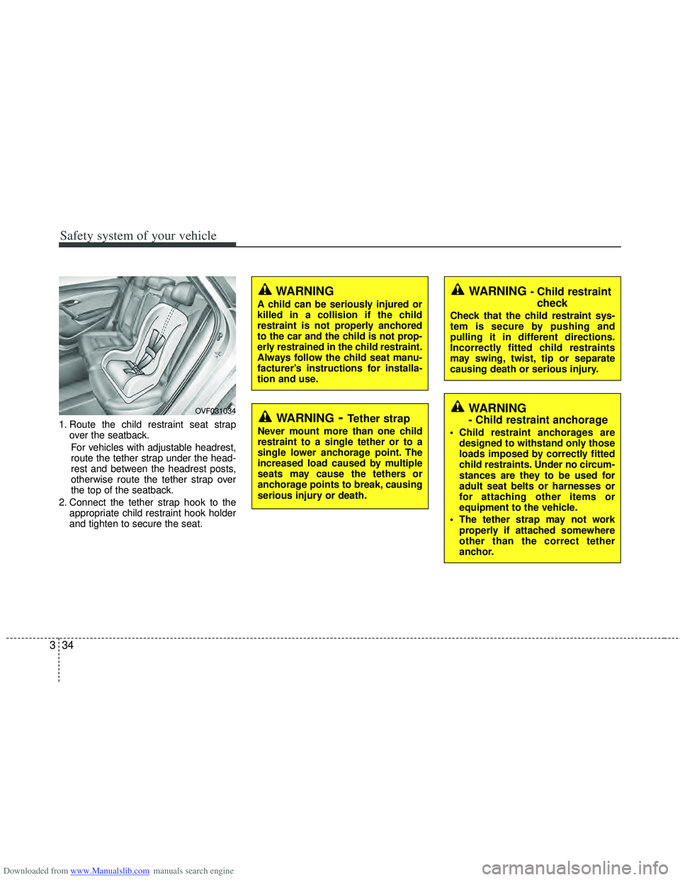
1. Route the child restraint seat strap
over the seatback.
For vehicles with adjustable headrest,
route the tether strap under the head-
rest and between the headrest posts,
otherwise route the tether strap over
the top of the seatback.
2. Connect the tether strap hook to the appropriate child restraint hook holder
and tighten to secure the seat.
OVF031034WARNING- Tether strap
Never mount more than one child
restraint to a single tether or to a
single lower anchorage point. The
increased load caused by multiple
seats may cause the tethers or
anchorage points to break, causing
serious injury or death.
WARNING
A child can be seriously injured or
killed in a collision if the child
restraint is not properly anchored
to the car and the child is not prop-
erly restrained in the child restraint.
Always follow the child seat manu-
facturer’s instructions for installa-
tion and use.
WARNING - Child restraintcheck
Check that the child restraint sys-
tem is secure by pushing and
pulling it in different directions.
Incorrectly fitted child restraints
may swing, twist, tip or separate
causing death or serious injury.
WARNING
- Child restraint anchorage
Child restraint anchorages are
designed to withstand only those
loads imposed by correctly fitted
child restraints. Under no circum-
stances are they to be used for
adult seat belts or harnesses or
for attaching other items or
equipment to the vehicle.
The tether strap may not work properly if attached somewhere
other than the correct tether
anchor.
Page 61 of 534
Downloaded from www.Manualslib.com manuals search engine 337
Safety system of your vehicle
(Continued)
Attach the ISOFIX or ISOFIX-com-patible child restraint seat only to
the appropriate locations shown
in the illustration.
Always follow the installation and use instructions provided by the
manufacturer of the child restraint.WARNING
Do not install a child restraintseat at the center of the rear seat
using the vehicle's ISOFIX
anchors. The ISOFIX anchors are
only provided for the left and
right outboard rear seating posi-
tions. Do not misuse the ISOFIX
anchors by attempting to attach a
child restraint seat in the middle
of the rear seat to the ISOFIX
anchors.
In a crash, the child restraint seat
ISOFIX attachments may not be
strong enough to secure the child
restraint seat properly in the cen-
ter of the rear seat and may
break, causing serious injury or
death.
Do not mount more than one child restraint to a child restraint
lower anchorage point. The
improper increased load may
cause the anchorage points or
tether anchor to break, causing
serious injury or death.
(Continued)
Page 110 of 534
Downloaded from www.Manualslib.com manuals search engine 423
Features of your vehicle
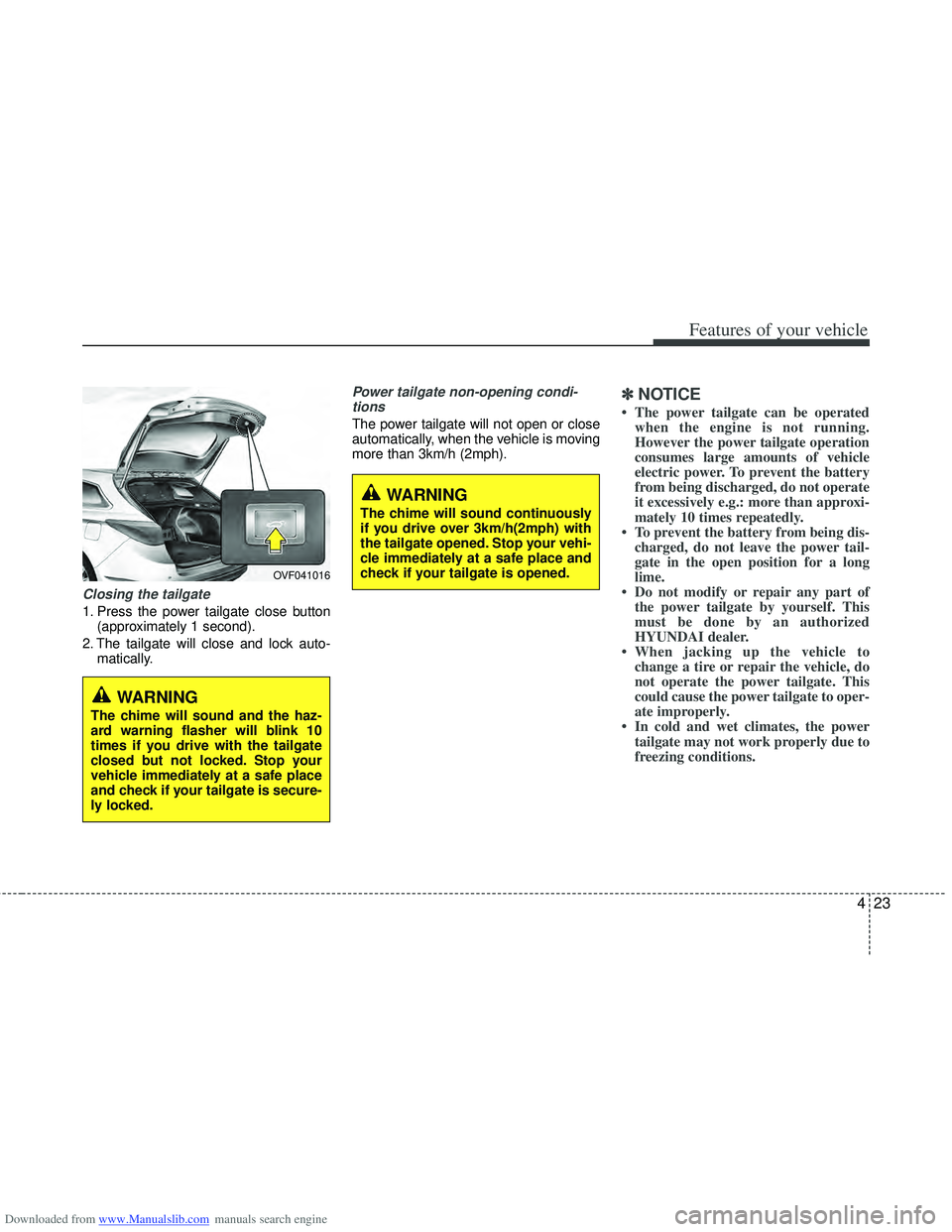
Closing the tailgate
1. Press the power tailgate close button(approximately 1 second).
2. The tailgate will close and lock auto- matically.
Power tailgate non-opening condi-tions
The power tailgate will not open or close
automatically, when the vehicle is moving
more than 3km/h (2mph).
✽ ✽ NOTICE
• The power tailgate can be operated
when the engine is not running.
However the power tailgate operation
consumes large amounts of vehicle
electric power. To prevent the battery
from being discharged, do not operate
it excessively e.g.: more than approxi-
mately 10 times repeatedly.
• To prevent the battery from being dis- charged, do not leave the power tail-
gate in the open position for a long
lime.
• Do not modify or repair any part of the power tailgate by yourself. This
must be done by an authorized
HYUNDAI dealer.
• When jacking up the vehicle to change a tire or repair the vehicle, do
not operate the power tailgate. This
could cause the power tailgate to oper-
ate improperly.
• In cold and wet climates, the power tailgate may not work properly due to
freezing conditions.
OVF041016
WARNING
The chime will sound and the haz-
ard warning flasher will blink 10
times if you drive with the tailgate
closed but not locked. Stop your
vehicle immediately at a safe place
and check if your tailgate is secure-
ly locked.
WARNING
The chime will sound continuously
if you drive over 3km/h(2mph) with
the tailgate opened. Stop your vehi-
cle immediately at a safe place and
check if your tailgate is opened.
Page 131 of 534
Downloaded from www.Manualslib.com manuals search engine Features of your vehicle
44
4
Inside rearview mirror
Adjust the rearview mirror so that the
center view through the rear window is
seen. Make this adjustment before you
start driving.
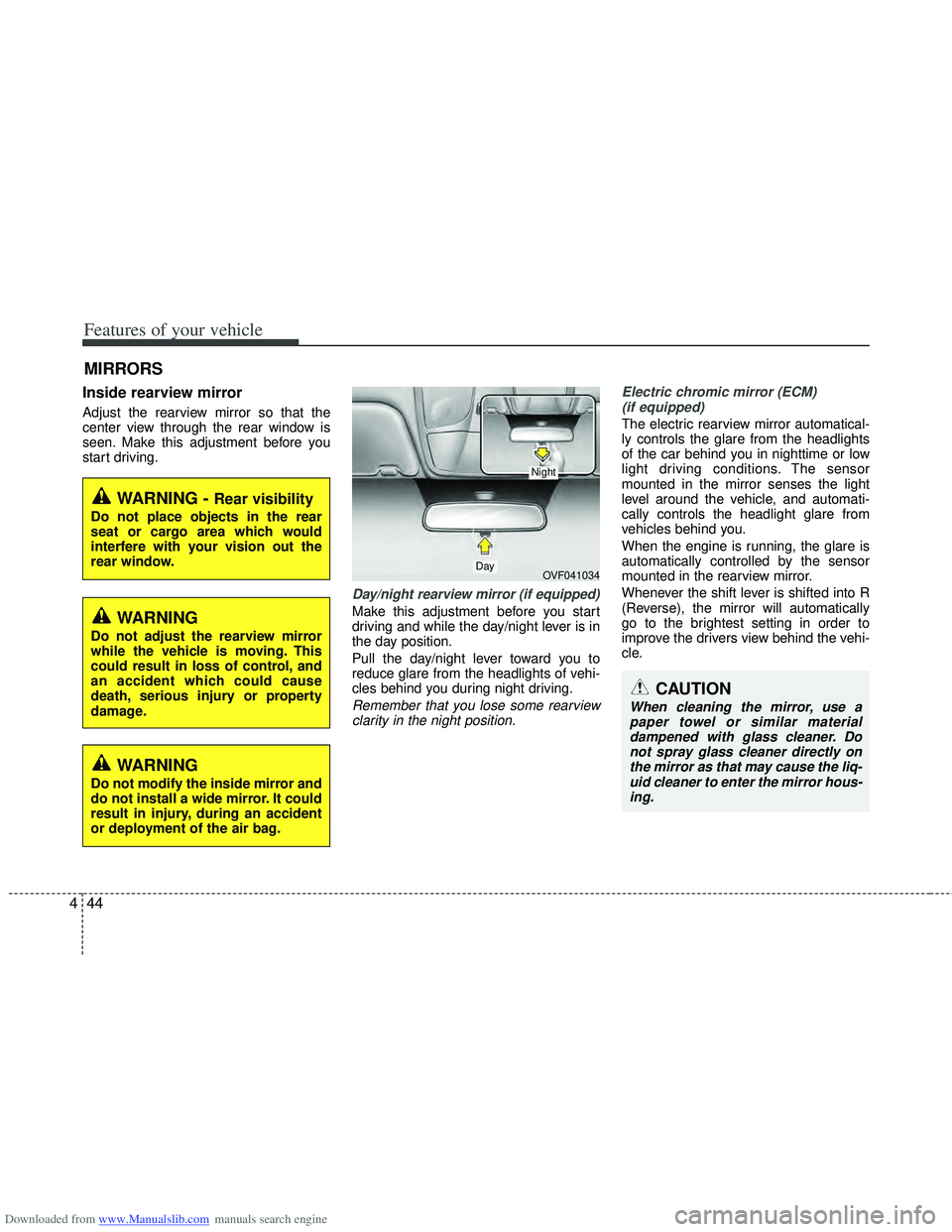
Day/night rearview mirror (if equipped)
Make this adjustment before you start
driving and while the day/night lever is in
the day position.
Pull the day/night lever toward you to
reduce glare from the headlights of vehi-
cles behind you during night driving.
Remember that you lose some rearview
clarity in the night position. Electric chromic mirror (ECM)
(if equipped)
The electric rearview mirror automatical-
ly controls the glare from the headlights
of the car behind you in nighttime or low
light driving conditions. The sensor
mounted in the mirror senses the light
level around the vehicle, and automati-
cally controls the headlight glare from
vehicles behind you.
When the engine is running, the glare is
automatically controlled by the sensor
mounted in the rearview mirror.
Whenever the shift lever is shifted into R
(Reverse), the mirror will automatically
go to the brightest setting in order to
improve the drivers view behind the vehi-
cle.
MIRRORS
WARNING - Rear visibility
Do not place objects in the rear
seat or cargo area which would
interfere with your vision out the
rear window.
OVF041034
CAUTION
When cleaning the mirror, use a paper towel or similar materialdampened with glass cleaner. Donot spray glass cleaner directly onthe mirror as that may cause the liq- uid cleaner to enter the mirror hous-ing.
Day
Night
WARNING
Do not adjust the rearview mirror
while the vehicle is moving. This
could result in loss of control, and
an accident which could cause
death, serious injury or property
damage.
WARNING
Do not modify the inside mirror and
do not install a wide mirror. It could
result in injury, during an accident
or deployment of the air bag.
Page 138 of 534
Downloaded from www.Manualslib.com manuals search engine 451
Features of your vehicle
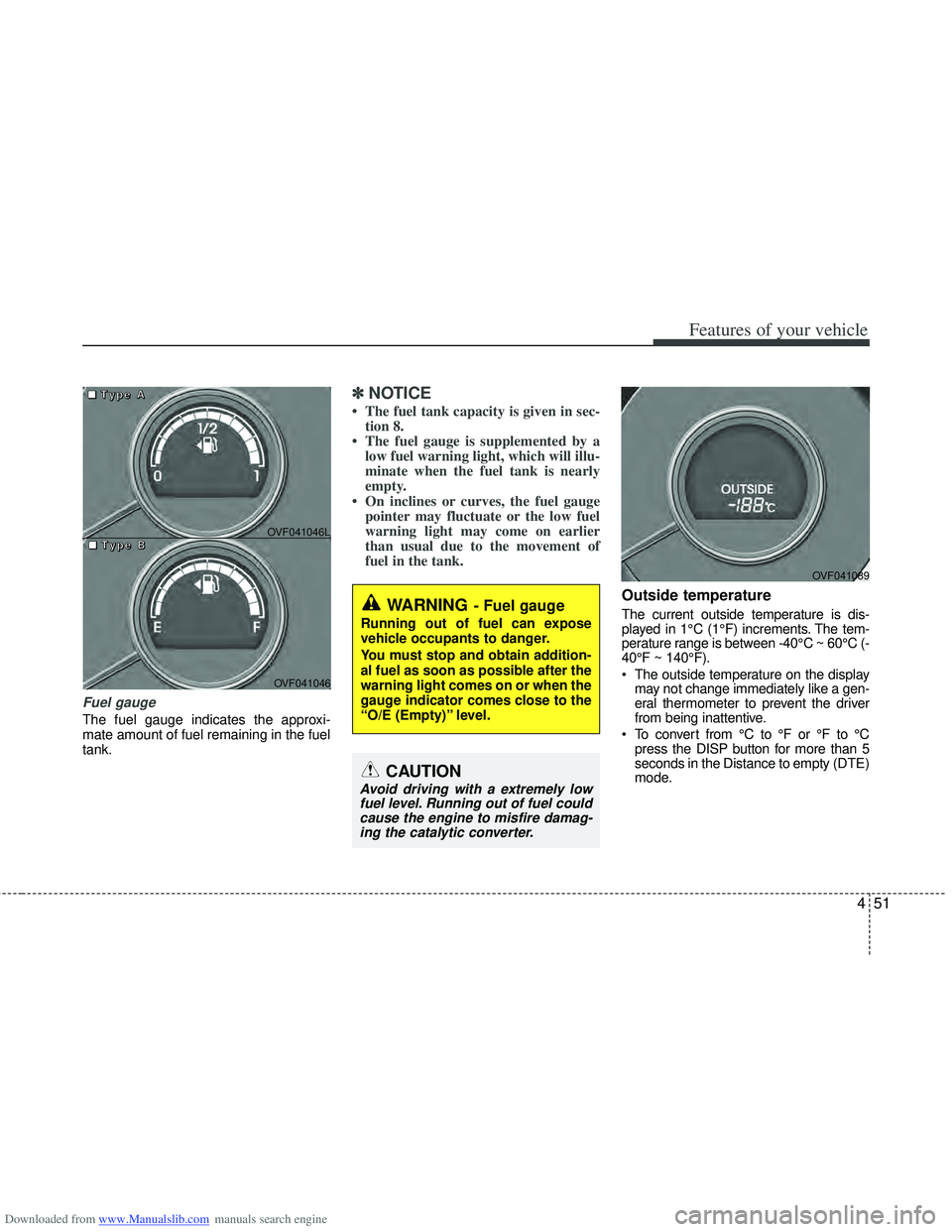
Fuel gauge
The fuel gauge indicates the approxi-
mate amount of fuel remaining in the fuel
tank.
✽ ✽NOTICE
• The fuel tank capacity is given in sec-
tion 8.
• The fuel gauge is supplemented by a low fuel warning light, which will illu-
minate when the fuel tank is nearly
empty.
• On inclines or curves, the fuel gauge pointer may fluctuate or the low fuel
warning light may come on earlier
than usual due to the movement of
fuel in the tank.
Outside temperature
The current outside temperature is dis-
played in 1°C (1°F) increments. The tem-
perature range is between -40°C ~ 60°C (-
40°F ~ 140°F).
The outside temperature on the display
may not change immediately like a gen-
eral thermometer to prevent the driver
from being inattentive.
To convert from °C to °F or °F to °C press the DISP button for more than 5
seconds in the Distance to empty (DTE)
mode.
■
■
■
■
T
T
T
T
y
y
y
y
p
p
p
p
e
e
e
e
A
A
A
A
■
■
■
■
T
T
T
T
y
y
y
y
p
p
p
p
e
e
e
e
B
B
B
B
OVF041046
OVF041046L
WARNING- Fuel gauge
Running out of fuel can expose
vehicle occupants to danger.
You must stop and obtain addition-
al fuel as soon as possible after the
warning light comes on or when the
gauge indicator comes close to the
“O/E (Empty)” level.
CAUTION
Avoid driving with a extremely lowfuel level. Running out of fuel couldcause the engine to misfire damag-ing the catalytic converter.
OVF041089
Page 185 of 534
Downloaded from www.Manualslib.com manuals search engine Features of your vehicle
98
4
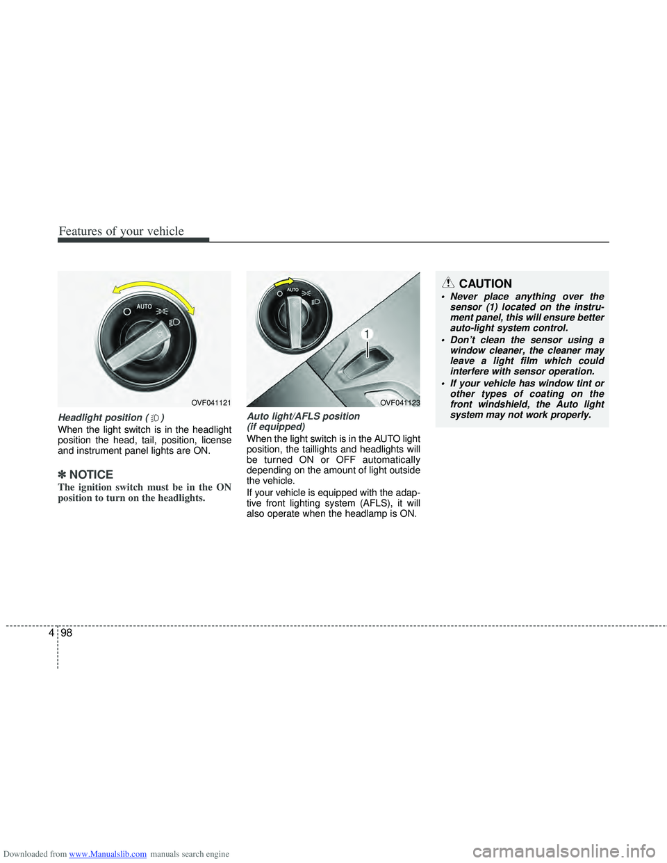
Headlight position ( )
When the light switch is in the headlight
position the head, tail, position, license
and instrument panel lights are ON.
✽ ✽
NOTICE
The ignition switch must be in the ON
position to turn on the headlights.
Auto light/AFLS position
(if equipped)
When the light switch is in the AUTO light
position, the taillights and headlights will
be turned ON or OFF automatically
depending on the amount of light outside
the vehicle.
If your vehicle is equipped with the adap-
tive front lighting system (AFLS), it will
also operate when the headlamp is ON.
OVF041123
CAUTION
Never place anything over the sensor (1) located on the instru-ment panel, this will ensure better auto-light system control.
Don’t clean the sensor using a window cleaner, the cleaner mayleave a light film which could interfere with sensor operation.
If your vehicle has window tint or other types of coating on thefront windshield, the Auto light system may not work properly.
OVF041121
Page 188 of 534
Downloaded from www.Manualslib.com manuals search engine 4101
Features of your vehicle
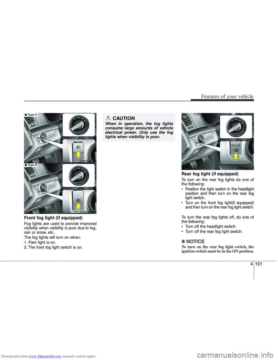
Front fog light (if equipped)
Fog lights are used to provide improved
visibility when visibility is poor due to fog,
rain or snow, etc.
The fog lights will turn on when:
1. Park light is on.
2. The front fog light switch is on.
Rear fog light (if equipped)
To turn on the rear fog lights do one of
the following:
Position the light switch in the headlightposition and then turn on the rear fog
light switch.
Turn on the front fog light(if equipped) and then turn on the rear fog light switch.
To turn the rear fog lights off, do one of
the following:
Turn off the headlight switch.
Turn off the rear fog light switch.
✽ ✽ NOTICE
To turn on the rear fog light switch, the
ignition switch must be in the ON position.
OVF041124
OVF041125
OVF041129
■Type A
■Type B
CAUTION
When in operation, the fog lights consume large amounts of vehicleelectrical power. Only use the foglights when visibility is poor.
Page 192 of 534
Downloaded from www.Manualslib.com manuals search engine 4105
Features of your vehicle
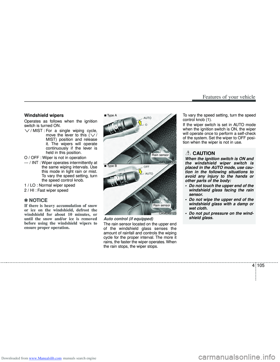
Windshield wipers
Operates as follows when the ignition
switch is turned ON./ MIST : For a single wiping cycle, move the lever to this ( /
MIST) position and release
it. The wipers will operate
continuously if the lever is
held in this position.
O / OFF : Wiper is not in operation
--- / INT : Wiper operates intermittently at the same wiping intervals. Use
this mode in light rain or mist.
To vary the speed setting, turn
the speed control knob.
1 / LO : Normal wiper speed
2 / HI : Fast wiper speed
✽ ✽ NOTICE
If there is heavy accumulation of snow
or ice on the windshield, defrost the
windshield for about 10 minutes, or
until the snow and/or ice is removed
before using the windshield wipers to
ensure proper operation.
Auto control (if equipped)
The rain sensor located on the upper end
of the windshield glass senses the
amount of rainfall and controls the wiping
cycle for the proper interval. The more it
rains, the faster the wiper operates. When
the rain stops, the wiper stops. To vary the speed setting, turn the speed
control knob (1).
If the wiper switch is set in AUTO mode
when the ignition switch is ON, the wiper
will operate once to perform a self-check
of the system. Set the wiper to OFF posi-
tion when the wiper is not in use.
CAUTION
When the ignition switch is ON and
the windshield wiper switch isplaced in the AUTO mode, use cau- tion in the following situations toavoid any injury to the hands orother parts of the body:
Do not touch the upper end of the windshield glass facing the rainsensor.
Do not wipe the upper end of the windshield glass with a damp orwet cloth.
Do not put pressure on the wind- shield glass.OEL049900
OXM049123
■Type A
■Type B
Rain sensor
Rain sensor
Page 201 of 534
Downloaded from www.Manualslib.com manuals search engine Features of your vehicle
114
4
Face-Level (B, D, F)
Air flow is directed toward the upper body
and face. Additionally, each outlet can be
controlled to direct the air discharged
from the outlet.
Bi-Level (B, D, C, E, F)
Air flow is directed towards the face and
the floor.
Floor-Level (A, C, E, D)
Most of the air flow is directed to the
floor, with a small amount of the air being
directed to the windshield and side win-
dow defrosters.
-
Floor/Defrost-Level (A, C, D, E, F)
Most of the air flow is directed to the floor
and the windshield with a small amount
directed to the side window defrosters.
Defrost-Level (A, D)
Most of the air flow is directed to the
windshield with a small amount of air
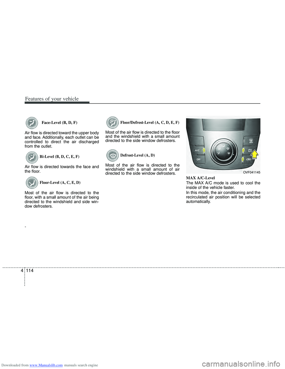
directed to the side window defrosters. MAX A/C-Level
The MAX A/C mode is used to cool the
inside of the vehicle faster.
In this mode, the air conditioning and the
recirculated air position will be selected
automatically.
OVF041145