display HYUNDAI IONIQ 5 2023 Owner's Manual
[x] Cancel search | Manufacturer: HYUNDAI, Model Year: 2023, Model line: IONIQ 5, Model: HYUNDAI IONIQ 5 2023Pages: 680, PDF Size: 48.22 MB
Page 72 of 680
2-2
Vehicle Information, Consumer Information and Reporting Safety DefectsExtErior ovErviEw (i)
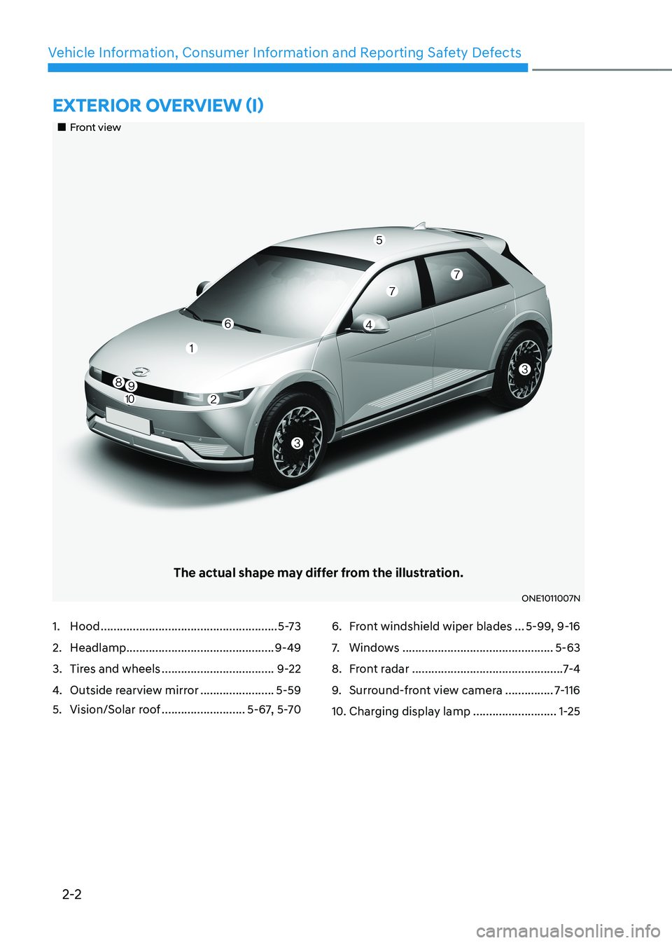
„„Front view
The actual shape may differ from the illustration.
ONE1011007N
1. Hood ....................................................... 5-73
2. Headlamp .............................................. 9-49
3. Tires and wheels ................................... 9-22
4. Outside rearview mirror .......................5-59
5. Vision/Solar roof ..........................5-67, 5-706. Front windshield wiper blades
...5-99, 9-16
7. Windows ............................................... 5-63
8. Front radar ............................................... 7-4
9. Surround-front view camera ...............7-116
10. Charging display lamp ..........................1-25
Page 76 of 680
2-6
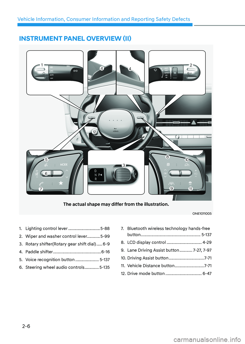
Vehicle Information, Consumer Information and Reporting Safety DefectsinstrumEnt panEl ovErviEw (ii)
The actual shape may differ from the illustration.
ONE1011005
1. Lighting control lever ...........................5-88
2. Wiper and washer control lever........... 5-99
3. Rotary shifter(Rotary gear shift dial) .....6-9
4. Paddle shifter ......................................... 6-16
5. Voice recognition button ....................5-137
6. Steering wheel audio controls ............5-135 7.
Bluetooth wireless technology hands-free
button ................................................... 5-137
8. LCD display control ..............................4-29
9. Lane Driving Assist button ...........7-27, 7-97
10. Driving Assist button ..............................7-7 1
11. Vehicle Distance button .........................7-7 1
12. Drive mode button ...............................6-47
Page 142 of 680
03
3-55
The SRSCM (Supplemental Restraint
System Control Module) continually
monitors all SRS components while the
Start/Stop button is ON to determine if a
crash impact is severe enough to require
air bag deployment or pre-tensioner seat
belt deployment.
SRS warning light
The SRS (Supplemental Restraint System)
air bag warning light on the instrument
panel displays the air bag symbol
depicted in the illustration. The system
checks the air bag electrical system for
malfunctions. The light indicates that
there is a potential problem with your
air bag system, which could include
your side and/or curtain air bags used
for rollover protection (if equipped with
rollover sensor).
WARNING
If your SRS malfunctions, the air bag
may not inflate properly during an
accident increasing the risk of serious
injury or death.
If any of the following conditions occur,
your SRS is malfunctioning: • The light does not turn on for
approximately three to six seconds
when the Start/Stop button is in the ON position.
• The light stays on after illuminating
for approximately three to six
seconds.
• The light comes on while the vehicle
is in motion.
• The light blinks when the vehicle is running.
Have an authorized HYUNDAI dealer inspect the SRS as soon as possible if
any of these conditions occur. During a moderate to severe frontal
collision, sensors will detect the
vehicle’s rapid deceleration. If the rate of
deceleration is high enough, the control
unit will inflate the front air bags, at the
time and with the force needed.
The front air bags help protect the driver
and front passenger by responding to
frontal impacts in which seat belts alone
cannot provide adequate restraint. When
needed, the side air bags help provide
protection in the event of a side impact
or rollover by supporting the side upper
body area. •
Air bags are activated (able to inflate
if necessary) only when the Start/Stop
button is in the ON or START position,
and it can be activated within about 3
minutes after the vehicle is turned off.
• Air bags inflate in the event of certain
frontal or side collisions to help
protect the occupants from serious
physical injury.
• Generally, air bags are designed to
inflate based upon the severity of a
collision, its direction, or etc. These
two factors determine whether
the sensors produce an electronic
deployment/inflation signal.
• The front air bags will completely
inflate and deflate in an instant. It is
virtually impossible for you to see the
air bags inflate during an accident. It is
much more likely that you will simply
see the deflated air bags hanging out
of their storage compartments after the collision.
Page 160 of 680
4
LCD Display Messages ............................................................................................... 4-19
Shift to P ................................................................................................................... 4-19
Low key battery ....................................................................................................... 4-19
Press START button while turning wheel ...............................................................4-19
Press brake pedal to start vehicle .......................................................................... 4-19
Key not in vehicle .................................................................................................... 4-20
Key not detected ...................................................................................................... 4-20
Press START button again ...................................................................................... 4-20
Press START button with key .................................................................................. 4-20
Check BRAKE SWITCH fuse ................................................................................... 4-20
Shift to P or N to start vehicle ................................................................................. 4-20
Check smart key system .......................................................................................... 4-20
Door, Hood, Liftgate open indicator ........................................................................ 4-21
Low tire pressure ...................................................................................................... 4-21
Lights ......................................................................................................................... 4-21
Wiper ........................................................................................................................ 4-22
Low washer fluid ...................................................................................................... 4-22
Check headlight ....................................................................................................... 4-22
Check turn signal ..................................................................................................... 4-22
Check headlamp LED .............................................................................................. 4-22
Shift to P to charge/Shift to P to start charging ....................................................4-23
Remaining time ........................................................................................................ 4-23
Unplug vehicle to start ............................................................................................ 4-23
Charging door open ................................................................................................. 4-23
Charging stopped. Check the AC/DC charger .......................................................4-24
Charging stopped. Check the cable connection ...................................................4-24
Check regenerative brakes...................................................................................... 4-25
Low EV battery ......................................................................................................... 4-25
Charge immediately. Power limited ....................................................................... 4-25
12V battery discharging due to additional electrical devices ..............................4-26
Power limited due to low EV battery temperature. Charge battery .....................4-26
EV battery overheated! Stop vehicle ...................................................................... 4-27
Power limited ........................................................................................................... 4-27
Stop vehicle and check power supply .................................................................... 4-28
Check active air flap system ................................................................................... 4-28
Check virtual engine sound system........................................................................4-28
Check electric vehicle system ................................................................................ 4-28
Page 161 of 680
4
LCD Display ..................................................................................................... 4-29
LCD Display Control ................................................................................................... 4-29
View Modes ................................................................................................................ 4-29
Driving assist view .................................................................................................. 4-30
Turn By Turn (TBT) view .......................................................................................... 4-30
Utility view ................................................................................................................ 4-31
Accumulated info .................................................................................................... 4-31
Additional information display ................................................................................ 4-33
Vehicle Settings (infotainment system) ........................................................4-34
Setting Your Vehicle .................................................................................................. 4-34
4. Instrument Cluster
Page 162 of 680
4-4
Instrument Cluster
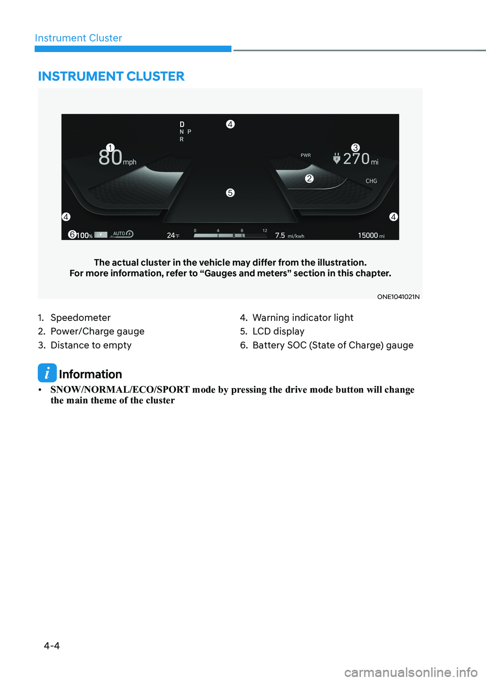
1. Speedometer
2. Power/Charge gauge
3. Distance to empty4.
Warning indicator light
5. LCD display
6. Battery SOC (State of Charge) gauge
Instrument cluster
The actual cluster in the vehicle may differ from the illustration.
For more information, refer to “Gauges and meters” section in this chapter.
ONE1041021N
Information
• SNOW/NORMAL/ECO/SPORT mode by pressing the drive mode button will change the main theme of the cluster
Page 163 of 680
04
4-5
Instrument Cluster Control
Instrument panel illumination
ONE1041055N
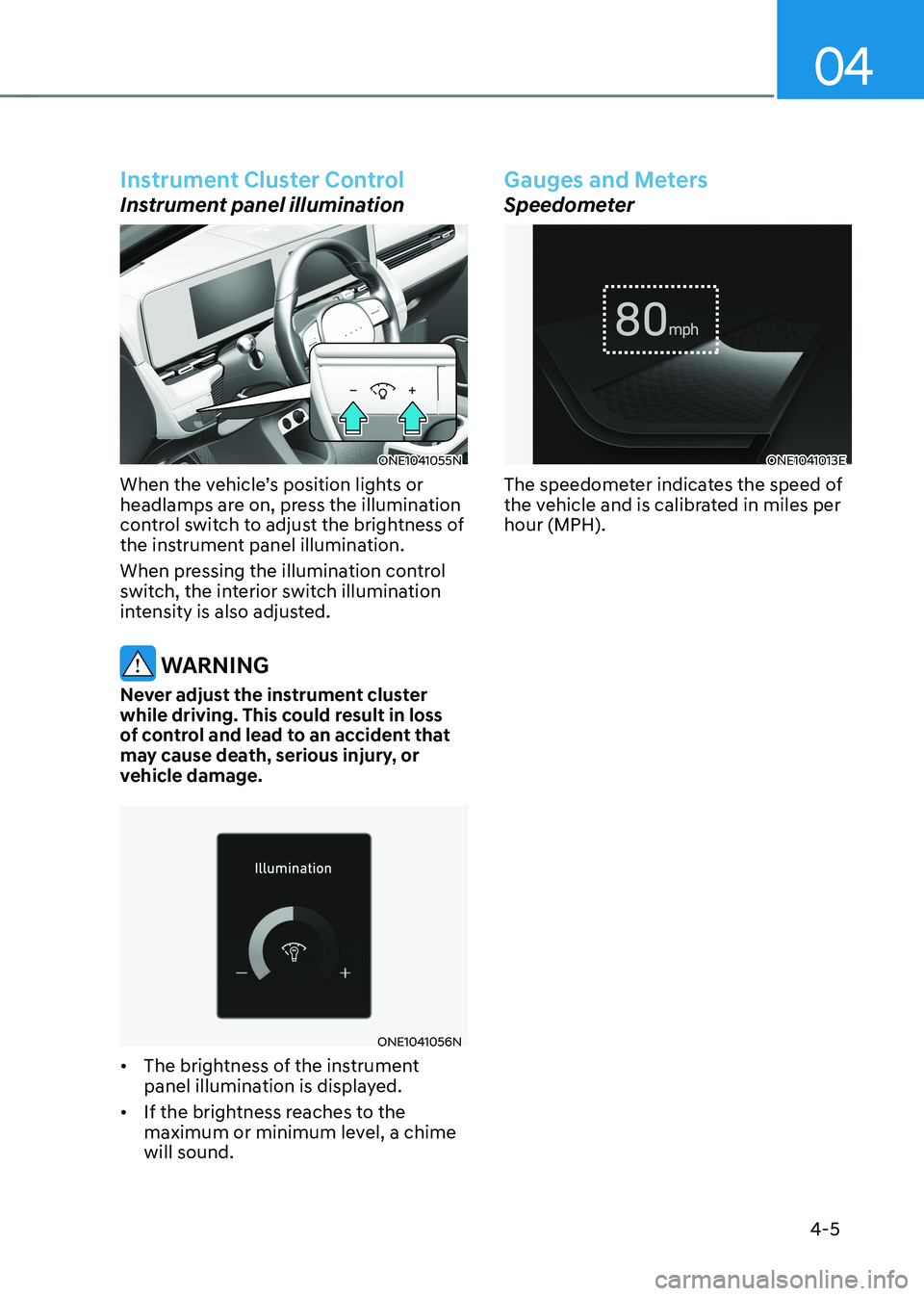
When the vehicle’s position lights or
headlamps are on, press the illumination
control switch to adjust the brightness of
the instrument panel illumination.
When pressing the illumination control
switch, the interior switch illumination
intensity is also adjusted.
WARNING
Never adjust the instrument cluster
while driving. This could result in loss
of control and lead to an accident that
may cause death, serious injury, or
vehicle damage.
ONE1041056N
• The brightness of the instrument
panel illumination is displayed.
• If the brightness reaches to the
maximum or minimum level, a chime will sound.
Gauges and Meters
Speedometer
ONE1041013E
The speedometer indicates the speed of
the vehicle and is calibrated in miles per hour (MPH).
Page 165 of 680
04
4 -7
ONE1Q011011
When the remaining battery is lower than
10 % on the SOC gauge, the warning light (
) turns ON to alert you of the battery
level.
When the warning light (
) turns ON,
the vehicle can drive an additional 18 ~
25 miles (30 ~ 40 km) depending on the
driving speed, heater/air conditioner,
weather, driving style, and other factors.
Charging is required.
NOTICE
The output is limited as the remaining
battery is low.
When the Power Down Indicator Light
is on, the vehicle may be limited to
a certain speed, it may be difficult
to climb hills, or the vehicle may be
pushed back, so charge it immediately. Outside temperature gauge
ONE1041014N
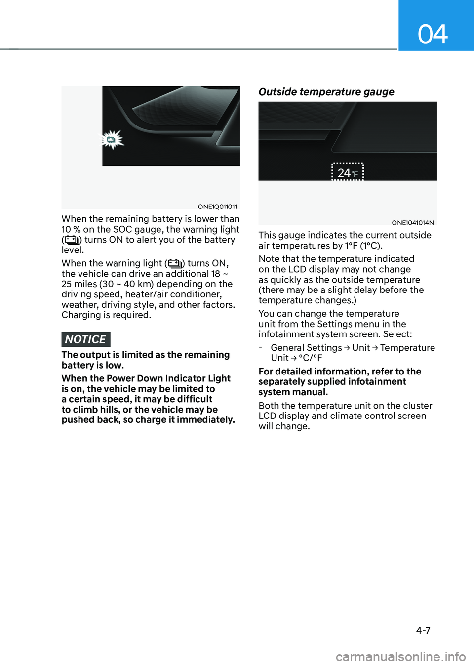
This gauge indicates the current outside
air temperatures by 1°F (1°C).
Note that the temperature indicated
on the LCD display may not change
as quickly as the outside temperature
(there may be a slight delay before the
temperature changes.)
You can change the temperature
unit from the Settings menu in the
infotainment system screen. Select:
- General Settings → Unit → Temperature Unit → °C/°F
For detailed information, refer to the
separately supplied infotainment
system manual.
Both the temperature unit on the cluster
LCD display and climate control screen will change.
Page 167 of 680
04
4-9
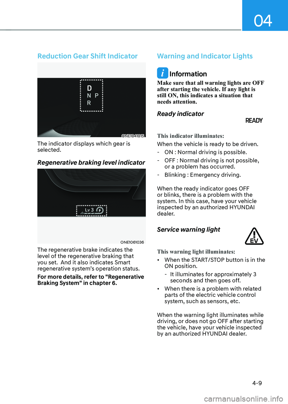
Reduction Gear Shift Indicator
ONE1041015
The indicator displays which gear is
selected.
Regenerative braking level indicator
ONE1061036
The regenerative brake indicates the
level of the regenerative braking that
you set. And it also indicates Smart
regenerative system’s operation status.
For more details, refer to "Regenerative
Braking System" in chapter 6.
Warning and Indicator Lights
Information
Make sure that all warning lights are OFF
after starting the vehicle. If any light is still ON, this indicates a situation that needs attention.
Ready indicator
This indicator illuminates:
When the vehicle is ready to be driven. - ON : Normal driving is possible.
- OFF : Normal driving is not possible, or a problem has occurred.
- Blinking : Emergency driving.
When the ready indicator goes OFF
or blinks, there is a problem with the
system. In this case, have your vehicle
inspected by an authorized HYUNDAI
dealer.
Service warning light
This warning light illuminates:
• When the START/STOP button is in the ON position.
- It illuminates for approximately 3 seconds and then goes off.
• When there is a problem with related
parts of the electric vehicle control
system, such as sensors, etc.
When the warning light illuminates while
driving, or does not go OFF after starting
the vehicle, have your vehicle inspected
by an authorized HYUNDAI dealer.
Page 171 of 680
04
4-13
WARNING
Electronic Brake Force Distribution
(EBD) system warning light
When both ABS and Parking Brake &
Brake Fluid warning lights are on, the
brake system will not work normally
and you may experience an unexpected
and dangerous situation during sudden
braking.
If this occurs, avoid high speed driving
and abrupt braking.
Have the vehicle inspected by an
authorized HYUNDAI dealer as soon as possible.
NOTICE
Electronic Brake Force Distribution
(EBD) system warning light
When the ABS warning light is on
or both ABS and Parking Brake &
Brake Fluid warning lights are on, the
speedometer, odometer, or tripmeter
may not work. Also, the EPS warning
light may illuminate and the steering
effort may increase or decrease.
If this occurs, have the vehicle
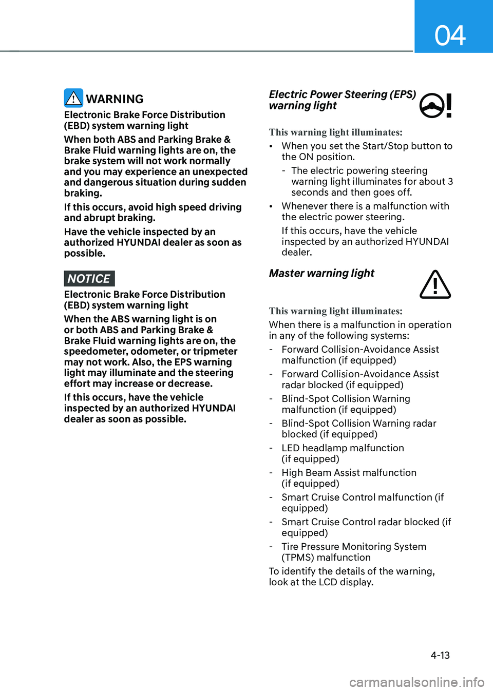
inspected by an authorized HYUNDAI dealer as soon as possible. Electric Power Steering (EPS)
warning light
This warning light illuminates:
•
When you set the Start/Stop button to the ON position.
- The electric powering steering warning light illuminates for about 3
seconds and then goes off.
• Whenever there is a malfunction with
the electric power steering.
If this occurs, have the vehicle
inspected by an authorized HYUNDAI
dealer.
Master warning light
This warning light illuminates:
When there is a malfunction in operation
in any of the following systems: - Forward Collision-Avoidance Assist malfunction (if equipped)
- Forward Collision-Avoidance Assist radar blocked (if equipped)
- Blind-Spot Collision Warning malfunction (if equipped)
- Blind-Spot Collision Warning radar blocked (if equipped)
- LED headlamp malfunction (if equipped)
- High Beam Assist malfunction (if equipped)
- Smart Cruise Control malfunction (if equipped)
- Smart Cruise Control radar blocked (if equipped)
- Tire Pressure Monitoring System (TPMS) malfunction
To identify the details of the warning,
look at the LCD display.