change time HYUNDAI IX35 2016 Owners Manual
[x] Cancel search | Manufacturer: HYUNDAI, Model Year: 2016, Model line: IX35, Model: HYUNDAI IX35 2016Pages: 550, PDF Size: 11.23 MB
Page 24 of 550
35
Safety features of your vehicle
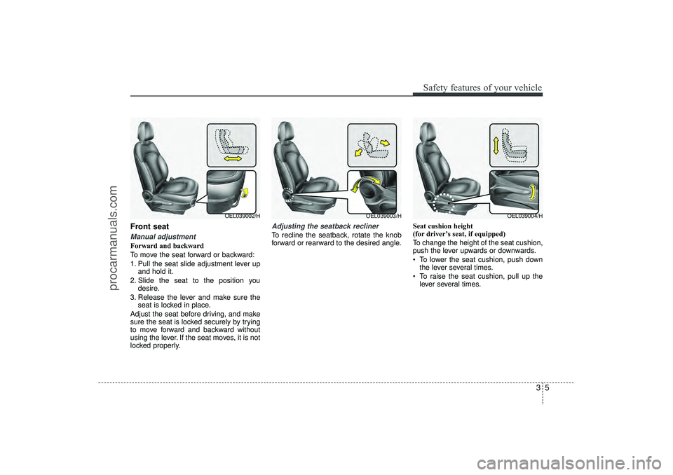
Front seat Manual adjustment Forward and backward
To move the seat forward or backward:
1. Pull the seat slide adjustment lever upand hold it.
2. Slide the seat to the position you desire.
3. Release the lever and make sure the seat is locked in place.
Adjust the seat before driving, and make
sure the seat is locked securely by trying
to move forward and backward without
using the lever. If the seat moves, it is not
locked properly.
Adjusting the seatback reclinerTo recline the seatback, rotate the knob
forward or rearward to the desired angle. Seat cushion height
(for driver’s seat, if equipped)
To change the height of the seat cushion,
push the lever upwards or downwards.
To lower the seat cushion, push down
the lever several times.
To raise the seat cushion, pull up the lever several times.
OEL039003/H
OEL039004/H
OEL039002/H
EL(FL) UK 3.QXP 12/16/2014 8:54 PM Page 5
procarmanuals.com
Page 87 of 550
4
LCD display . . . . . . . . . . . . . . . . . . . . . . . . . . . . . . 4-54• LCD Modes . . . . . . . . . . . . . . . . . . . . . . . . . . . . . . . . . 4-54
• Information Mode . . . . . . . . . . . . . . . . . . . . . . . . . . . . 4-55
• User Settings Mode . . . . . . . . . . . . . . . . . . . . . . . . . . . 4-56
• Warning Messages . . . . . . . . . . . . . . . . . . . . . . . . . . . 4-58Trip computer . . . . . . . . . . . . . . . . . . . . . . . . . . . . . 4-64• Overview . . . . . . . . . . . . . . . . . . . . . . . . . . . . . . . . . . . 4-\
64
• Trip Modes . . . . . . . . . . . . . . . . . . . . . . . . . . . . . . . . . . 4-64\
• Trip A/B . . . . . . . . . . . . . . . . . . . . . . . . . . . . . . . . . . . . \
4-65
• Fuel Economy . . . . . . . . . . . . . . . . . . . . . . . . . . . . . . . 4-66
• Warnings and indicators. . . . . . . . . . . . . . . . . . . . . . . 4-68
• Indicator Lights . . . . . . . . . . . . . . . . . . . . . . . . . . . . . . 4-77Parking assist system . . . . . . . . . . . . . . . . . . . . . . 4-81• Rear parking assist system type . . . . . . . . . . . . . . . . 4-81
• Front/Rear parking assist system type . . . . . . . . . . . 4-85Smart parking assist system . . . . . . . . . . . . . . . . 4-87• Operating condition . . . . . . . . . . . . . . . . . . . . . . . . . . 4-88
• Non-operational conditions . . . . . . . . . . . . . . . . . . . . 4-88
• Operation way . . . . . . . . . . . . . . . . . . . . . . . . . . . . . . . 4-91
• System cancellation whilst parking . . . . . . . . . . . . . . 4-95
• Additional introductions . . . . . . . . . . . . . . . . . . . . . . . 4-96
• System malfunction warning . . . . . . . . . . . . . . . . . . . 4-97Rearview camera . . . . . . . . . . . . . . . . . . . . . . . . . . 4-98Hazard warning flasher . . . . . . . . . . . . . . . . . . . . . 4-98
Lighting . . . . . . . . . . . . . . . . . . . . . . . . . . . . . . . . . 4-99
• Battery saver function . . . . . . . . . . . . . . . . . . . . . . . 4-99
• Headlight escort function . . . . . . . . . . . . . . . . . . . . . 4-99
• Headlight welcome function . . . . . . . . . . . . . . . . . . . 4-99
• Lighting control . . . . . . . . . . . . . . . . . . . . . . . . . . . . . 4-100
• High - beam operation . . . . . . . . . . . . . . . . . . . . . . . 4-101
• Turn signals and lane change signals . . . . . . . . . . . 4-102
• Front fog light . . . . . . . . . . . . . . . . . . . . . . . . . . . . . 4-103
• Rear fog light . . . . . . . . . . . . . . . . . . . . . . . . . . . . . . 4-103
• Daytime running light . . . . . . . . . . . . . . . . . . . . . . . 4-104
• Headlight levelling device . . . . . . . . . . . . . . . . . . . . 4-104Wipers and washers . . . . . . . . . . . . . . . . . . . . . . . 4-106• Windscreen wipers . . . . . . . . . . . . . . . . . . . . . . . . . . 4-107
• Windscreen washers . . . . . . . . . . . . . . . . . . . . . . . . 4-108
• Rear window wiper and washer switch . . . . . . . . . 4-109Interior light . . . . . . . . . . . . . . . . . . . . . . . . . . . . . 4-110• Map lamp . . . . . . . . . . . . . . . . . . . . . . . . . . . . . . . . . 4-110
• Room lamp . . . . . . . . . . . . . . . . . . . . . . . . . . . . . . . . 4-111
• Vanity mirror lamp . . . . . . . . . . . . . . . . . . . . . . . . . . 4-111
• Luggage room lamp . . . . . . . . . . . . . . . . . . . . . . . . . 4-111
• Glove box lamp . . . . . . . . . . . . . . . . . . . . . . . . . . . . . 4-112Defroster . . . . . . . . . . . . . . . . . . . . . . . . . . . . . . . . 4-113• Rear window defroster . . . . . . . . . . . . . . . . . . . . . . . 4-113
EL(FL) UK 4A.QXP 2/9/2015 9:02 PM Page 2
procarmanuals.com
Page 136 of 550
451
Features of your vehicle
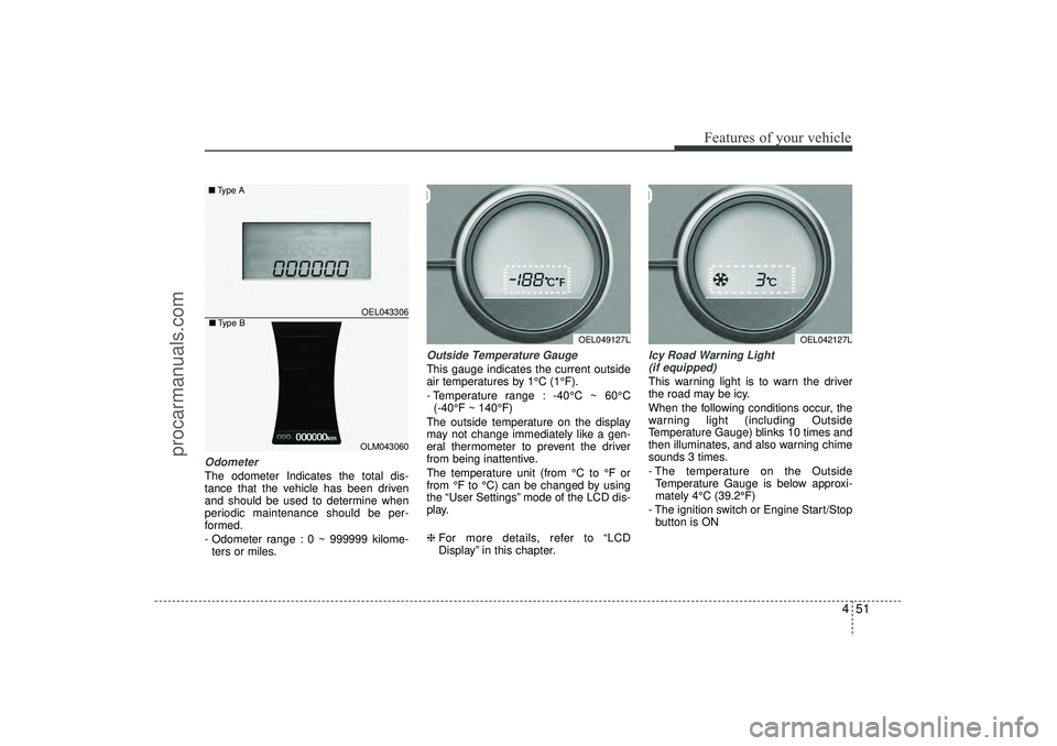
OdometerThe odometer Indicates the total dis-
tance that the vehicle has been driven
and should be used to determine when
periodic maintenance should be per-
formed.
- Odometer range : 0 ~ 999999 kilome-ters or miles.
Outside Temperature GaugeThis gauge indicates the current outside
air temperatures by 1°C (1°F).
- Temperature range : -40°C ~ 60°C (-40°F ~ 140°F)
The outside temperature on the display
may not change immediately like a gen-
eral thermometer to prevent the driver
from being inattentive.
The temperature unit (from °C to °F or
from °F to °C) can be changed by using
the “User Settings” mode of the LCD dis-
play.
❈ For more details, refer to “LCD
Display” in this chapter.
Icy Road Warning Light
(if equipped)This warning light is to warn the driver
the road may be icy.
When the following conditions occur, the
warning light (including Outside
Temperature Gauge) blinks 10 times and
then illuminates, and also warning chime
sounds 3 times.
- The temperature on the Outside Temperature Gauge is below approxi-
mately 4°C (39.2°F)
- The ignition switch or Engine Start/Stop button is ON
OEL049127L
OEL043306
■ Type A
OEL042127L
OLM043060
■Type B
EL(FL) UK 4A.QXP 2/9/2015 9:04 PM Page 51
procarmanuals.com
Page 140 of 550
455
Features of your vehicle
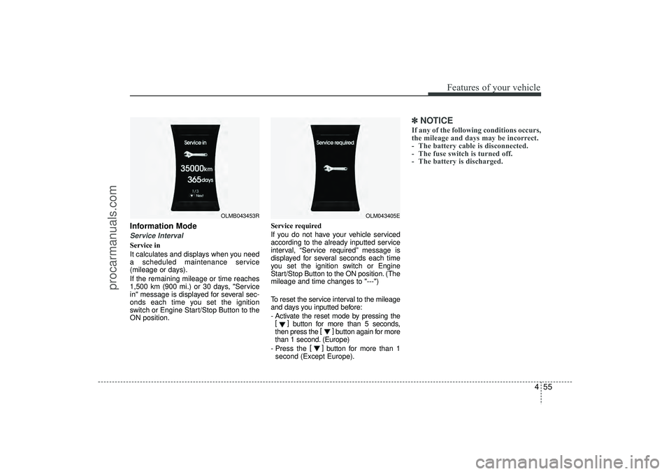
Information ModeService IntervalService in
It calculates and displays when you need
a scheduled maintenance service
(mileage or days).
If the remaining mileage or time reaches
1,500 km (900 mi.) or 30 days, "Service
in" message is displayed for several sec-
onds each time you set the ignition
switch or Engine Start/Stop Button to the
ON position.Service required
If you do not have your vehicle serviced
according to the already inputted service
interval, “Service required” message is
displayed for several seconds each time
you set the ignition switch or Engine
Start/Stop Button to the ON position. (The
mileage and time changes to "---")
To reset the service interval to the mileage
and days you inputted before:
- Activate the reset mode by pressing the
[] button for more than 5 seconds,
then press the []
button again for more
than 1 second. (Europe)
- Press the []
button for more than 1
second (Except Europe).
✽ ✽ NOTICEIf any of the following conditions occurs,
the mileage and days may be incorrect.
- The battery cable is disconnected.
- The fuse switch is turned off.
- The battery is discharged.
OLM043405E
OLMB043453R
EL(FL) UK 4A.QXP 2/9/2015 9:04 PM Page 55
procarmanuals.com
Page 143 of 550
Features of your vehicle58
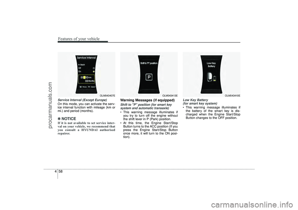
4Service Interval (Except Europe)On this mode, you can activate the serv-
ice interval function with mileage (km or
mi.) and period (months).✽ ✽
NOTICEIf it is not available to set service inter-
val on your vehicle, we recommend that
you consult a HYUNDAI authorised
repairer.
Warning Messages (if equipped)Shift to "P" position (for smart key
system and automatic transaxle) This warning message illuminates if you try to turn off the engine without
the shift lever in P (Park) position.
At this time, the Engine Start/Stop Button turns to the ACC position (If you
press the Engine Start/Stop Button
once more, it will turn to the ON posi-
tion).
Low Key Battery (for smart key system) This warning message illuminates if the battery of the smart key is dis-
charged when the Engine Start/Stop
Button changes to the OFF position.
OLM043407E
OLM043413E
OLM043410E
EL(FL) UK 4A.QXP 2/9/2015 9:04 PM Page 58
procarmanuals.com
Page 149 of 550
Features of your vehicle64
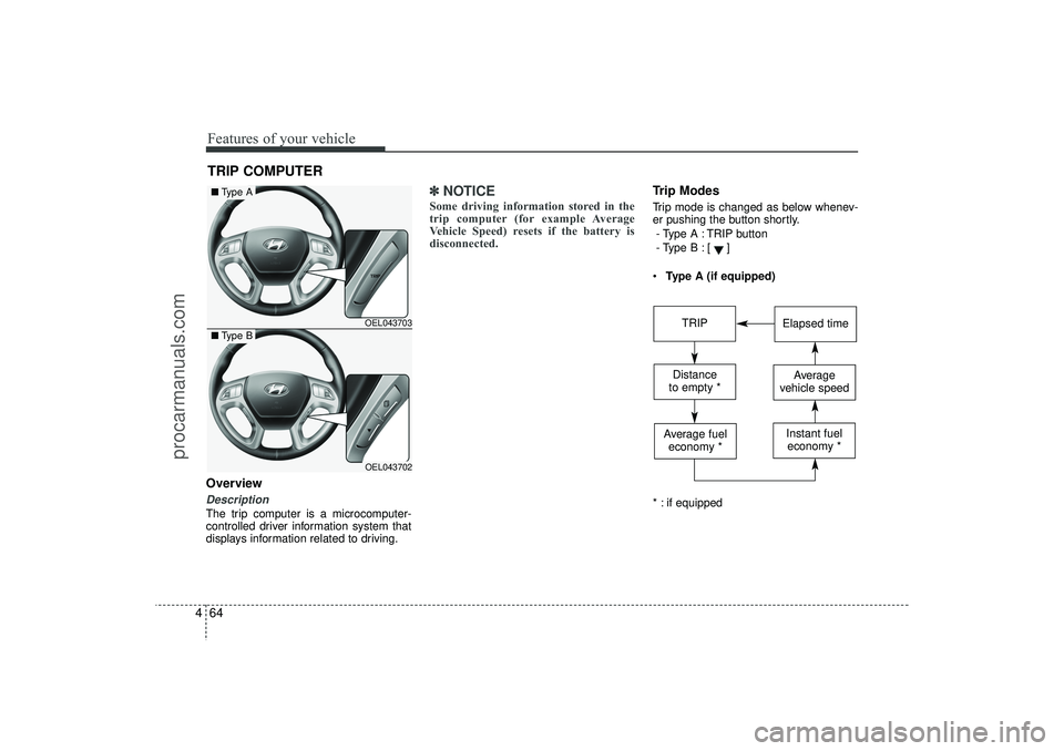
4OverviewDescriptionThe trip computer is a microcomputer-
controlled driver information system that
displays information related to driving.
✽ ✽
NOTICESome driving information stored in the
trip computer (for example Average
Vehicle Speed) resets if the battery is
disconnected.
Trip ModesTrip mode is changed as below whenev-
er pushing the button shortly.
- Type A : TRIP button
- Type B :
[]
Type A (if equipped)
* : if equipped
TRIP COMPUTER
OEL043703OEL043702
■ Type A■Type B
TRIP
Elapsed time
Distance
to empty *
Average
vehicle speed
Average fuel economy *
Instant fueleconomy *
EL(FL) UK 4A.QXP 2/9/2015 9:05 PM Page 64
procarmanuals.com
Page 150 of 550
465
Features of your vehicle
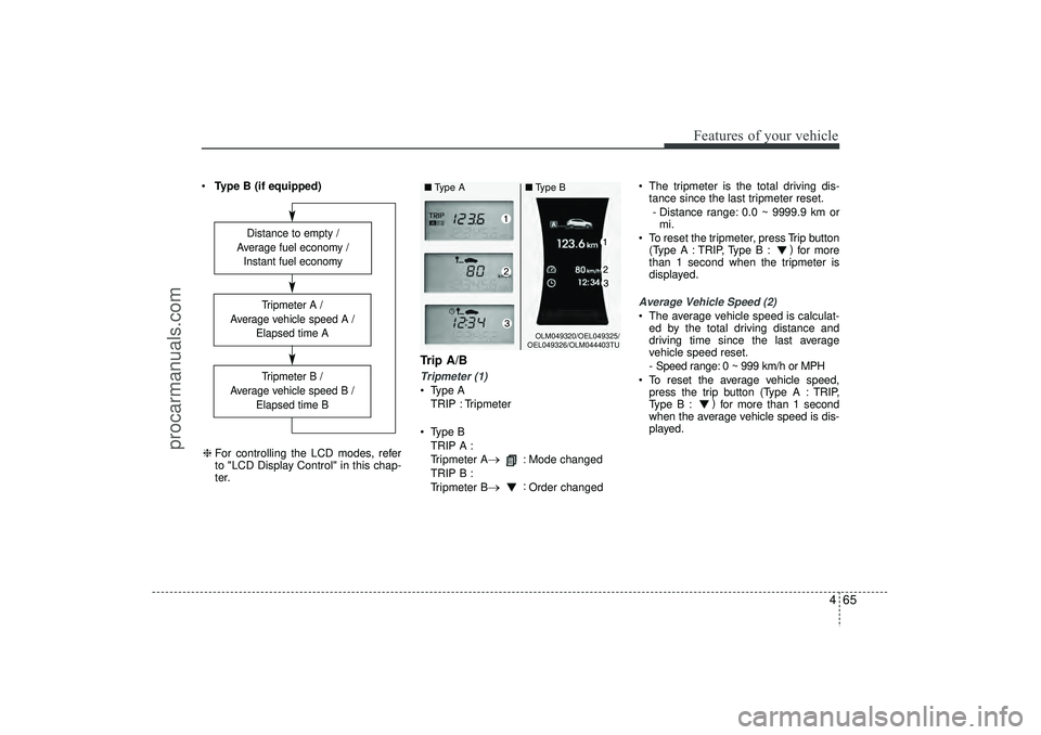
Type B (if equipped)
Trip A/BTripmeter (1) Type A
TRIP : Tripmeter
Type B TRIP A :
Tripmeter A
→
: Mode changed
TRIP B :
Tripmeter B
→
: Order changed The tripmeter is the total driving dis-
tance since the last tripmeter reset.
- Distance range: 0.0 ~ 9999.9 km or mi.
To reset the tripmeter, press Trip button (Type A : TRIP, Type B : )
for more
than 1 second when the tripmeter is
displayed.
Average Vehicle Speed (2) The average vehicle speed is calculat- ed by the total driving distance and
driving time since the last average
vehicle speed reset.
- Speed range: 0 ~ 999 km/h or MPH
To reset the average vehicle speed, press the trip button (Type A : TRIP,
Type B : )
for more than 1 second
when the average vehicle speed is dis-
played.
Distance to empty /
Average fuel economy / Instant fuel economy
Tripmeter B /
Average vehicle speed B / Elapsed time BTripmeter A /
Average vehicle speed A / Elapsed time A
❈For controlling the LCD modes, refer
to "LCD Display Control" in this chap-
ter.
OLM049320/OEL049325/
OEL049326/OLM044403TU
■ Type A ■Type B
EL(FL) UK 4A.QXP 2/9/2015 9:05 PM Page 65
procarmanuals.com
Page 187 of 550
Features of your vehicle102
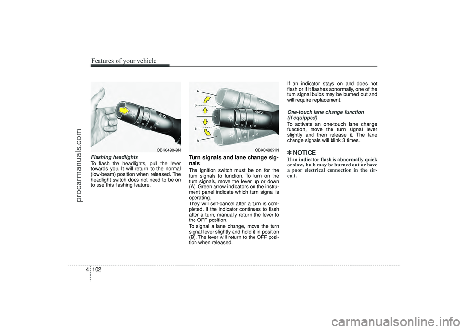
4Flashing headlights To flash the headlights, pull the lever
towards you. It will return to the normal
(low-beam) position when released. The
headlight switch does not need to be on
to use this flashing feature.
Turn signals and lane change sig-
nalsThe ignition switch must be on for the
turn signals to function. To turn on the
turn signals, move the lever up or down
(A). Green arrow indicators on the instru-
ment panel indicate which turn signal is
operating.
They will self-cancel after a turn is com-
pleted. If the indicator continues to flash
after a turn, manually return the lever to
the OFF position.
To signal a lane change, move the turn
signal lever slightly and hold it in position
(B). The lever will return to the OFF posi-
tion when released. If an indicator stays on and does not
flash or if it flashes abnormally, one of the
turn signal bulbs may be burned out and
will require replacement.
One-touch lane change function
(if equipped)To activate an one-touch lane change
function, move the turn signal lever
slightly and then release it. The lane
change signals will blink 3 times.✽ ✽ NOTICEIf an indicator flash is abnormally quick
or slow, bulb may be burned out or have
a poor electrical connection in the cir-
cuit.
OBK049051N
OBK049049N
EL(FL) UK 4A.QXP 2/9/2015 9:06 PM Page 102
procarmanuals.com
Page 207 of 550
Features of your vehicle122
4Air conditioning system operation tips
If the vehicle has been parked in direct
sunlight during hot weather, open the
windows for a short time to let the hot
air inside the vehicle escape.
To help reduce moisture inside of the windows on rainy or humid days,
decrease the humidity inside the vehi-
cle by operating the air conditioning
system.
During air conditioning system opera- tion, you may occasionally notice a
slight change in engine speed as the
air conditioning compressor cycles.
This is a normal system operation
characteristic.
Use the air conditioning system every month only for a few minutes to ensure
maximum system performance. When using the air conditioning sys-
tem, you may notice clear water drip-
ping (or even puddling) on the ground
under the passenger side of the vehi-
cle. This is a normal system operation
characteristic.
Operating the air conditioning system in the recirculated air position provides
maximum cooling, however, continual
operation in this mode may cause the
air inside the vehicle to become stale.
During cooling operation, you may occasionally notice a misty air flow
because of rapid cooling and humid air
intake. This is a normal system opera-
tion characteristic.
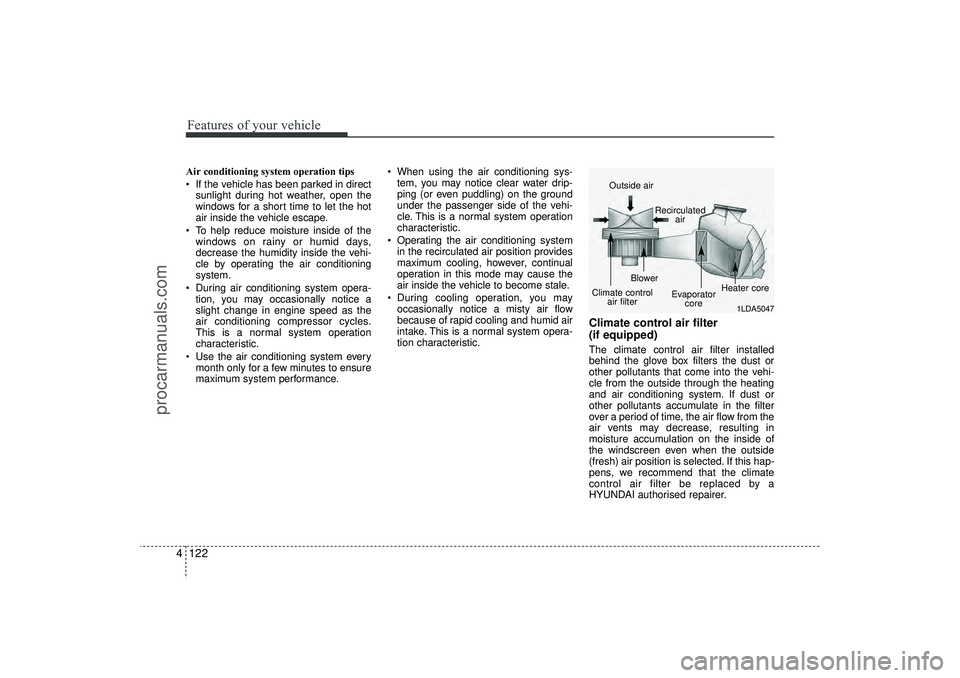
Climate control air filter
(if equipped)The climate control air filter installed
behind the glove box filters the dust or
other pollutants that come into the vehi-
cle from the outside through the heating
and air conditioning system. If dust or
other pollutants accumulate in the filter
over a period of time, the air flow from the
air vents may decrease, resulting in
moisture accumulation on the inside of
the windscreen even when the outside
(fresh) air position is selected. If this hap-
pens, we recommend that the climate
control air filter be replaced by a
HYUNDAI authorised repairer.
1LDA5047
Outside air
Recirculatedair
Climate control air filter Blower
Evaporatorcore Heater core
EL(FL) UK 4A.QXP 2/9/2015 9:08 PM Page 122
procarmanuals.com
Page 239 of 550
Features of your vehicle154
4✽
✽
NOTICE -
USING THE iPod
®
DEVICE
• Some iPod
®models may not sup-
port communication protocol and
files may not properly play.
Supported iPod
®models:
- iPod
®Mini
- iPod®4th (Photo) ~ 6th (Classic)
generation
- iPod®Nano 1st~4th generation
- iPod®Touch 1st~2nd generation
• The order of search or playback of songs in the iPod
®can be different
from the order searched in the
audio system.
• If the iPod
®
disabled due to its
own malfunction, reset the iPod
®.
(Reset: Refer to iPod
®manual)
• An iPod
®
may not operate nor-
mally on low battery. (Continued)(Continued)
• Some
iPod
®
devices, such as the
iPhone
®, can be connected through
the Bluetooth
®Wireless Technology
interface. The device must have
audio Bluetooth
®
Wireless
Technology capability (such as for
stereo headphone Bluetooth
®
Wireless Technology ). The device
can play, but it will not be con-
trolled by the audio system.
• To use iPod
®
features within the
audio, use the cable provided upon
purchasing an iPod
®d device.
• Skipping or improper operation may occur depending on the characteris-
tics of your iPod
®/iPhone
®device.
• If your iPhone
®is connected to both
the Bluetooth
®Wireless Technology
and USB, the sound may not be prop-
erly played. In your iPhone
®, select
the Dock connector or Bluetooth
®
Wireless Technology to change the
sound output (source). (Continued)
(Continued)
• When connecting
iPod
®
with the
iPod
®Power Cable, insert the connec-
tor to the multimedia socket complete-
ly. If not inserted completely, communi-
cations between
iPod
®and audio may
be interrupted.
• When adjusting the sound effects of the
iPod
®and the audio system, the
sound effects of both devices will over-
lap and might reduce or distort the
quality of the sound.
• Deactivate (turn off) the equalizer function of an
iPod
®when adjusting
the audio system’s volume, and turn
off the equalizer of the audio system
when using the equalizer of an
iPod
®.
• When not using
iPod
®with car audio,
detach the
iPod
®cable from
iPod
®.
Otherwise,
iPod
®
may remain in
accessory mode, and may not work
properly.
EL(FL) UK 4B AUDIO.QXP 3/13/2015 4:19 PM Page 154
procarmanuals.com