fuel cap Hyundai Kona 2018 Owner's Manual - RHD (UK, Australia)
[x] Cancel search | Manufacturer: HYUNDAI, Model Year: 2018, Model line: Kona, Model: Hyundai Kona 2018Pages: 497, PDF Size: 11.7 MB
Page 6 of 497
F6
Introduction
NOTICE indicates a situation
which, if not avoided, could result
in vehicle damage.
Petrol engine
Unleaded
For the optimal vehicle performance,
we recommend you use unleaded
petrol which has an octane rating of
RON (Research Octane Number) 95 /
AKI (Anti Knock Index) 91 or higher.
You may use unleaded petrol with an
octane rating of RON 91-94 / AKI 87-
90 but it may result in slight perform-
ance reduction of the vehicle. (Do not
use methanol blended fuels)
Your new vehicle is designed to
obtain maximum performance with
UNLEADED FUEL, as well as min-
imise exhaust emissions and spark
plug fouling.
NOTICE
CAUTION indicates a hazardous
situation which, if not avoided,
could result in minor or moder-
ate injury.
CAUTION
•Do not "top off" after the noz-
zle automatically shuts off
when refuelling.
•Always check that the fuel cap
is installed securely to pre-
vent fuel spillage in the event
of an accident.
WARNING
NEVER USE LEADED FUEL. The
use of leaded fuel is detrimental
to the catalytic converter and
will damage the engine control
system’s oxygen sensor and
affect emission control.
Never add any fuel system
cleaning agents to the fuel tank
other than what has been speci-
fied (We recommend that you
consult a HYUNDAI authorised
repairer for details.)
CAUTION
FUEL REQUIREMENTS
Page 113 of 497
3-35
Convenient features of your vehicle
3
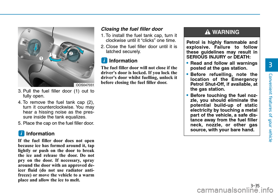
3. Pull the fuel filler door (1) out tofully open.
4. To remove the fuel tank cap (2), turn it counterclockwise. You may
hear a hissing noise as the pres-
sure inside the tank equalizes.
5. Place the cap on the fuel filler door.
Information
If the fuel filler door does not open
because ice has formed around it, tap
lightly or push on the door to break
the ice and release the door. Do not
pry on the door. If necessary, spray
around the door with an approved de-
icer fluid (do not use radiator anti-
freeze) or move the vehicle to a warm
place and allow the ice to melt.
Closing the fuel filler door
1. To install the fuel tank cap, turn it clockwise until it “clicks” one time.
2. Close the fuel filler door until it is latched securely.
Information
The fuel filler door will not close if the
driver's door is locked. If you lock the
driver's door whilst fuelling, unlock it
before closing the fuel filler door.
i
i
OOS047031
Petrol is highly flammable and
explosive. Failure to follow
these guidelines may result in
SERIOUS INJURY or DEATH:
•Read and follow all warnings
posted at the gas station.
•Before refuelling, note the
location of the Emergency
Petrol Shut-Off, if available, at
the gas station.
•Before touching the fuel noz-
zle, you should eliminate the
potential build-up of static
electricity by touching a metal
part of the vehicle, a safe dis-
tance away from the fuel filler
neck, nozzle, or other gas
source, with your bare hand.
WARNING
Page 114 of 497
3-36
Convenient features of your vehicle
•Use only approved portable
plastic fuel containers
designed to carry and store
petrol.
•Do not use matches or a
lighter and do not smoke or
leave a lit cigarette in your
vehicle whilst at a gas station,
especially during refuelling.
•Do not over-fill or top-off your
vehicle tank, which can cause
petrol spillage.
•If a fire breaks out during refu-
elling, leave the vicinity of the
vehicle, and immediately con-
tact the manager of the gas
station and then contact the
local fire department. Follow
any safety instructions they
provide.
•When refuelling, always move
the shift lever to the P (Park,
for dual clutch transmission)
or first gear or R (Reverse, for
manual transmission) posi-
tion, set the parking brake, and
place the ignition switch to the
LOCK/OFF position. Sparks
produced by electrical compo-
nents related to the engine can
ignite fuel
vapourscausing a
fire.
•When using an approved
portable fuel container, be
sure to place the container on
the ground prior to refuelling.
Static electricity discharge
from the container can ignite
fuel vapours causing a fire.
Once refuelling has begun,
contact between your bare
hand and the vehicle should
be maintained until the filling
is complete.
•Do not use mobile phones
whilst refuelling. Electric cur-
rent and/or electronic interfer-
ence from mobile phones can
potentially ignite fuel vapours
and cause a fire.
•Do not get back into a vehicle
once you have begun refu-
elling. You can generate a
build-up of static electricity by
touching, rubbing or sliding
against any item or fabric
capable of producing static
electricity.
Static electricity discharge
can ignite fuel vapours caus-
ing a fire. If you must re-enter
the vehicle, you should once
again eliminate potentially
dangerous static electricity
discharge by touching a metal
part of the vehicle, away from
the fuel filler neck, nozzle or
other petrol source, with your
bare hand.
Page 115 of 497
3-37
Convenient features of your vehicle
Information
Make sure to refuel your vehicle
according to the "Fuel Requirements"
suggested in the Introduction chapter.
• Do not spill fuel on the exteriorsurfaces of the vehicle. Any type
of fuel spilled on painted sur-
faces may damage the paint.
• If the fuel filler cap requires replacement, use only a genuine
HYUNDAI cap or the equivalent
specified for your vehicle. An
incorrect fuel filler cap can
result in a serious malfunction
of the fuel system or emission
control system.
NOTICE
i
3
•If pressurised fuel sprays out,
it can cover your clothes or
skin and thus subject you to
the risk of fire and burns.
Always remove the fuel cap
carefully and slowly. If the cap
is venting fuel or if you hear a
hissing sound, wait until the
condition stops before com-
pletely removing the cap.
•Always check that the fuel cap
is installed securely to pre-
vent fuel spillage in the event
of an accident.
Page 118 of 497
3-40
Convenient features of your vehicle
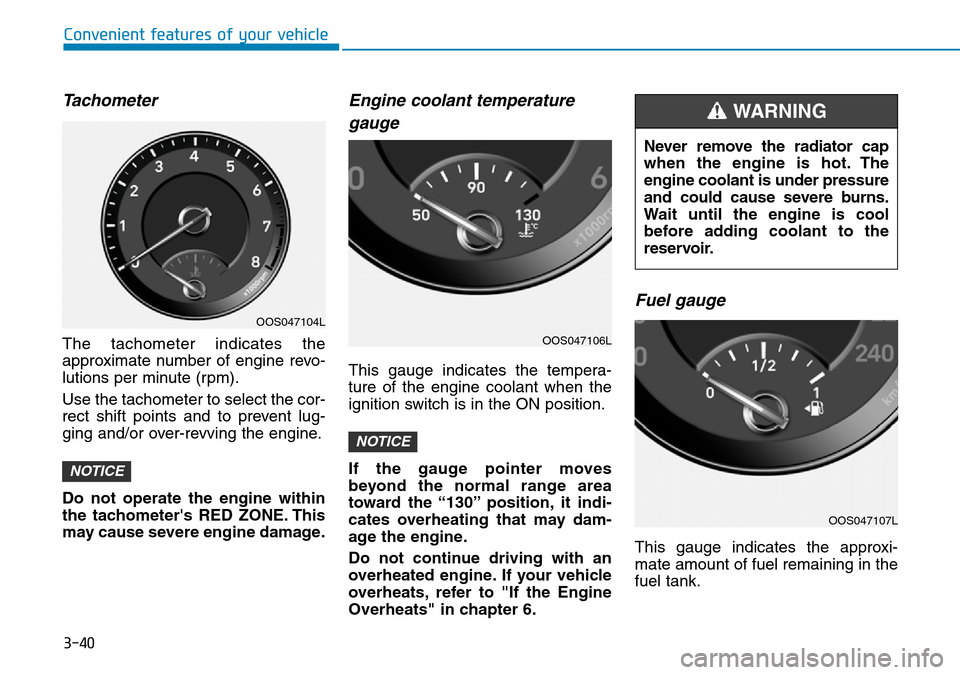
Tachometer
The tachometer indicates the
approximate number of engine revo-
lutions per minute (rpm).
Use the tachometer to select the cor-
rect shift points and to prevent lug-
ging and/or over-revving the engine.
Do not operate the engine within
the tachometer's RED ZONE. This
may cause severe engine damage.
Engine coolant temperaturegauge
This gauge indicates the tempera-
ture of the engine coolant when the
ignition switch is in the ON position.
If the gauge pointer moves
beyond the normal range area
toward the “130” position, it indi-
cates overheating that may dam-
age the engine.
Do not continue driving with an
overheated engine. If your vehicle
overheats, refer to "If the Engine
Overheats" in chapter 6.
Fuel gauge
This gauge indicates the approxi-
mate amount of fuel remaining in the
fuel tank.
NOTICE
NOTICE
OOS047104L
OOS047106L
Never remove the radiator cap
when the engine is hot. The
engine coolant is under pressure
and could cause severe burns.
Wait until the engine is cool
before adding coolant to the
reservoir.
WARNING
OOS047107L
Page 119 of 497
3-41
Convenient features of your vehicle
3
Information
• The fuel tank capacity is given inchapter 8.
• The fuel gauge is supplemented by a low fuel warning light, which will
illuminate when the fuel tank is
nearly empty.
• On inclines or curves, the fuel gauge pointer may fluctuate or the low fuel
warning light may come on earlier
than usual due to the movement of
fuel in the tank.
Avoid driving with an extremely
low fuel level. Running out of fuel
could cause the engine to misfire
damaging the catalytic converter.
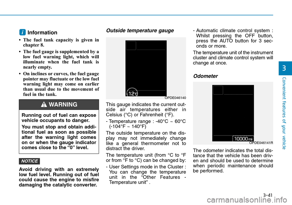
Outside temperature gauge
This gauge indicates the current out-
side air temperatures either in
Celsius (°C) or Fahrenheit (°F).
- Temperature range : -40°C ~ 60°C (-104°F ~ 140°F)
The outside temperature on the dis-
play may not immediately change
like a general thermometer not to
distract the driver.
The temperature unit (from °C to °F
or from °F to °C) can be changed by:
- User Settings mode in the Cluster : You can change the temperature
unit in the “Other Features -
Temperature unit” . - Automatic climate control system :
Whilst pressing the OFF button,
press the AUTO button for 3 sec-
onds or more.
The temperature unit of the instrument
cluster and climate control system will
change at once.
Odometer
The odometer indicates the total dis-
tance that the vehicle has been driv-
en and should be used to determine
when periodic maintenance should
be performed.
NOTICE
i
Running out of fuel can expose
vehicle occupants to danger.
You must stop and obtain addi-
tional fuel as soon as possible
after the warning light comes
on or when the gauge indicator
comes close to the “0” level.
WARNING
OPDE046140
OPDE046141R
Page 128 of 497
3-50
Convenient features of your vehicle
Engine Oil LevelWarning Light(if equipped)
The engine oil level warning light illu-
minates when the engine oil level
should be checked.
If the warning light comes on, check
the engine oil level as soon as possi-
ble and add engine oil as required.
Slowly pour the recommended oil lit-
tle by little into a funnel. (Oil refill
capacity : approximately 0.6 ~ 1.0 l)
Use only the specified engine oil.
(Refer to "Recommended lubricants
and capacities" in chapter 8.)
Do not overfill the engine oil. Make
sure the oil level is not above F (Full)
mark on the dipstick.
Information
• If you travel approximately 30 ~ 60
miles (50 km ~100 km) after the
engine warms up, after adding the
engine oil, the warning light will go
off.
• Cycle the ignition from OFF to ON 3 times within 10 seconds, the warning
light will go off immediately. However,
when you turn off the warning light
without adding the engine oil, the light
will come on again after travelling
approximately 30 ~ 60 miles (50 ~ 100
km) after the engine warms up.
If the light comes on continuously
after adding the engine oil and
travelling approximately 30 ~ 60
miles (50 ~ 100 km) after the
engine warms up, we recommend
that the system be checked by a
HYUNDAI authorised repairer.
Even if this light doesn't come on
after the engine has started, the
engine oil should be checked and
supplied periodically.
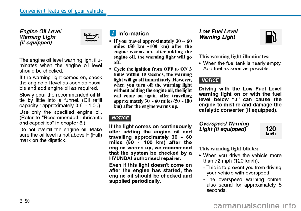
Low Fuel Level Warning Light
This warning light illuminates:
• When the fuel tank is nearly empty.
Add fuel as soon as possible.
Driving with the Low Fuel Level
warning light on or with the fuel
level below “0” can cause the
engine to misfire and damage the
catalytic converter (if equipped).
Overspeed Warning Light (if equipped)
This warning light blinks:
• When you drive the vehicle more
than 72 mph (120 km/h).
- This is to prevent you from drivingyour vehicle with overspeed.
- The overspeed warning chime also sound for approximately 5
seconds.
NOTICE
NOTICE
i
120km/h
Page 415 of 497
7-8
Maintenance
EXPLANATION OF SCHEDULED MAINTENANCE ITEMS
Engine oil and filter
The engine oil and filter should be
changed at the intervals specified in
the maintenance schedule. If the
vehicle is being driven in severe con-
ditions, more frequent oil and filter
changes are required.
Drive belts
Inspect all drive belts for evidence of
cuts, cracks, excessive wear or oil
saturation and replace if necessary.
Drive belts should be checked peri-
odically for proper tension and
adjusted as necessary.
Fuel lines, fuel hoses and con-
nections
Check the fuel lines, fuel hoses and
connections for leakage and dam-
age. We recommend that the fuel
lines, fuel hoses and connections be
replaced by a HYUNDAI authorised
repairer.
Fuel filter (for Petrol Engine)
HYUNDAI petrol vehicle is equipped
a lifetime fuel filter that integrated
with the fuel tank. Regular mainte-
nance or replacement is not needed
but depends on fuel quality. If there
are some important safety matters
like fuel flow restriction, surging, loss
of power, hard starting problem etc,
fuel filter inspection or replace is
needed. We recommend that the fuel
filter be Inspected or replaced by a
HYUNDAI authorised repairer.
Vapour hose and fuel filler cap
The vapour hose and fuel filler cap
should be inspected at those inter-
vals specified in the maintenance
schedule. Make sure that a new
vapour hose or fuel filler cap is cor-
rectly replaced.
Vacuum crankcase ventilation
hoses (if equipped)
Inspect the surface of hoses for evi-
dence of heat and/or mechanical
damage. Hard and brittle rubber,
cracking, tears, cuts, abrasions, and
excessive swelling indicate deterio-
ration. Particular attention should be
paid to examine those hose surfaces
nearest to high heat sources, such
as the exhaust manifold.
Inspect the hose routing to ensure
that the hoses do not come in con-
tact with any heat source, sharp
edges or moving component which
might cause heat damage or
mechanical wear. Inspect all hose
connections, such as clamps and
couplings, to make sure they are
secure, and that no leaks are pres-
ent. Hoses should be replaced
immediately if there is any evidence
of deterioration or damage.
When you are inspecting the belt,
place the ignition switch to the
LOCK/OFF or ACC position.
CAUTION
Page 483 of 497
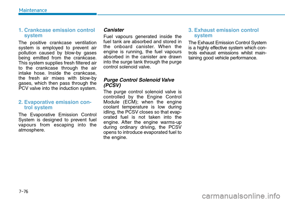
7-76
Maintenance
1. Crankcase emission controlsystem
The positive crankcase ventilation
system is employed to prevent air
pollution caused by blow-by gases
being emitted from the crankcase.
This system supplies fresh filtered air
to the crankcase through the air
intake hose. Inside the crankcase,
the fresh air mixes with blow-by
gases, which then pass through the
PCV valve into the induction system.
2. Evaporative emission con-trol system
The Evaporative Emission Control
System is designed to prevent fuel
vapours from escaping into the
atmosphere.
Canister
Fuel vapours generated inside the
fuel tank are absorbed and stored in
the onboard canister. When the
engine is running, the fuel vapours
absorbed in the canister are drawn
into the surge tank through the purge
control solenoid valve.
Purge Control Solenoid Valve
(PCSV)
The purge control solenoid valve is
controlled by the Engine Control
Module (ECM); when the engine
coolant temperature is low during
idling, the PCSV closes so that evap-
orated fuel is not taken into the
engine. After the engine warms-up
during ordinary driving, the PCSV
opens to introduce evaporated fuel to
the engine.
3. Exhaust emission control system
The Exhaust Emission Control System
is a highly effective system which con-
trols exhaust emissions whilst main-
taining good vehicle performance.
Page 492 of 497
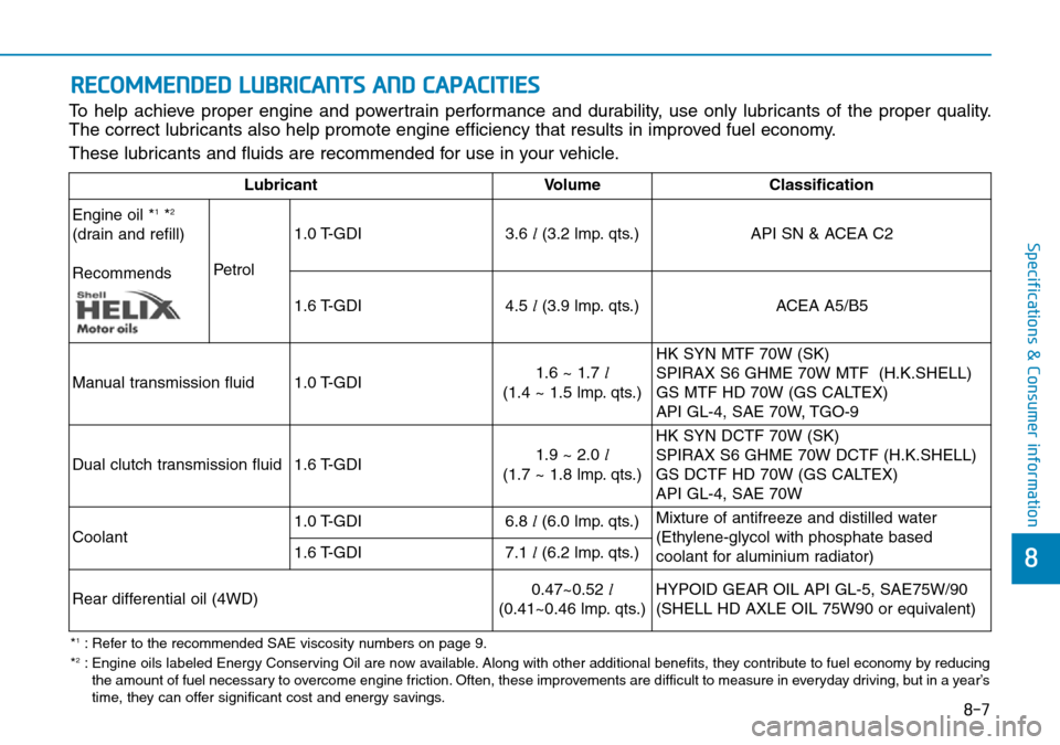
8
Specifications & Consumer information
RECOMMENDED LUBRICANTS AND CAPACITIES
To help achieve proper engine and powertrain performance and durability, use only lubricants of the proper quality.
The correct lubricants also help promote engine efficiency that results in improved fuel economy.
These lubricants and fluids are recommended for use in your vehicle.
LubricantVolumeClassification
Engine oil *
1*2
(drain and refill)
Recommends Petrol1.0 T-GDI
3.6
l(3.2 lmp. qts.)
API SN & ACEA C2
1.6 T-GDI 4.5
l(3.9 lmp. qts.)
ACEA A5/B5
Manual transmission fluid 1.0 T-GDI 1.6 ~ 1.7 l
(1.4 ~ 1.5 lmp. qts.) HK SYN MTF 70W (SK)
SPIRAX S6 GHME 70W MTF (H.K.SHELL)
GS MTF HD 70W (GS CALTEX)
API GL-4, SAE 70W, TGO-9
Dual clutch transmission fluid 1.6 T-GDI 1.9 ~ 2.0 l
(1.7 ~ 1.8 lmp. qts.) HK SYN DCTF 70W (SK)
SPIRAX S6 GHME 70W DCTF (H.K.SHELL)
GS DCTF HD 70W (GS CALTEX)
API GL-4, SAE 70W
Coolant 1.0 T-GDI
6.8
l(6.0 lmp. qts.) Mixture of antifreeze and distilled water
(Ethylene-glycol with phosphate based
coolant for aluminium radiator)
1.6 T-GDI
7.1
l(6.2 lmp. qts.)
Rear differential oil (4WD) 0.47~0.52
l
(0.41~0.46 lmp. qts.) HYPOID GEAR OIL API GL-5, SAE75W/90
(SHELL HD AXLE OIL 75W90 or equivalent)
*1: Refer to the recommended SAE viscosity numbers on page 9.
*2: Engine oils labeled Energy Conserving Oil are now available. Along with other additional benefits, they contribute to fuel economy by reducing the amount of fuel necessary to overcome engine friction. Often, these improvements are difficult to measure in everyday driving, but in a year’s
time, they can offer significant cost and energy savings.
8-7