lock Hyundai Kona 2020 Owner's Manual
[x] Cancel search | Manufacturer: HYUNDAI, Model Year: 2020, Model line: Kona, Model: Hyundai Kona 2020Pages: 505, PDF Size: 13.47 MB
Page 462 of 505
7-71
7
Maintenance
5. Remove the bulb from the head-lamp assembly.
6. Install a new headlamp bulb and snap the headlamp bulb retaining
wire into position by aligning the
wire with the groove on the bulb.
7. Connect the headlamp bulb sock- et-connector.
8. Install the headlamp bulb cover by turning it clockwise.
Information
The headlamp aiming should be
adjusted after an accident or after the
headlamp assembly is reinstalled at an
authorized HYUNDAI dealer.
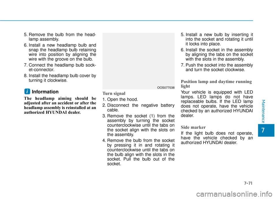
Turn signal
1. Open the hood.
2. Disconnect the negative batterycable.
3. Remove the socket (1) from the assembly by turning the socket
counterclockwise until the tabs on
the socket align with the slots on
the assembly.
4. Remove the bulb from the socket by pressing it in and rotating it
counterclockwise until the tabs on
the bulb align with the slots in the
socket. Pull the bulb out of the
socket. 5. Install a new bulb by inserting it
into the socket and rotating it until
it locks into place.
6. Install the socket in the assembly by aligning the tabs on the socket
with the slots in the assembly.
7. Push the socket into the assembly and turn the socket clockwise.
Position lamp and daytime running
light
Your vehicle is equipped with LED
lamps. LED lamps do not have
replaceable bulbs. If the LED lamp
does not operate, have the vehicle
checked by an authorized HYUNDAI
dealer.
Side marker
If the light bulb does not operate,
have the vehicle checked by an
authorized HYUNDAI dealer.
iOOS077038
Page 464 of 505
7-73
7
Maintenance
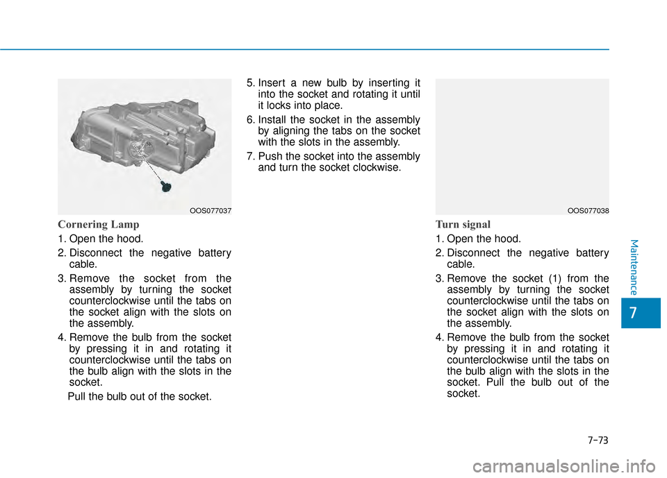
Cornering Lamp
1. Open the hood.
2. Disconnect the negative batterycable.
3. Remove the socket from the assembly by turning the socket
counterclockwise until the tabs on
the socket align with the slots on
the assembly.
4. Remove the bulb from the socket by pressing it in and rotating it
counterclockwise until the tabs on
the bulb align with the slots in the
socket.
Pull the bulb out of the socket. 5. Insert a new bulb by inserting it
into the socket and rotating it until
it locks into place.
6. Install the socket in the assembly by aligning the tabs on the socket
with the slots in the assembly.
7. Push the socket into the assembly and turn the socket clockwise.
Turn signal
1. Open the hood.
2. Disconnect the negative batterycable.
3. Remove the socket (1) from the assembly by turning the socket
counterclockwise until the tabs on
the socket align with the slots on
the assembly.
4. Remove the bulb from the socket by pressing it in and rotating it
counterclockwise until the tabs on
the bulb align with the slots in the
socket. Pull the bulb out of the
socket.
OOS077038OOS077037
Page 465 of 505
7-74
Maintenance
5. Install a new bulb by inserting it into the socket and rotating it until
it locks into place.
6. Install the socket in the assembly by aligning the tabs on the socket
with the slots in the assembly.
7. Push the socket into the assembly and turn the socket clockwise.
Position lamp and daytime running
light
Your vehicle is equipped with LED
lamps. LED lamps do not have
replaceable bulbs. If the LED lamp
does not operate, have the vehicle
checked by an authorized HYUNDAI
dealer.
Side marker
If the light bulb does not operate,
have the vehicle checked by an
authorized HYUNDAI dealer.
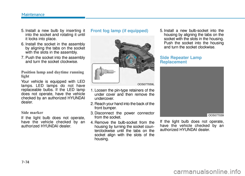
Front fog lamp (if equipped)
1. Loosen the pin-type retainers of theunder cover and then remove the
undercover.
2. Reach your hand into the back of the front bumper.
3. Disconnect the power connector from the socket.
4. Remove the bulb-socket from the housing by turning the socket coun-
terclockwise until the tabs on the
socket align with the slots of the
housing. 5. Install a new bulb-socket into the
housing by aligning the tabs on the
socket with the slots in the housing.
Push the socket into the housing
and turn the socket clockwise.
Side Repeater Lamp
Replacement
If the light bulb does not operate,
have the vehicle checked by an
authorized HYUNDAI dealer.
OOS077039
OOS077059L
Page 467 of 505
7-76
Maintenance
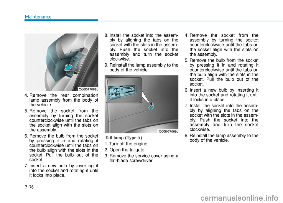
4. Remove the rear combination lamp assembly from the body of
the vehicle.
5. Remove the socket from the assembly by turning the socket
counterclockwise until the tabs on
the socket align with the slots on
the assembly.
6. Remove the bulb from the socket by pressing it in and rotating it
counterclockwise until the tabs on
the bulb align with the slots in the
socket. Pull the bulb out of the
socket.
7. Insert a new bulb by inserting it into the socket and rotating it until
it locks into place. 8. Install the socket into the assem-
bly by aligning the tabs on the
socket with the slots in the assem-
bly. Push the socket into the
assembly and turn the socket
clockwise.
9. Reinstall the lamp assembly to the body of the vehicle.
Tail lamp (Type A)
1. Turn off the engine.
2. Open the tailgate.
3. Remove the service cover using aflat-blade screwdriver. 4. Remove the socket from the
assembly by turning the socket
counterclockwise until the tabs on
the socket align with the slots on
the assembly.
5. Remove the bulb from the socket by pressing it in and rotating it
counterclockwise until the tabs on
the bulb align with the slots in the
socket. Pull the bulb out of the
socket.
6. Insert a new bulb by inserting it into the socket and rotating it until
it locks into place.
7. Install the socket into the assem- bly by aligning the tabs on the
socket with the slots in the assem-
bly. Push the socket into the
assembly and turn the socket
clockwise.
8. Reinstall the lamp assembly to the body of the vehicle.
OOS077068L
OOS077069L
Page 494 of 505
8-11
88
Specifications, Consumer information and Reporting safety defects
The tires supplied on your new vehi-
cle are chosen to provide the best
performance for normal driving.
The tire label located on the driver’s
side center pillar gives the tire pres-
sures recommended for your car.The engine number is stamped on
the engine block as shown in the
drawing.
E EN
N G
GI
IN
N E
E
N
N U
U M
M B
BE
ER
R
T
T I
IR
R E
E
S
S P
P E
EC
CI
IF
F I
IC
C A
A T
TI
IO
O N
N
A
A N
N D
D
P
P R
R E
ES
SS
SU
U R
RE
E
L
L A
A B
BE
EL
L
OOS087003
OOS087004
■ Gamma 1.6 T-GDI
OAD085009L
■Nu 2.0 MPI
Page 499 of 505
I-3
Braking system ...............................................................5-29Anti-lock Brake System (ABS)..................................5-32
Disc Brakes Wear Indicator........................................5-30
Downhill Brake Control (DBC) .................................5-37
Electronic Stability Control (ESC).............................5-34
Good Braking Practices..............................................5-39
Hill-Start Assist Control (HAC) .................................5-37
Parking Brake .............................................................5-30
Power Brakes..............................................................5-29
Vehicle Stability Management (VSM) .......................5-36
Bulb Wattage .....................................................................8-3\
California perchlorate notice ..........................................7-92
Child Restraint System (CRS) ........................................2-34 Children Always in the Rear ......................................2-34
Installing a Child Restraint System (CRS) ................2-37
Selecting a Child Restraint System (CRS).................2-35
Climate Control Additional Features ............................3-132 Automatic Ventilation...............................................3-132
Cluster ionizer ..........................................................3-132
Sunroof Inside Air Recirculation .............................3-132
Climate control air filter .................................................7-30 Filter Inspection..........................................................7-30
Consumer Information ....................................................8-12
Cruise control..................................................................5-92 Cruise Control operation ............................................5-92 Dimensions .......................................................................8\
-2
Door Locks .....................................................................3-1\
3
Automatic Door Lock and Unlock Features ..............3-16
Child-Protector Rear Door Locks ..............................3-17
Operating Door Locks from Inside the Vehicle .........3-14
Operating Door Locks from Outside the Vehicle ......3-13
Drive Mode Integrated Control System .........................5-46
Driver Assist System.....................................................3-105 Parking Distance Warning (Reverse) system ...........3-106
Parking Distance Warning (Reverse) system Precautions ............................................................3-109
Rear view monitor ....................................................3-105
Driver Attention Warning (DAW) system ......................5-88 Resetting the System ..................................................5-89
System Malfunction ...................................................5-90
System Setting and Activation ...................................5-88
System Standby ..........................................................5-90
Dual clutch transmission.................................................5-20 Dual Clutch Transmission Operation .........................5-20
Good Driving Practices ..............................................5-27
I
Index
C
D
Page 501 of 505
I-5
If the engine overheats ......................................................6-6
If the engine will not start.................................................6-3If the Engine Doesn't Turn Over or Turns Over Slowly ....................................................6-3
If the Engine Turns Over Normally but Doesn't Start ........................................................6-3
If you have a flat tire (With spare tire) ...........................6-14 Changing Tires ...........................................................6-15
Jack and Tools ............................................................6-14
If you have a flat tire (with tire mobility kit) .................6-20 Checking the tire inflation pressure ...........................6-25
Components of the Tire Mobility Kit.........................6-22
Distributing the sealant ..............................................6-24
Introduction ................................................................6-20
Notes on the safe use of the Tire Mobility Kit ..........6-21
Using the Tire Mobility Kit........................................6-23
Ignition switch ..................................................................5-6 Engine Start/Stop Button ..............................................5-9
Key Ignition Switch .....................................................5-6
Important Safety Precautions............................................2-2 Air Bag Hazards ...........................................................2-2
Always Wear Your Seat Belt ........................................2-2
Control Your Speed ......................................................2-2
Driver Distraction.........................................................2-2
Keep Your Vehicle in Safe Condition ..........................2-2
Restrain All Children....................................................2-2 Infotainment System .........................................................4-2
Antenna ........................................................................\
4-2
Audio (Display Audio) / Video / Navigation System (AVN) .......................................4-4
AUX, USB and iPod
®Port ..........................................4-2
Bluetooth®Wireless Technology Hands-Free ..............4-4
Steering Wheel Audio Controls....................................4-3
In case of an emergency while driving .............................6-2 If the Engine Stalls at a Crossroad or Crossing ...........6-2
If the Engine Stalls While Driving...............................6-2
If you Have a Flat Tire While Driving.........................6-3
Instrument Cluster...........................................................3-49 Gauges and Meters .....................................................3-51
Instrument Cluster Control .........................................3-50
LCD Display Messages ..............................................3-67
Transmission shift indicator .......................................3-54
Warning and Indicator Lights.....................................3-55
Instrument Panel Overview ..............................................1-5
Interior Features ............................................................3-135 Cargo Area Cover .....................................................3-142
Clock ........................................................................\
3-140
Clothes Hanger .........................................................3-140
Cup Holder ...............................................................3-135
Floor Mat Anchor(s) .................................................3-141
Luggage Net Holder .................................................3-141
Luggage tray.............................................................3-144
Power Outlet.............................................................3-137
Sunvisor ....................................................................3-13\
6
Wireless Cellular Phone Charging System ..............3-138
I
Index
I