glove box HYUNDAI KONA EV 2021 Owners Manual
[x] Cancel search | Manufacturer: HYUNDAI, Model Year: 2021, Model line: KONA EV, Model: HYUNDAI KONA EV 2021Pages: 478, PDF Size: 32.83 MB
Page 14 of 478
I IN
NS
ST
TR
RU
UM
ME
EN
NT
T
P
PA
AN
NE
EL
L
O
OV
VE
ER
RV
VI
IE
EW
W
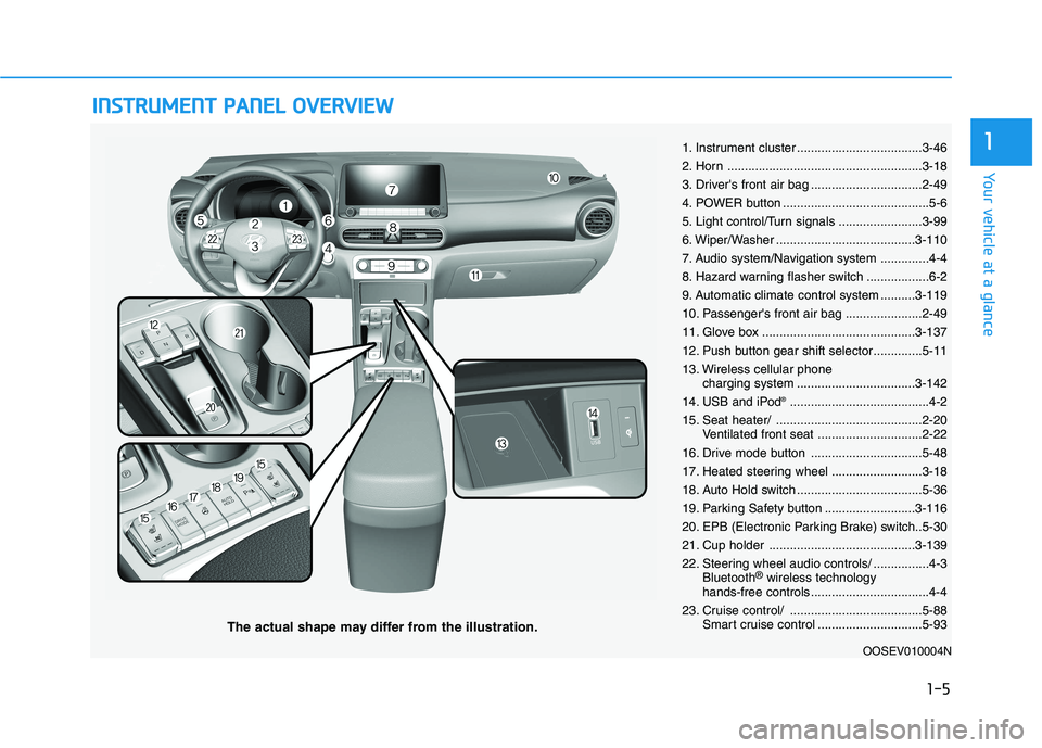
The actual shape may differ from the illustration.
1-5
Your vehicle at a glance
11. Instrument cluster ....................................3-46
2. Horn ........................................................3-18
3. Driver's front air bag ................................2-49
4. POWER button ..........................................5-6
5. Light control/Turn signals ........................3-99
6. Wiper/Washer ........................................3-110
7. Audio system/Navigation system ..............4-4
8. Hazard warning flasher switch ..................6-2
9. Automatic climate control system ..........3-119
10. Passenger's front air bag ......................2-49
11. Glove box ............................................3-137
12. Push button gear shift selector..............5-11
13. Wireless cellular phone
charging system ..................................3-142
14. USB and iPod
®........................................4-2
15. Seat heater/ ..........................................2-20
Ventilated front seat ..............................2-22
16. Drive mode button ................................5-48
17. Heated steering wheel ..........................3-18
18. Auto Hold switch ....................................5-36
19. Parking Safety button ..........................3-116
20. EPB (Electronic Parking Brake) switch..5-30
21. Cup holder ..........................................3-139
22. Steering wheel audio controls/ ................4-3
Bluetooth
®wireless technology
hands-free controls ..................................4-4
23. Cruise control/ ......................................5-88
Smart cruise control ..............................5-93
OOSEV010004N
Page 64 of 478
2-49
Safety system of your vehicle
2
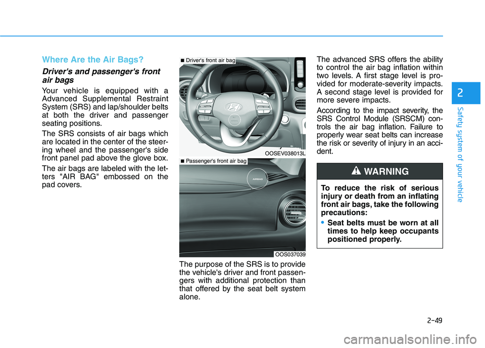
Where Are the Air Bags?
Driver's and passenger's front
air bags
Your vehicle is equipped with a
Advanced Supplemental Restraint
System (SRS) and lap/shoulder belts
at both the driver and passenger
seating positions.
The SRS consists of air bags which
are located in the center of the steer-
ing wheel and the passenger's side
front panel pad above the glove box.
The air bags are labeled with the let-
ters "AIR BAG" embossed on the
pad covers.
The purpose of the SRS is to provide
the vehicle's driver and front passen-
gers with additional protection than
that offered by the seat belt system
alone.The advanced SRS offers the ability
to control the air bag inflation within
two levels. A first stage level is pro-
vided for moderate-severity impacts.
A second stage level is provided for
more severe impacts.
According to the impact severity, the
SRS Control Module (SRSCM) con-
trols the air bag inflation. Failure to
properly wear seat belts can increase
the risk or severity of injury in an acci-
dent.
OOSEV038013L
OOS037039
■Driver's front air bag
■Passenger's front air bag
To reduce the risk of serious
injury or death from an inflating
front air bags, take the following
precautions:
Seat belts must be worn at all
times to help keep occupants
positioned properly.
WARNING
Page 65 of 478
![HYUNDAI KONA EV 2021 Owners Manual 2-50
Safety system of your vehicle
Side air bags ]
Your vehicle is equipped with a side
air bag in each front seat.The purpose of the air bag is to pro-
vide the vehicles driver and the front
passeng HYUNDAI KONA EV 2021 Owners Manual 2-50
Safety system of your vehicle
Side air bags ]
Your vehicle is equipped with a side
air bag in each front seat.The purpose of the air bag is to pro-
vide the vehicles driver and the front
passeng](/img/35/56172/w960_56172-64.png)
2-50
Safety system of your vehicle
Side air bags ]
Your vehicle is equipped with a side
air bag in each front seat.The purpose of the air bag is to pro-
vide the vehicle's driver and the front
passenger with additional protection
than that offered by the seat belt
alone.
The side air bags are designed to
deploy during certain side impact col-
lisions, depending on the crash sever-
ity.
The side and curtain air bags on
both sides of the vehicle may deploy
if a rollover or possible rollover is
detected.
The side air bags are not designed to
deploy in all side impact or rollover
situations.
OOS037040
OOS037041
To reduce the risk of serious
injury or death from an inflating
side air bag, take the following
precautions:
Seat belts must be worn at all
times to help keep occupants
positioned properly.
WARNING
Move your seat as far back as
possible from front air bags,
while still maintaining control
of the vehicle.
Never lean against the door or
center console.
Do not allow the front passen-
ger to place their feet or legs
on the dashboard.
No objects (such as crash pad
cover, cellular phone holder,
cup holder, perfume or stick-
ers) should be placed over or
near the air bag modules on
the steering wheel, instrument
panel, windshield glass, and
the front passenger's panel
above the glove box. Such
objects could cause harm if
the vehicle is in a crash
severe enough to cause the
air bags to deploy.
Do not attach any objects on
front windshield and inside
mirror.
Page 71 of 478
2-56
Safety system of your vehicle
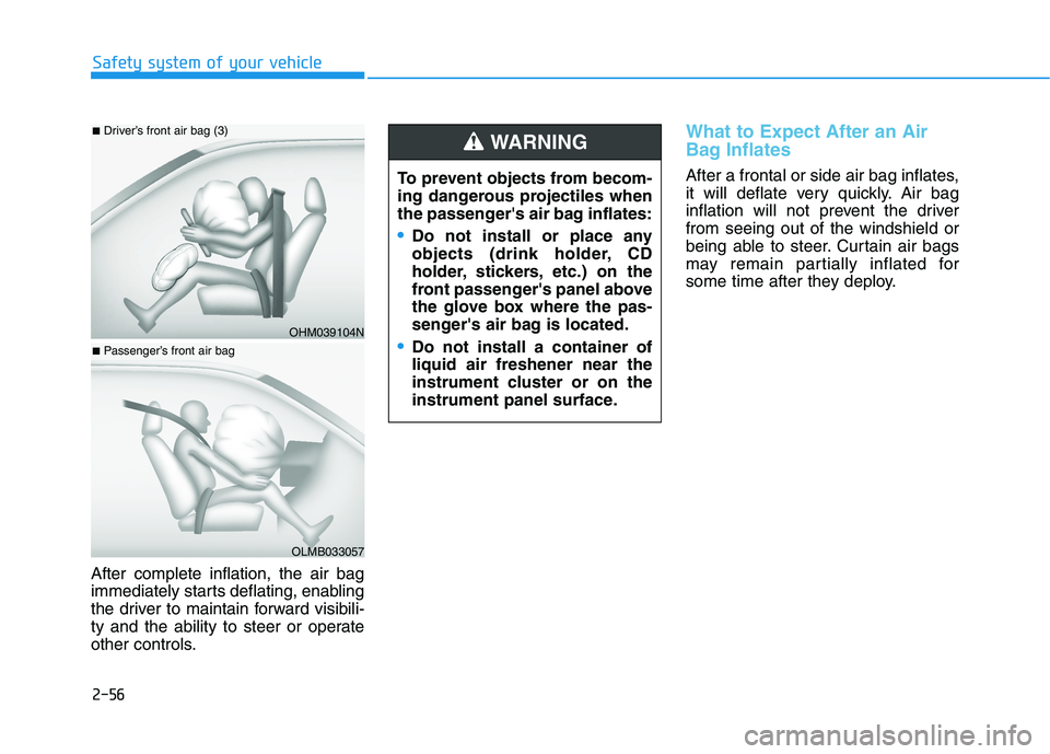
After complete inflation, the air bag
immediately starts deflating, enabling
the driver to maintain forward visibili-
ty and the ability to steer or operate
other controls.
What to Expect After an Air
Bag Inflates
After a frontal or side air bag inflates,
it will deflate very quickly. Air bag
inflation will not prevent the driver
from seeing out of the windshield or
being able to steer. Curtain air bags
may remain partially inflated for
some time after they deploy.
OHM039104N
■Driver’s front air bag (3)
OLMB033057
■Passenger’s front air bag
To prevent objects from becom-
ing dangerous projectiles when
the passenger's air bag inflates:
Do not install or place any
objects (drink holder, CD
holder, stickers, etc.) on the
front passenger's panel above
the glove box where the pas-
senger's air bag is located.
Do not install a container of
liquid air freshener near the
instrument cluster or on the
instrument panel surface.
WARNING
Page 83 of 478
2-68
Safety system of your vehicle
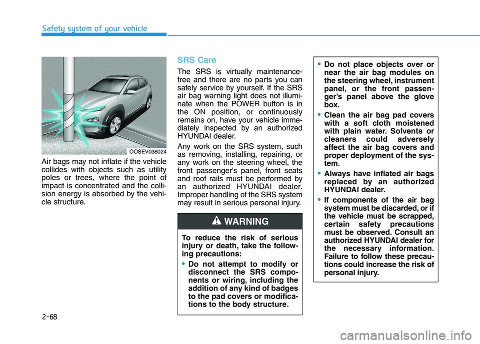
Air bags may not inflate if the vehicle
collides with objects such as utility
poles or trees, where the point of
impact is concentrated and the colli-
sion energy is absorbed by the vehi-
cle structure.
SRS Care
The SRS is virtually maintenance-
free and there are no parts you can
safely service by yourself. If the SRS
air bag warning light does not illumi-
nate when the POWER button is in
the ON position, or continuously
remains on, have your vehicle imme-
diately inspected by an authorized
HYUNDAI dealer.
Any work on the SRS system, such
as removing, installing, repairing, or
any work on the steering wheel, the
front passenger's panel, front seats
and roof rails must be performed by
an authorized HYUNDAI dealer.
Improper handling of the SRS system
may result in serious personal injury.
To reduce the risk of serious
injury or death, take the follow-
ing precautions:
Do not attempt to modify or
disconnect the SRS compo-
nents or wiring, including the
addition of any kind of badges
to the pad covers or modifica-
tions to the body structure.
WARNING
OOSEV038024
Do not place objects over or
near the air bag modules on
the steering wheel, instrument
panel, or the front passen-
ger’s panel above the glove
box.
Clean the air bag pad covers
with a soft cloth moistened
with plain water. Solvents or
cleaners could adversely
affect the air bag covers and
proper deployment of the sys-
tem.
Always have inflated air bags
replaced by an authorized
HYUNDAI dealer.
If components of the air bag
system must be discarded, or if
the vehicle must be scrapped,
certain safety precautions
must be observed. Consult an
authorized HYUNDAI dealer for
the necessary information.
Failure to follow these precau-
tions could increase the risk of
personal injury.
Page 86 of 478
Rear view monitor (RVM) ...............................3-114
Reverse parking distance warning (PDW) .....3-115
Operation of Reverse Parking Distance
Warning system .............................................................3-115
To Turn OFF Reverse Parking Distance
Warning system .............................................................3-116
Conditions Where Reverse Parking Distance
Warning system May Not Operate...........................3-117
Reverse Parking Distance Warning system
Precautions.....................................................................3-118
Automatic Climate Control System ..................3-119
Automatic Temperature Control Mode ....................3-120
Manual Temperature Control Mode .........................3-121
System Operation .........................................................3-128
System Maintenance....................................................3-130
Windshield Defrosting and Defogging ............3-132
To Defog Inside Windshield ........................................3-132
To Defrost Outside Windshield ..................................3-133
Defogging logic..............................................................3-133
Auto Defogging System ..............................................3-133
Rear Window Defroster ..............................................3-135
Climate Control Additional Features ...............3-136
Cluster ionizer ................................................................3-136
Automatic Ventilation ...................................................3-136
Storage Compartment .......................................3-137
Center Console Storage ..............................................3-137
Glove Box ........................................................................3-137
Sunglass Holder.............................................................3-137
Interior Features ................................................3-139
Cup Holder ......................................................................3-139
Sunvisor ...........................................................................3-140
Power Outlet ..................................................................3-141
USB Charger ...................................................................3-142
Wireless Cellular Phone Charging System..............3-142
Clock .................................................................................3-144
Coat Hook .......................................................................3-145
Floor Mat Anchor(s).....................................................3-145
Luggage Net Holder .....................................................3-146
Cargo Area Cover..........................................................3-147
3
Page 214 of 478
![HYUNDAI KONA EV 2021 Owners Manual 3-130
Convenient features of your vehicle
System Maintenance
Cabin air filter
[A] : Outside air, [B] : Recirculated air
[C] : Climate control air filter, [D] : Blower
[E] : Evaporator core, [F] : Heat HYUNDAI KONA EV 2021 Owners Manual 3-130
Convenient features of your vehicle
System Maintenance
Cabin air filter
[A] : Outside air, [B] : Recirculated air
[C] : Climate control air filter, [D] : Blower
[E] : Evaporator core, [F] : Heat](/img/35/56172/w960_56172-213.png)
3-130
Convenient features of your vehicle
System Maintenance
Cabin air filter
[A] : Outside air, [B] : Recirculated air
[C] : Climate control air filter, [D] : Blower
[E] : Evaporator core, [F] : Heater core
The cabin air filter is installed behind
the glove box. It filters the dust or other
pollutants that enter the vehicle
through the heating and air condition-
ing system.
Have the The cabin air filter replaced
by an authorized HYUNDAI dealer
according to the maintenance sched-
ule.If the vehicle is frequently driven on
dusty or gravel roads, or if the occu-
pants inside the vehicle smoke, or if
pets are regularly inside the vehicle,
then it is recommended to change
the cabin filter more often. Refer to
the maintenance section in this man-
ual for more detailed information.
If the air flow rate suddenly decreas-
es, the system should be checked at
an authorized HYUNDAI dealer.
Checking the amount of air con-
ditioner refrigerant and com-
pressor lubricant
When the amount of refrigerant is
low, the performance of the air con-
ditioning is reduced. Overfilling also
reduces the performance of the air
conditioning system.
Therefore, if abnormal operation is
found, have the system inspected by
an authorized HYUNDAI dealer.
It is important that the correct
type and amount of oil and refrig-
erant is used. Otherwise, damage
to the compressor and abnormal
system operation may occur. To
prevent damage, the air condition-
ing system in your vehicle should
only be serviced by trained and
certified technicians.
NOTICE
OIK047401L
Page 221 of 478
3-137
Convenient features of your vehicle
3
S ST
TO
OR
RA
AG
GE
E
C
CO
OM
MP
PA
AR
RT
TM
ME
EN
NT
T
To avoid possible theft, do not
leave valuables in the storage
compartments.
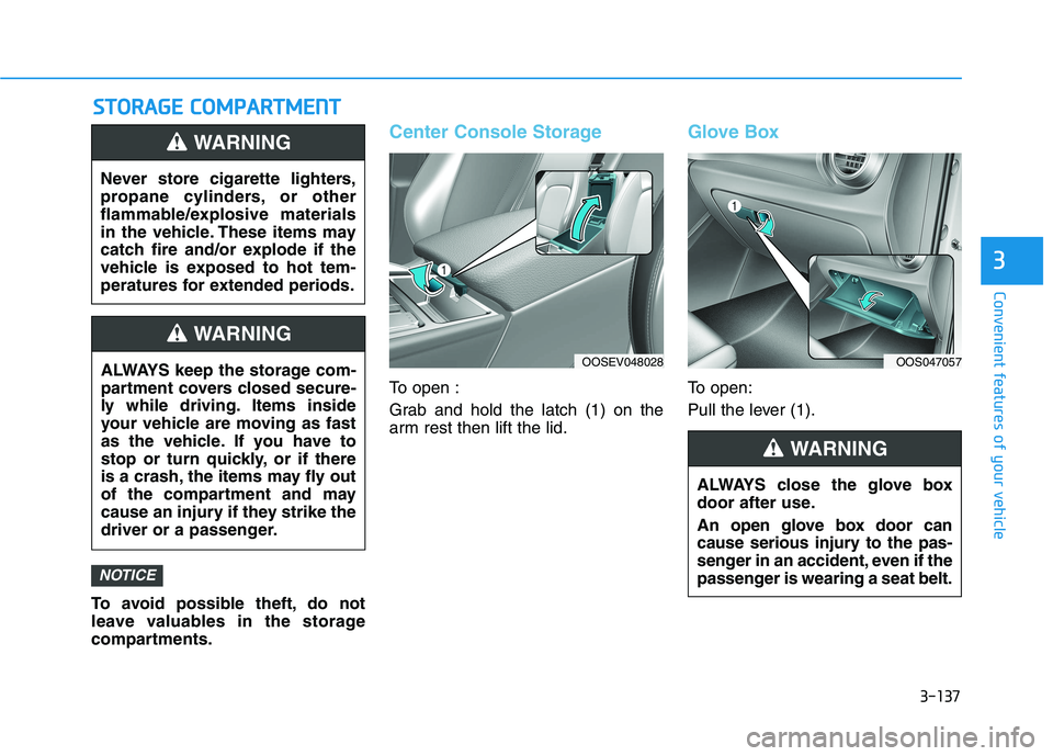
Center Console Storage
To open :
Grab and hold the latch (1) on the
arm rest then lift the lid.
Glove Box
To open:
Pull the lever (1).
NOTICE
Never store cigarette lighters,
propane cylinders, or other
flammable/explosive materials
in the vehicle. These items may
catch fire and/or explode if the
vehicle is exposed to hot tem-
peratures for extended periods.
WARNING
ALWAYS keep the storage com-
partment covers closed secure-
ly while driving. Items inside
your vehicle are moving as fast
as the vehicle. If you have to
stop or turn quickly, or if there
is a crash, the items may fly out
of the compartment and may
cause an injury if they strike the
driver or a passenger.
WARNING
ALWAYS close the glove box
door after use.
An open glove box door can
cause serious injury to the pas-
senger in an accident, even if the
passenger is wearing a seat belt.
WARNING
OOSEV048028OOS047057
Page 397 of 478
7-15
7
Maintenance
C CL
LI
IM
MA
AT
TE
E
C
CO
ON
NT
TR
RO
OL
L
A
AI
IR
R
F
FI
IL
LT
TE
ER
R
Filter Inspection
The climate control air filter should
be replaced according to the
Maintenance Schedule. If the vehi-
cle is operated in severely air-pollut-
ed cities or on dusty rough roads for
a long period, it should be inspected
more frequently and replaced earlier.
When you replace the climate control
air filter, replace it performing the fol-
lowing procedure, and be careful to
avoid damaging other components.
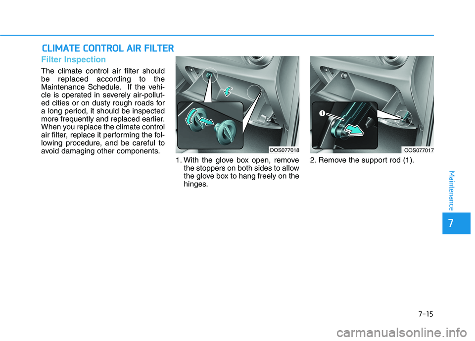
1. With the glove box open, remove
the stoppers on both sides to allow
the glove box to hang freely on the
hinges.2. Remove the support rod (1).
OOS077017OOS077018
Page 427 of 478
7-45
7
Maintenance
Fuse NameFuse RatingProtected Component
INTERIOR
LAMP7.5AGlove Box Lamp, Vanity Lamp LH/RH, Room Lamp, Overhead Console Lamp,
Wiresess Charger Unit, Luggage Lamp
MEMORY 27.5AVess Unit (Speaker), Electronic Refrigerant Reduced Pressure Valve
B/ALARM
HORN10ANot Used
MEMORY 110AA/C Control Module, Head Up Display, Instrument Cluster, BCM, Rain Sensor
SPARE20ASpare
AMP30AAMP
MODULE 67.5ASmart Key Control Module, BCM
MDPS7.5AMDPS Unit
MODULE 17.5AActive Air Flap, Hazard Switch, Data Link Connector, ICM Relay Box (Outside Mirror Folding/Unfolding Relay)
MODULE 77.5AFront Air Ventilation Seat Module, Front Seat Warmer Module
A/BAG IND7.5AInstrument Cluster, A/C Control Module
BRAKE
SWITCH7.5AStop Lamp Switch, Smart Key Control Module
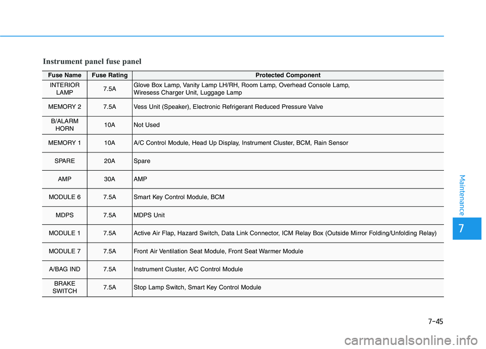
Instrument panel fuse panel