warning Hyundai Matrix 2004 Owner's Manual
[x] Cancel search | Manufacturer: HYUNDAI, Model Year: 2004, Model line: Matrix, Model: Hyundai Matrix 2004Pages: 317, PDF Size: 5.12 MB
Page 215 of 317
1- 33
CONTROLS AND EQUIPMENT
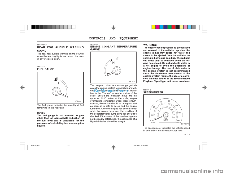
The fuel gauge indicates the quantity of fuel remaining in the fuel tank. NOTE: The fuel gauge is not intended to give other than an approximate indication of the fuel level and is unsuitable for the purposes of calculating fuel consumption figures. SB215B1-E ENGINE COOLANT TEMPERATURE GAUGE The engine coolant temperature gauge indi- cates the engine coolant temperature and will, under normal circumstances, give an indica- tion in the "Normal" or centre portion of the scale. Should the indication move into the upper or "Hot" portion of the scale, engine overheating is indicated. Under these circum- stances, the vehicle should be brought to rest as soon as is safe to do so and the engine turned off. Once the engine has cooled some- what, the coolant level and the condition of the generator/water pump drive belt should be checked. If the cause of the overheating can- not be readily established, the assistance of a Hyundai dealer should be sought.
SB215A1-E FUEL GAUGE
B950A01E-DATREAR FOG AUDIBLE WARNING SOUND The rear fog audible warning chime sounds when the rear fog lights are on and the door in driver side is open.
HFC2101
HFC2045
WARNING: The engine cooling system is pressurizedand removal of the radiator cap when the engine is hot may cause hot water and steam to be ejected from the radiator re- sulting in burns and scalding. The radiator cap must only be removed when the en- gine has cooled. Do not add cold water to a hot engine to avoid the possibility of engine damage. The use of plain water in the cooling system is not recommended since the aluminium components of the cooling system require the use of a corro- sion inhibitor found in the recommended Ethylene Glycol type anti freeze solutions.
B300A01FC
SB215C1-E SPEEDOMETER The speedometer indicates the vehicle speed in both miles and kilometres per hour.
fcuk-1.p65
3/6/2007, 9:58 AM
33
Page 218 of 317
CONTROLS AND EQUIPMENT
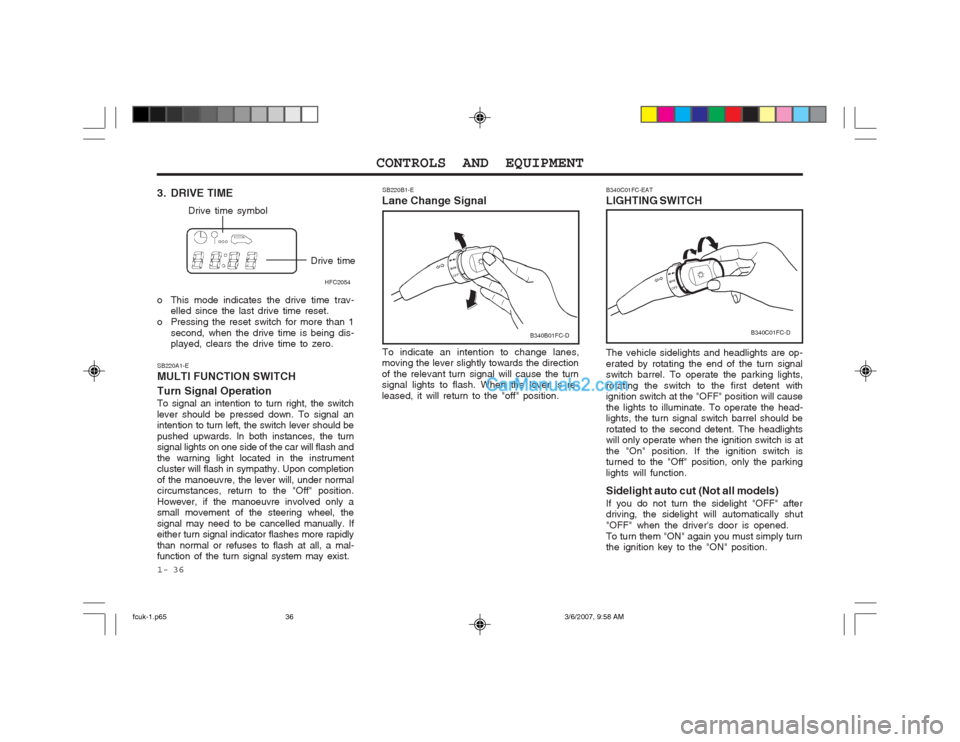
1- 36 The vehicle sidelights and headlights are op- erated by rotating the end of the turn signal switch barrel. To operate the parking lights, rotating the switch to the first detent with ignition switch at the "OFF" position will cause the lights to illuminate. To operate the head- lights, the turn signal switch barrel should be rotated to the second detent. The headlights will only operate when the ignition switch is at the "On" position. If the ignition switch is turned to the "Off" position, only the parking lights will function. Sidelight auto cut (Not all models) If you do not turn the sidelight "OFF" after driving, the sidelight will automatically shut "OFF" when the driver's door is opened.To turn them "ON" again you must simply turn the ignition key to the "ON" position.
B340C01FC-EAT LIGHTING SWITCH
SB220A1-EMULTI FUNCTION SWITCH Turn Signal Operation To signal an intention to turn right, the switch lever should be pressed down. To signal an intention to turn left, the switch lever should be pushed upwards. In both instances, the turn signal lights on one side of the car will flash and the warning light located in the instrument cluster will flash in sympathy. Upon completion of the manoeuvre, the lever will, under normal circumstances, return to the "Off" position. However, if the manoeuvre involved only a small movement of the steering wheel, the signal may need to be cancelled manually. If either turn signal indicator flashes more rapidly than normal or refuses to flash at all, a mal- function of the turn signal system may exist. SB220B1-E
Lane Change Signal
To indicate an intention to change lanes,
moving the lever slightly towards the direction of the relevant turn signal will cause the turn signal lights to flash. When the lever is re- leased, it will return to the "off" position.
3. DRIVE TIME
Drive time symbol
Drive timeHFC2054
o This mode indicates the drive time trav- elled since the last drive time reset.
o Pressing the reset switch for more than 1 second, when the drive time is being dis- played, clears the drive time to zero. B340C01FC-D
B340B01FC-D
fcuk-1.p65
3/6/2007, 9:58 AM
36
Page 220 of 317
CONTROLS AND EQUIPMENT
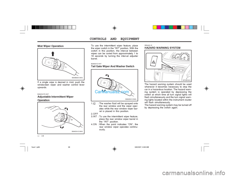
1- 38 SB240A1-E HAZARD WARNING SYSTEM The hazard warning system should be used whenever it becomes necessary to stop the car in a hazardous location. The hazard warn- ing system is operated by depressing the switch at which time all turn signal lights will flash simultaneously and the turn signal warn- ing lights located within the instrument cluster will flash simultaneously. The hazard warning system may be turned off by depressing the switch again.
B350C01FC-DAT Adjustable Intermittent Wiper Operation To use the intermittent wiper feature, place the wiper switch in the "INT" position. With the switch in this position, the interval between wipes can be varied from approximately 1 to 18 seconds by turning the interval adjuster barrel.
Mist Wiper Operation If a single wipe is desired in mist, push the windscreen wiper and washer control lever upwards. B350A01O-AAT Tail Gate Wiper And Washer Switch
1. : The washer fluid will be sprayed onto
the rear window and the wiper oper- ates while the rear window wiper bar- rel is placed in this position.
2.OFF
3.INT : To use the intermittent wiper feature,
place the rear window wiper barrel inthe "INT" position.
4.ON : When the point indicates "ON", the rear window wiper operates continu- ously.
B350B02O-DAG
B350C01O-DAG
B350D01O-DAG
HFC2078-D
fcuk-1.p65 3/6/2007, 9:58 AM
38
Page 223 of 317
1- 41
CONTROLS AND EQUIPMENT
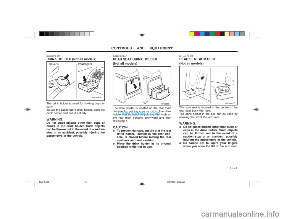
The drink holder is used for holding cups or cans. To use the passenger's drink holder, push thedrink holder and pull it entirely. WARNING: Do not place objects other than cups or drinks in the drink holder. Such objects can be thrown out in the event of a sudden stop or an accident, possibly injuring the passengers in the vehicle.
B450A01FC-EAT DRINK HOLDER (Not all models)
B450B01FC-EAT REAR SEAT DRINK HOLDER (Not all models) The drink holder is located on the rear main console for holding cups or cans. The drink holder can be used by pushing the knob on the rear main console downward and then releasing it. CAUTION:
o To prevent damage, ensure that the rear
drink holder, located in the rear con-sole, is closed before folding the rear seatback and seat cushion.
o Place the drink holder in its original position while not in use.
HFC2097-D
Driver's Passenger's
HFC2098
B611A01FC-EAT REAR SEAT ARM REST (Not all models) This arm rest is located in the centre of the rear seat back with box. The drink holder in the box can be used byopening the lid of the arm rest. WARNING:
o Do not place objects other than cups or
cans in the drink holder. Such objects can be thrown out in the event of a sudden stop or an accident, possibly injuring the passengers in the vehicle.
o Be careful not to injure your fingers
when you open the lid of the arm rest.
B610A01FC
fcuk-1.p65 3/6/2007, 9:58 AM
41
Page 225 of 317
1- 43
CONTROLS AND EQUIPMENT
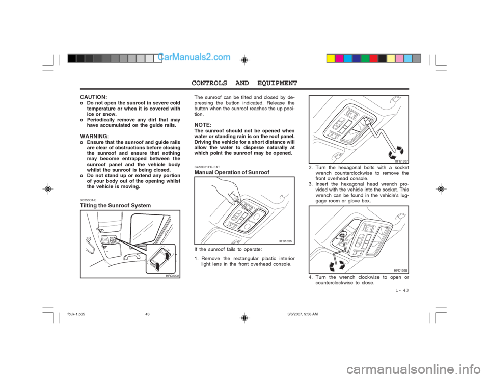
SB330C1-E Tilting the Sunroof System The sunroof can be tilted and closed by de- pressing the button indicated. Release the button when the sunroof reaches the up posi- tion. NOTE: The sunroof should not be opened when water or standing rain is on the roof panel. Driving the vehicle for a short distance will allow the water to disperse naturally at which point the sunroof may be opened.
2. Turn the hexagonal bolts with a socketwrench counterclockwise to remove the front overhead console.
3. Insert the hexagonal head wrench pro- vided with the vehicle into the socket. This wrench can be found in the vehicle's lug- gage room or glove box.
B460D01FC-EAT Manual Operation of Sunroof
HFC1036
If the sunroof fails to operate:
1. Remove the rectangular plastic interior light lens in the front overhead console.
HFC1037
4. Turn the wrench clockwise to open or counterclockwise to close.
CAUTION:
o Do not open the sunroof in severe cold
temperature or when it is covered with ice or snow.
o Periodically remove any dirt that may have accumulated on the guide rails.
WARNING:
o Ensure that the sunroof and guide rails are clear of obstructions before closingthe sunroof and ensure that nothing may become entrapped between the sunroof panel and the vehicle body whilst the sunroof is being closed.
o Do not stand up or extend any portion of your body out of the opening whilstthe vehicle is moving.
HFC2022HFC1038
fcuk-1.p65 3/6/2007, 9:58 AM
43
Page 226 of 317
CONTROLS AND EQUIPMENT
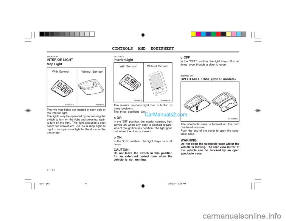
1- 44 The interior courtesy light has a button of three positions. The three positions are:
oDR In the "DR" position, the interior courtesy light comes on when any door is opened regard- less of the ignition key position. The light goes out when the door is closed.
oON In the "ON" position, the light stays on at all times. CAUTION: Do not leave the switch in this position for an extended period time when the vehicle is not running.
SB340B2-E Interior Light
B490A01E
With Sunroof
Without Sunroof
B490B01E
B491A02F-EAT SPECTACLE CASE (Not all models)
HXDOM241
The spectacle case is located on the front overhead console. Push the end of the cover to open the spec-tacle case. WARNING: Do not open the spectacle case whilst the vehicle is moving. The rear view mirror of the vehicle can be blocked by an open spectacle case.
B480A01E-EAT INTERIOR LIGHT Map Light The two map lights are located at each side of the interior light. The lights may be operated by depressing theswitch to turn on the light and pressing again to turn off the light. This light produces a spot beam for convenient use as a map light at night or as a personal light for the driver or the passenger.
B480A01EB480B01E
With Sunroof Without Sunroof
o OFF In the "OFF" position, the light stays off at all times even though a door is open.
fcuk-1.p65 3/6/2007, 9:58 AM
44
Page 227 of 317
1- 45
CONTROLS AND EQUIPMENT
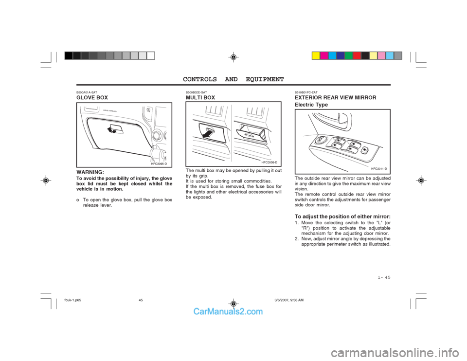
B500A01A-EAT GLOVE BOX WARNING: To avoid the possibility of injury, the glove box lid must be kept closed whilst the vehicle is in motion.
o To open the glove box, pull the glove box release lever. The multi box may be opened by pulling it out by its grip. It is used for storing small commodities. If the multi box is removed, the fuse box forthe lights and other electrical accessories will be exposed.
B500B02E-GAT MULTI BOX
HFC2095-DHFC2058-D
HFC2011-D
B510B01FC-EAT EXTERIOR REAR VIEW MIRROR Electric Type The outside rear view mirror can be adjusted in any direction to give the maximum rear view vision. The remote control outside rear view mirrorswitch controls the adjustments for passenger side door mirror. To adjust the position of either mirror:
1. Move the selecting switch to the "L" (or
"R") position to activate the adjustable mechanism for the adjusting door mirror.
2. Now, adjust mirror angle by depressing the appropriate perimeter switch as illustrated.
fcuk-1.p65 3/6/2007, 9:58 AM
45
Page 228 of 317
CONTROLS AND EQUIPMENT
1- 46
SB360C1-F
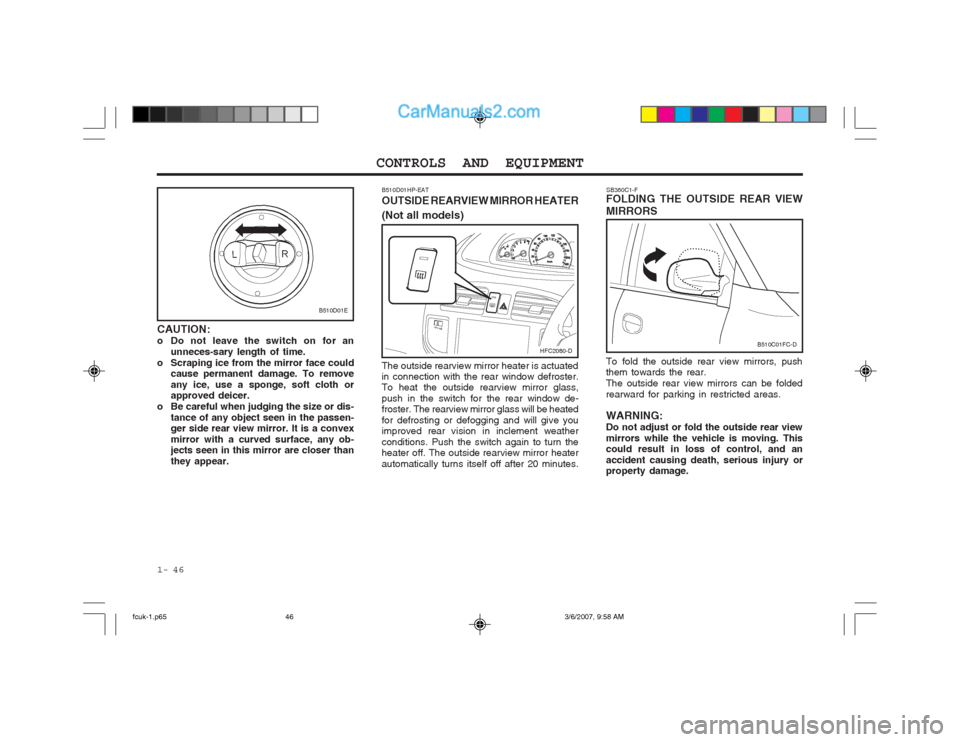
FOLDING THE OUTSIDE REAR VIEW MIRRORS To fold the outside rear view mirrors, push them towards the rear. The outside rear view mirrors can be foldedrearward for parking in restricted areas. WARNING: Do not adjust or fold the outside rear viewmirrors while the vehicle is moving. This could result in loss of control, and an accident causing death, serious injury or property damage.
B510D01E
CAUTION:
o Do not leave the switch on for an unneces-sary length of time.
o Scraping ice from the mirror face could cause permanent damage. To removeany ice, use a sponge, soft cloth or approved deicer.
o Be careful when judging the size or dis- tance of any object seen in the passen-ger side rear view mirror. It is a convex mirror with a curved surface, any ob- jects seen in this mirror are closer than they appear.
B510C01FC-D
B510D01HP-EAT OUTSIDE REARVIEW MIRROR HEATER (Not all models)
The outside rearview mirror heater is actuated in connection with the rear window defroster.To heat the outside rearview mirror glass, push in the switch for the rear window de- froster. The rearview mirror glass will be heated for defrosting or defogging and will give you improved rear vision in inclement weather conditions. Push the switch again to turn the heater off. The outside rearview mirror heater automatically turns itself off after 20 minutes. HFC2080-D
fcuk-1.p65
3/6/2007, 9:58 AM
46
Page 229 of 317
1- 47
CONTROLS AND EQUIPMENT
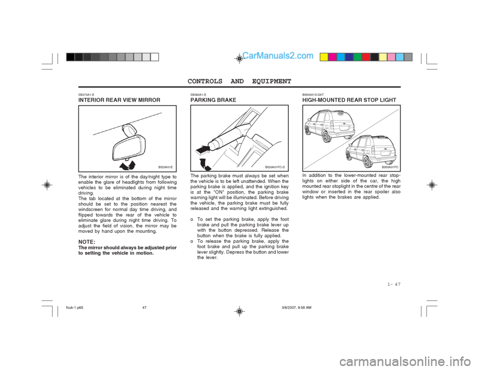
SB380A1-E PARKING BRAKE The parking brake must always be set when the vehicle is to be left unattended. When the parking brake is applied, and the ignition key is at the "ON" position, the parking brake warning light will be illuminated. Before driving the vehicle, the parking brake must be fully released and the warning light extinguished.
o To set the parking brake, apply the foot brake and pull the parking brake lever up with the button depressed. Release the button when the brake is fully applied.
o To release the parking brake, apply the foot brake and pull up the parking brakelever slightly. Depress the button and lower the lever.
SB370A1-E INTERIOR REAR VIEW MIRROR The interior mirror is of the day/night type to enable the glare of headlights from following vehicles to be eliminated during night time driving. The tab located at the bottom of the mirrorshould be set to the position nearest the windscreen for normal day time driving, and flipped towards the rear of the vehicle to eliminate glare during night time driving. To adjust the field of vision, the mirror may be moved by hand upon the mounting. NOTE: The mirror should always be adjusted prior to setting the vehicle in motion.
B530A01FC-DB550A01FC
B520A01E
B550A01S-DAT HIGH-MOUNTED REAR STOP LIGHT In addition to the lower-mounted rear stop-
lights on either side of the car, the high mounted rear stoplight in the centre of the rear window or inserted in the rear spoiler also
lights when the brakes are applied.
fcuk-1.p65 3/6/2007, 9:58 AM
47
Page 230 of 317

CONTROLS AND EQUIPMENT
1- 48 B820A01FC-GAT ACCESSORY TRAY
HFC2071-D
B500D07O-EAT
POWER OUTLET (Not all models)
HFC2042-D
These supply 12V electric power to operate electric accessories or equipment only when the key is in the "ON" or "ACC" position. CAUTION: Do not use electric accessories or equip- ment other than the Hyundai genuine parts in the socket.
The accessory tray may be opened by push-ing the knob sidewards and releasing slowly it.It is used for storing small commodities.
B810A01FC-GAT FOLD-UP TRAY
For your convenience, it may be used as a table holding a book, cup or can. WARNING: To avoid the possibility of injury in case ofan accident or a sudden stop, the fold-up tray should be place its original position while the vehicle is moving.
HFC2070
fcuk-1.p65
3/6/2007, 9:58 AM
48