audio Hyundai Matrix 2004 User Guide
[x] Cancel search | Manufacturer: HYUNDAI, Model Year: 2004, Model line: Matrix, Model: Hyundai Matrix 2004Pages: 317, PDF Size: 5.12 MB
Page 162 of 317
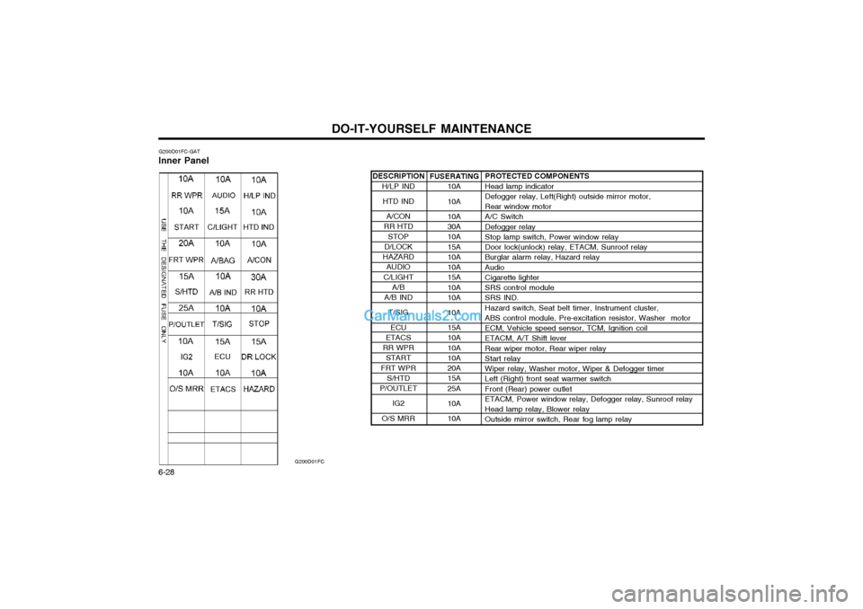
DO-IT-YOURSELF MAINTENANCE
6-28 DESCRIPTION
H/LP IND
HTD IND
A/CON
RR HTD
STOP
D/LOCK
HAZARD AUDIO
C/LIGHT A/B
A/B IND
T/SIG
ECU
ETACS
RR WPR START
FRT WPR S/HTD
P/OUTLET
IG2
O/S MRR
G200D01FC-GAT
Inner Panel
G200D01FC
PROTECTED COMPONENTS Head lamp indicator Defogger relay, Left(Right) outside mirror motor, Rear window motor A/C Switch Defogger relay Stop lamp switch, Power window relay Door lock(unlock) relay, ETACM, Sunroof relay Burglar alarm relay, Hazard relay Audio Cigarette lighter SRS control module SRS IND. Hazard switch, Seat belt timer, Instrument cluster, ABS control module, Pre-excitation resistor, Washer motor ECM, Vehicle speed sensor, TCM, Ignition coil ETACM, A/T Shift lever Rear wiper motor, Rear wiper relay Start relay Wiper relay, Washer motor, Wiper & Defogger timer Left (Right) front seat warmer switch Front (Rear) power outlet ETACM, Power window relay, Defogger relay, Sunroof relay Head lamp relay, Blower relay Outside mirror switch, Rear fog lamp relay
FUSERATING
10A 10A 10A 30A 10A 15A 10A 10A 15A 10A 10A 10A 15A 10A 10A 10A 20A 15A 25A 10A 10A
Page 242 of 317
CONTROLS AND EQUIPMENT
1- 60
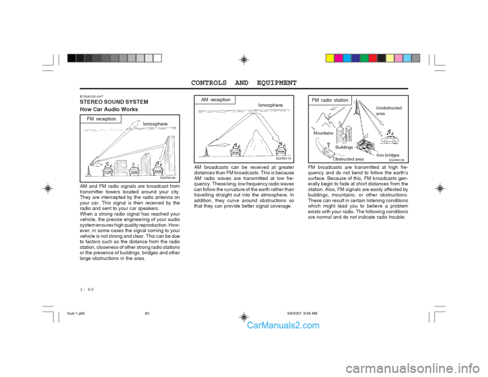
FM broadcasts are transmitted at high fre- quency and do not bend to follow the earth's surface. Because of this, FM broadcasts gen- erally begin to fade at short distances from the station. Also, FM signals are easily affected by buildings, mountains, or other obstructions. These can result in certain listening conditions which might lead you to believe a problem exists with your radio. The following conditions are normal and do not indicate radio trouble:
Buildings
Obstructed area
Unobstructed area
FM radio station
SSAR012A
Mountains
Iron bridges
B750A02A-AAT STEREO SOUND SYSTEM How Car Audio Works
IonosphereFM reception
SSAR010A
AM and FM radio signals are broadcast from transmitter towers located around your city. They are intercepted by the radio antenna on your car. This signal is then received by the radio and sent to your car speakers. When a strong radio signal has reached your vehicle, the precise engineering of your audio system ensures high quality reproduction. How- ever, in some cases the signal coming to your vehicle is not strong and clear. This can be due to factors such as the distance from the radio station, closeness of other strong radio stations or the presence of buildings, bridges and other large obstructions in the area.
Ionosphere
SSAR011A
AM reception
AM broadcasts can be received at greater distances than FM broadcasts. This is because AM radio waves are transmitted at low fre- quency. These long, low frequency radio waves can follow the curvature of the earth rather than travelling straight out into the atmosphere. In addition, they curve around obstructions so that they can provide better signal coverage.
fcuk-1.p65 3/6/2007, 9:58 AM
60
Page 243 of 317
1- 61
CONTROLS AND EQUIPMENT
B750B02Y-AAT Using a cellular phone or a two-way radio When a cellular phone is used inside the vehicle, noise may be produced from the audio equipment. This does not mean that something is wrong with the audio equipment. In such a case, use the cellular phone at a place as far as possible from the audio equip- ment. CAUTION: When using a communication system suchas a cellular phone or a radio inside the vehicle, a separate external antenna must be fitted.When a cellular phone or a radio set is used with an internal antenna alone, it may interfere with the vehicle's electrical sys- tem and adversely affect safe operation of the vehicle. WARNING: Don't use a cellular phone when you are driving, you must stop at a safe place to use a cellular phone.
SSAR014A
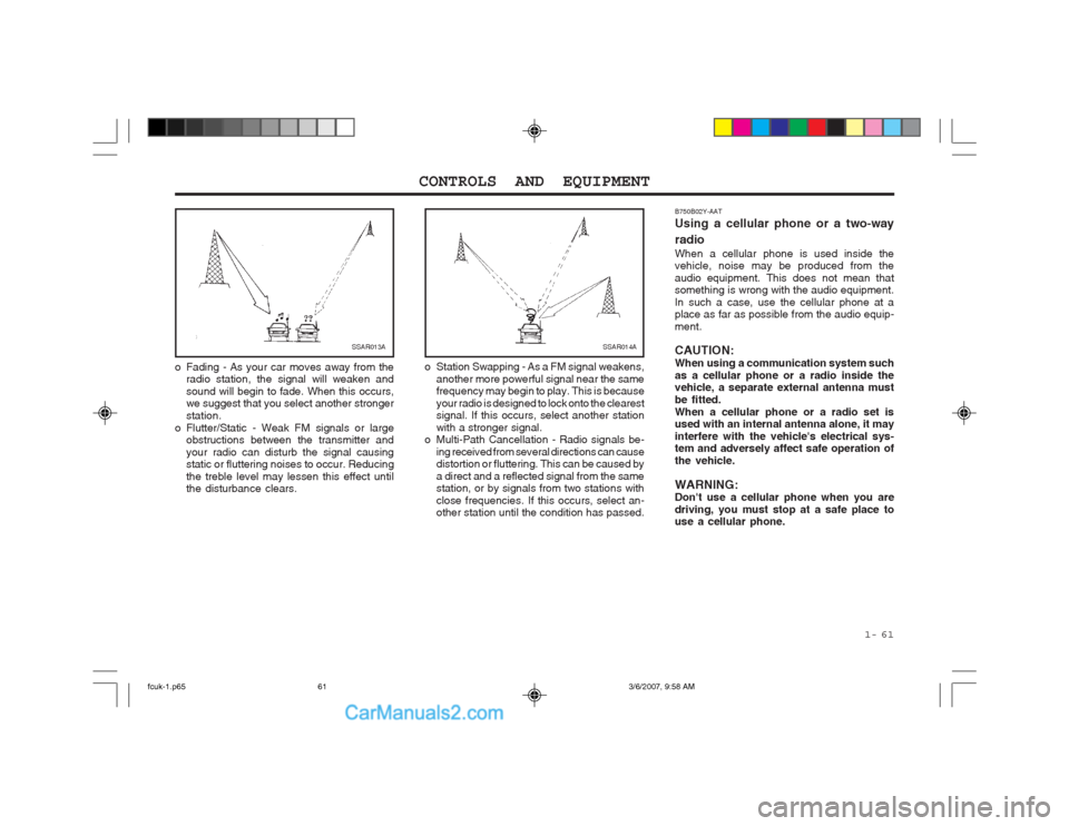
o Station Swapping - As a FM signal weakens, another more powerful signal near the same frequency may begin to play. This is because your radio is designed to lock onto the clearest signal. If this occurs, select another station with a stronger signal.
o Multi-Path Cancellation - Radio signals be-
ing received from several directions can cause distortion or fluttering. This can be caused by a direct and a reflected signal from the same station, or by signals from two stations with close frequencies. If this occurs, select an- other station until the condition has passed.SSAR013A
o Fading - As your car moves away from the radio station, the signal will weaken and sound will begin to fade. When this occurs, we suggest that you select another stronger station.
o Flutter/Static - Weak FM signals or large obstructions between the transmitter andyour radio can disturb the signal causing static or fluttering noises to occur. Reducing the treble level may lessen this effect until the disturbance clears.
fcuk-1.p65 3/6/2007, 9:58 AM
61
Page 303 of 317
OWNER MAINTENANCE 6-25
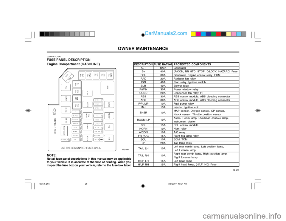
G200C01FC-GAT
FUSE PANEL DESCRIPTION Engine Compartment (GASOLINE)
HFC4004PROTECTED COMPONENTS Generator (A/CON, RR HTD, STOP, D/LOCK, HAZARD) Fuse Generator, Engine control relay, ECM Radiator fan relay Start relay, Ignition switch Blower relay Power window relay Condenser fan relay #1 ABS control module, ABS bleeding connector ABS control module, ABS bleeding connector Fuel pump relay Injector, lgnition coil MAP sensor, Oxygen sensor, CP sensor, Knock sensor, Throttle position sensor Audio, Room lamp, Overhead console lamp, lnstrument cluster DRL control module Horn relay A/C relay Front fog lamp relay ECM, TCM Tail lamp relay Left rear combi lamp, Left position lamp, Left License lamp Right rear combi lamp, Right position lamp, Right License lamp Left head lamp Right head lamp, (H/LP IND) Fuse
FUSE RATING
120A40A 30A 20A 40A 40A 30A 20A 30A 30A 10A 15A 10A 10A 15A 10A 10A 15A 10A 20A 10A 10A 15A 15A
DESCRIPTION
ALTB+
ECU RAD IGN
BLR
P/WIN
COND
ABSABS
F/PUMP INJ
SNSR
ROOM LP DRL
HORN
A/CON
FR FOG
ECULP
TAIL LH
TAIL RH H/LP LH
H/LP RH
NOTE: Not all fuse panel descriptions in this manual may be applicable
to your vehicle. It is accurate at the time of printing. When you inspect the fuse box on your vehicle, refer to the fuse box label.
fcuk-6.p65 3/6/2007, 10:01 AM
25
Page 304 of 317
OWNER MAINTENANCE
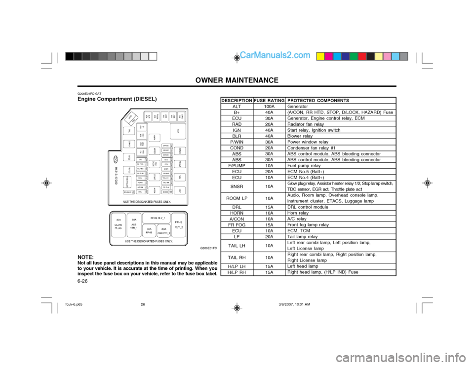
6-26 DESCRIPTION
ALTB+
ECU RAD IGN
BLR
P/WIN
COND
ABSABS
F/PUMP ECU ECU
SNSR
ROOM LP DRL
HORN
A/CON
FR FOG
ECULP
TAIL LH
TAIL RH H/LP LH
H/LP RH
G200E01FC-GAT Engine Compartment (DIESEL)
G200E01FCPROTECTED COMPONENTS Generator (A/CON, RR HTD, STOP, D/LOCK, HAZARD) Fuse Generator, Engine control relay, ECM Radiator fan relay Start relay, Ignition switch Blower relay Power window relay Condenser fan relay #1 ABS control module, ABS bleeding connector ABS control module, ABS bleeding connector Fuel pump relay ECM No.5 (Batt+) ECM No.4 (Batt+)
Glow plug r elay, Assistor heater r elay 1/2, Stop lamp switch,
TDC sensor, EGR act, Throttle plate a c t Audio, Room lamp, Overhead console lamp, lnstrument cluster, ETACS, Luggage lamp DRL control module Horn relay A/C relay Front fog lamp relay ECM, TCM Tail lamp relay Left rear combi lamp, Left position lamp, Left License lamp Right rear combi lamp, Right position lamp, Right License lamp Left head lamp Right head lamp, (H/LP IND) Fuse
FUSE RATING
100A40A 30A 20A 40A 40A 30A 20A 30A 30A 10A 20A 10A 10A 10A 15A 10A 10A 15A 10A 20A 10A 10A 15A 15A
NOTE: Not all fuse panel descriptions in this manual may be applicable to your vehicle. It is accurate at the time of printing. When youinspect the fuse box on your vehicle, refer to the fuse box label.
fcuk-6.p65 3/6/2007, 10:01 AM
26
Page 305 of 317
OWNER MAINTENANCE 6-27
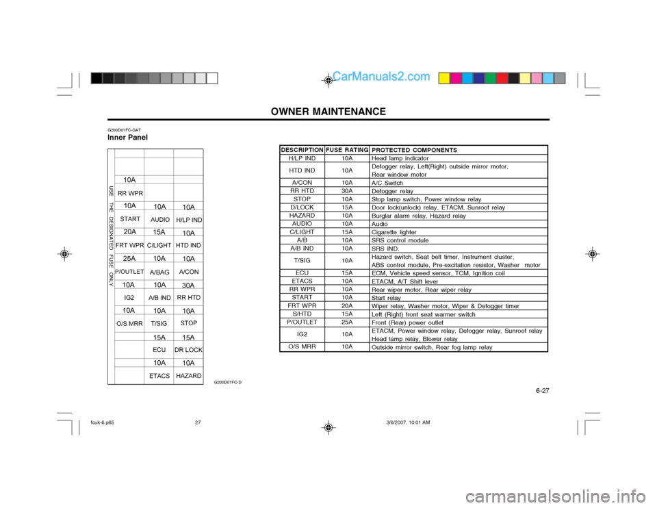
DESCRIPTION
H/LP IND
HTD IND
A/CON
RR HTD
STOP
D/LOCK
HAZARD AUDIO
C/LIGHT A/B
A/B IND
T/SIG
ECU
ETACS
RR WPR START
FRT WPR S/HTD
P/OUTLET
IG2
O/S MRR
G200D01FC-GAT
Inner Panel
G200D01FC-D
PROTECTED COMPONENTS Head lamp indicator Defogger relay, Left(Right) outside mirror motor, Rear window motor A/C Switch Defogger relay Stop lamp switch, Power window relay Door lock(unlock) relay, ETACM, Sunroof relay Burglar alarm relay, Hazard relay Audio Cigarette lighter SRS control module SRS IND. Hazard switch, Seat belt timer, Instrument cluster, ABS control module, Pre-excitation resistor, Washer motor ECM, Vehicle speed sensor, TCM, Ignition coil ETACM, A/T Shift lever Rear wiper motor, Rear wiper relay Start relay Wiper relay, Washer motor, Wiper & Defogger timer Left (Right) front seat warmer switch Front (Rear) power outlet ETACM, Power window relay, Defogger relay, Sunroof relay Head lamp relay, Blower relay Outside mirror switch, Rear fog lamp relay
FUSE RATING
10A 10A 10A 30A 10A 15A 10A 10A 15A 10A 10A 10A 15A 10A 10A 10A 20A 15A 25A 10A 10A
fcuk-6.p65 3/6/2007, 10:01 AM
27