computer Hyundai Matrix 2004 Owner's Manual
[x] Cancel search | Manufacturer: HYUNDAI, Model Year: 2004, Model line: Matrix, Model: Hyundai Matrix 2004Pages: 317, PDF Size: 5.12 MB
Page 39 of 317
FEATURES OF YOUR HYUNDAI 1- 31
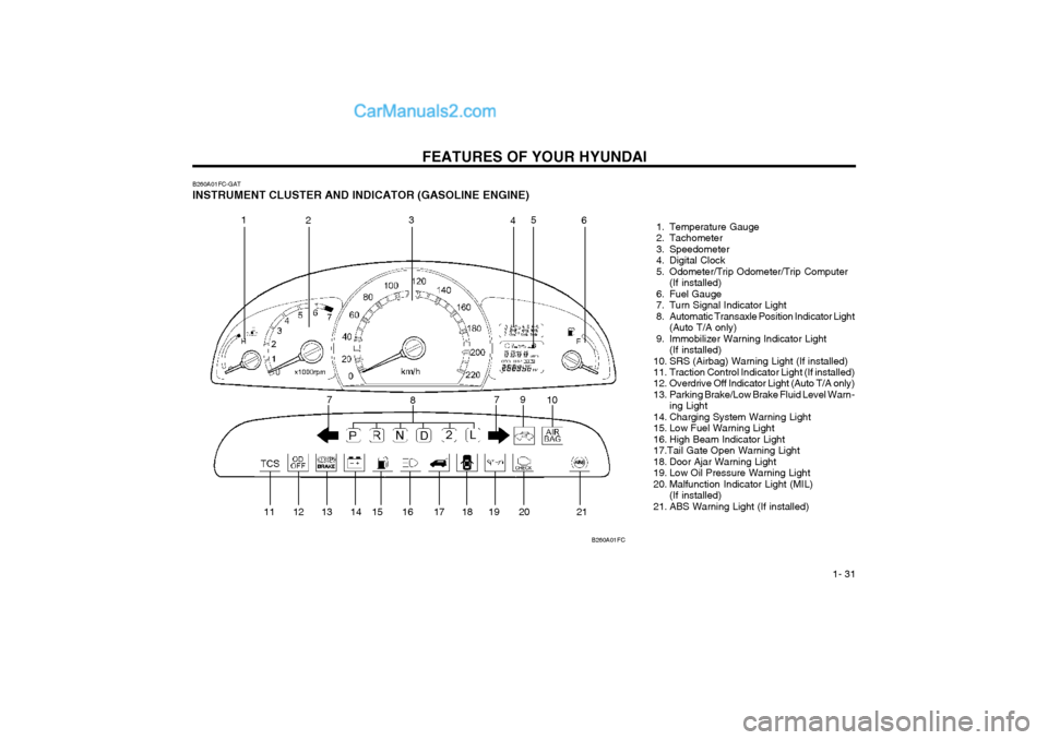
B260A01FC-GAT INSTRUMENT CLUSTER AND INDICATOR (GASOLINE ENGINE) 1. Temperature Gauge
2. Tachometer
3. Speedometer
4. Digital Clock
5. Odometer/Trip Odometer/Trip Computer(If installed)
6. Fuel Gauge
7. Turn Signal Indicator Light
8. Automatic Transaxle Position Indicator Light (Auto T/A only)
9. Immobilizer Warning Indicator Light (If installed)
10. SRS (Airbag) Warning Light (If installed)
11. Traction Control Indicator Light (If installed)
12. Overdrive Off Indicator Light (Auto T/A only)
13. Parking Brake/Low Brake Fluid Level Warn- ing Light
14. Charging System Warning Light
15. Low Fuel Warning Light
16. High Beam Indicator Light17.Tail Gate Open Warning Light
18. Door Ajar Warning Light
19. Low Oil Pressure Warning Light
20. Malfunction Indicator Light (MIL) (If installed)
21. ABS Warning Light (If installed)
B260A01FC
1
2 3
45
6
7 8 9
10
11 12 13 14 15 16 17 18 19 20 21 7
Page 40 of 317
FEATURES OF YOUR HYUNDAI
1- 32
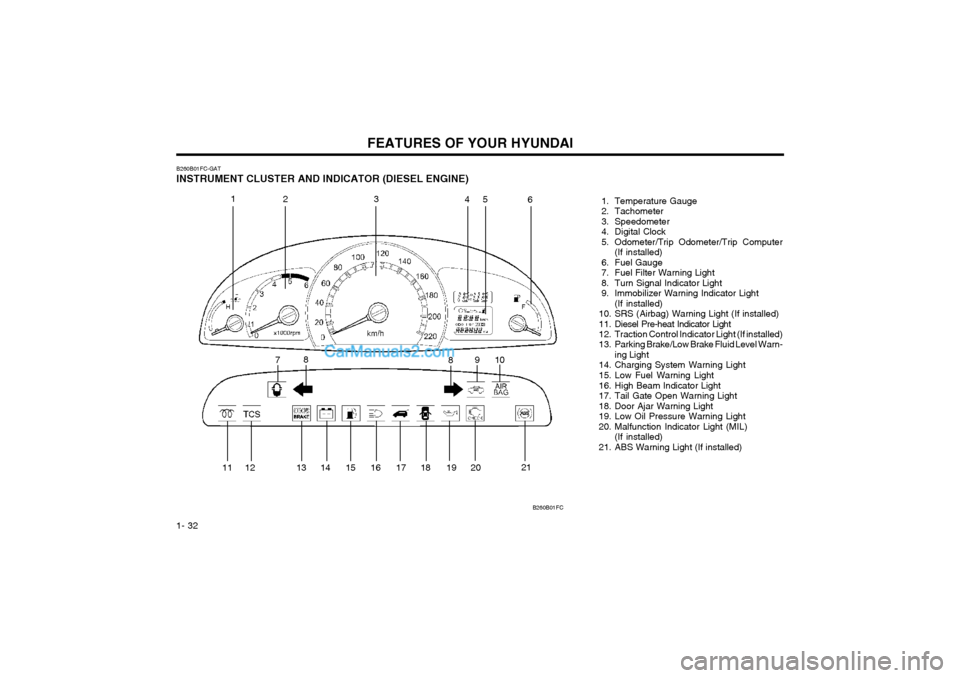
B260B01FC-GAT INSTRUMENT CLUSTER AND INDICATOR (DIESEL ENGINE)
1. Temperature Gauge
2. Tachometer
3. Speedometer
4. Digital Clock
5. Odometer/Trip Odometer/Trip Computer(If installed)
6. Fuel Gauge
7. Fuel Filter Warning Light
8. Turn Signal Indicator Light
9. Immobilizer Warning Indicator Light (If installed)
10. SRS (Airbag) Warning Light (If installed)
11. Diesel Pre-heat Indicator Light
12. Traction Control Indicator Light (If installed)
13. Parking Brake/Low Brake Fluid Level Warn- ing Light
14. Charging System Warning Light
15. Low Fuel Warning Light
16. High Beam Indicator Light
17. Tail Gate Open Warning Light
18. Door Ajar Warning Light
19. Low Oil Pressure Warning Light
20. Malfunction Indicator Light (MIL) (If installed)
21. ABS Warning Light (If installed)
B260B01FC
1 23 45
6
7 8
910
8
11 12 13 14 15 16 17 18 19 20 21
Page 45 of 317
FEATURES OF YOUR HYUNDAI 1- 37
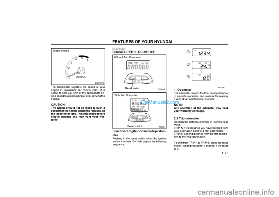
The tachometer registers the speed of your engine in revolutions per minute (rpm). It isuseful to help you shift at the appropriate en-gine speed to avoid lugging or over-revving theengine. CAUTION: The engine should not be raced to such aspeed that the needle enters the red zone onthe tachometer face. This can cause severeengine damage and may void your war-ranty.
B310B01FC-GAT ODOMETER/TRIP ODOMETER
HFC2089
Function of digital odometer/trip odom- eter
Pushing in the reset switch when the ignition switch is turned "ON" will display the followingsequence:Reset switch
HFC2051Reset switch
Without Trip Computer
With Trip Computer 1. Odometer The odometer records the total driving distance in kilometers or miles, and is useful for keepinga record for maintenance intervals. NOTE: Any alteration of the odometer may voidyour warranty coverage. 2,3 Trip odometer Records the distance of 2 trips in kilometers or miles.TRIP A:
First distance you have traveled from
your origination point to a first destination.TRIP B: Second distance from the first destina-
tion to the final destination. To shift from TRIP A to TRIP B, press the reset switch. When pressed for 1 second, it will resetto 0.
HFC2090
B330A01FC
Diesel engine
Page 46 of 317
FEATURES OF YOUR HYUNDAI
1- 38
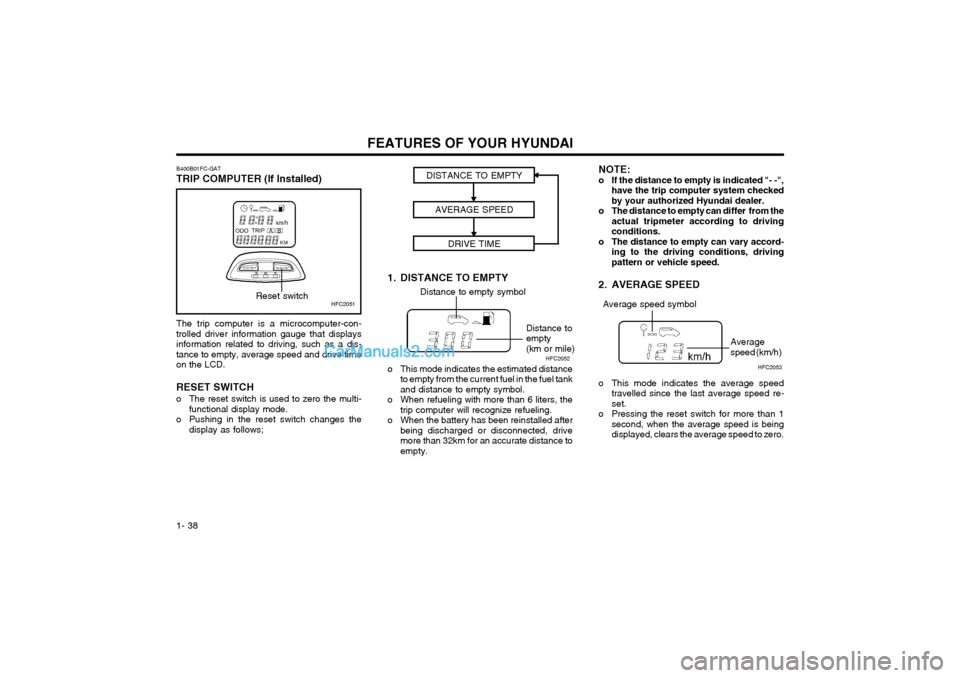
The trip computer is a microcomputer-con- trolled driver information gauge that displaysinformation related to driving, such as a dis-tance to empty, average speed and drive timeon the LCD. RESET SWITCH
o The reset switch is used to zero the multi-
functional display mode.
o Pushing in the reset switch changes the display as follows;
HFC2051
B400B01FC-GAT TRIP COMPUTER (If Installed)Reset switch
1. DISTANCE TO EMPTYDISTANCE TO EMPTY
AVERAGE SPEED DRIVE TIMEDistance to empty symbol
Distance to empty(km or mile)
o This mode indicates the estimated distance to empty from the current fuel in the fuel tankand distance to empty symbol.
o When refueling with more than 6 liters, the trip computer will recognize refueling.
o When the battery has been reinstalled after being discharged or disconnected, drivemore than 32km for an accurate distance toempty. NOTE:
o If the distance to empty is indicated "- -",
have the trip computer system checkedby your authorized Hyundai dealer.
o The distance to empty can differ from the actual tripmeter according to drivingconditions.
o The distance to empty can vary accord- ing to the driving conditions, drivingpattern or vehicle speed.
2. AVERAGE SPEED
o This mode indicates the average speed travelled since the last average speed re- set.
o Pressing the reset switch for more than 1 second, when the average speed is beingdisplayed, clears the average speed to zero.
Average speed symbol
Average speed (km/h)
HFC2052
HFC2053
Page 174 of 317
INDEX
10-4 Sunroof
................................................................................... 1-45 ~ 1-46
Sunshade .......................................................................................... 1-45
Sun Visor .......................................................................................... 1-55
T
Tail Gate ........................................................................................... 1-52
Tail Gate Wiper And Washer Switch ................................................1-41
Tachometer ............................................................................ 1-36 ~ 1-37
Theft Alarm System ................................................................... 1-6 ~ 1-7
Tires Balancing ......................................................................................... 8-3
Chains ............................................................................................. 8-2
Changing a flat tire .......................................................................... 3-4
If you have a flat tire ....................................................................... 3-4
Information ....................................................................................... 8-1
Pressure .......................................................................................... 8-1
Replacement ................................................................................... 8-3
Rotation ........................................................................................... 8-2
Snow tires ....................................................................................... 8-2
Spare tire ......................................................................................... 3-4 Traction ........................................................................................... 8-3
Towing A trailer (or vehicle) ...................................................................... 2-12
Emergency ...................................................................................... 3-9
If your car must be towed ............................................................... 3-8
Transaxle Automatic ............................................................................... 2-5 ~ 2-8
Automatic transaxle fluid checking .................................... 6-13 ~ 6-14
Manual ....................................................................................... 2-4 ~ 2-5
Manual transaxle oil checking .................... ...................................6-13
Trip Computer ............................... ......................................... 1-38 ~ 1-39
Trip Odometer ................................................................................... 1-37U
Under Tray ........................................................................................
1-10
VVehicle Identificati on Number (VIN) .................................................... 8-1
Vehicle Specification ........................................................................... 9-1Ventilation Center ventilator ............................................................................ 1-56
Side ventilator ............................................................................... 1-56
W
Warning Lights ....................................................................... 1-33 ~ 1-35
Windows Manual ............................................................................................. 1-8
Power .............................................................................................. 1-8
Windshield Wiper and Washer Switch ..............................................1-40
Windshield Wiper Blades .................................................................. 6-12
Page 210 of 317
CONTROLS AND EQUIPMENT
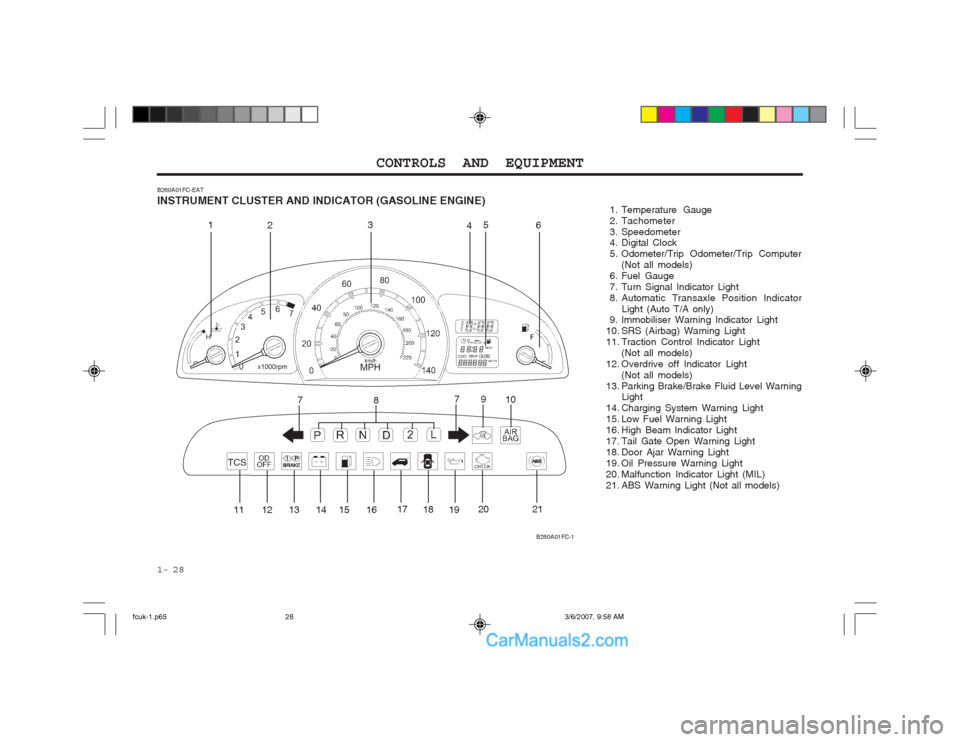
1- 28
B260A01FC-EAT INSTRUMENT CLUSTER AND INDICATOR (GASOLINE ENGINE) 1. Temperature Gauge
2. Tachometer
3. Speedometer
4. Digital Clock
5. Odometer/Trip Odometer/Trip Computer
(Not all models)
6. Fuel Gauge
7. Turn Signal Indicator Light
8. Automatic Transaxle Position Indicator Light (Auto T/A only)
9. Immobiliser Warning Indicator Light
10. SRS (Airbag) Warning Light
11. Traction Control Indicator Light
(Not all models)
12. Overdrive off Indicator Light (Not all models)
13. Parking Brake/Brake Fluid Level Warning Light
14. Charging System Warning Light
15. Low Fuel Warning Light
16. High Beam Indicator Light
17. Tail Gate Open Warning Light
18. Door Ajar Warning Light
19. Oil Pressure Warning Light
20. Malfunction Indicator Light (MIL)
21. ABS Warning Light (Not all models)
B260A01FC-1
1
2 3
45
6
7 8 9
10
11 12 13 14 15 16 17
1819 20 21
7
fcuk-1.p65
3/6/2007, 9:58 AM
28
Page 211 of 317
1- 29
CONTROLS AND EQUIPMENT
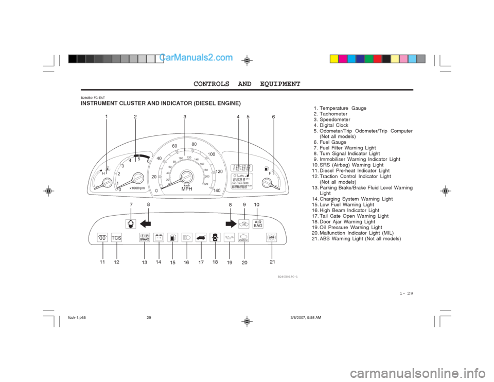
B260B01FC-EAT INSTRUMENT CLUSTER AND INDICATOR (DIESEL ENGINE)
1. Temperature Gauge
2. Tachometer
3. Speedometer
4. Digital Clock
5. Odometer/Trip Odometer/Trip Computer
(Not all models)
6. Fuel Gauge
7. Fuel Filter Warning Light
8. Turn Signal Indicator Light
9. Immobiliser Warning Indicator Light
10. SRS (Airbag) Warning Light
11. Diesel Pre-heat Indicator Light
12. Traction Control Indicator Light (Not all models)
13. Parking Brake/Brake Fluid Level Warning Light
14. Charging System Warning Light
15. Low Fuel Warning Light
16. High Beam Indicator Light
17. Tail Gate Open Warning Light
18. Door Ajar Warning Light
19. Oil Pressure Warning Light
20. Malfunction Indicator Light (MIL)
21. ABS Warning Light (Not all models)
B260B01FC-1
1 23 4 5
6
7 8
910
8
11 12
1314
1516 17 18
19 20 21
fcuk-1.p65
3/6/2007, 9:58 AM
29
Page 216 of 317
CONTROLS AND EQUIPMENT
1- 34
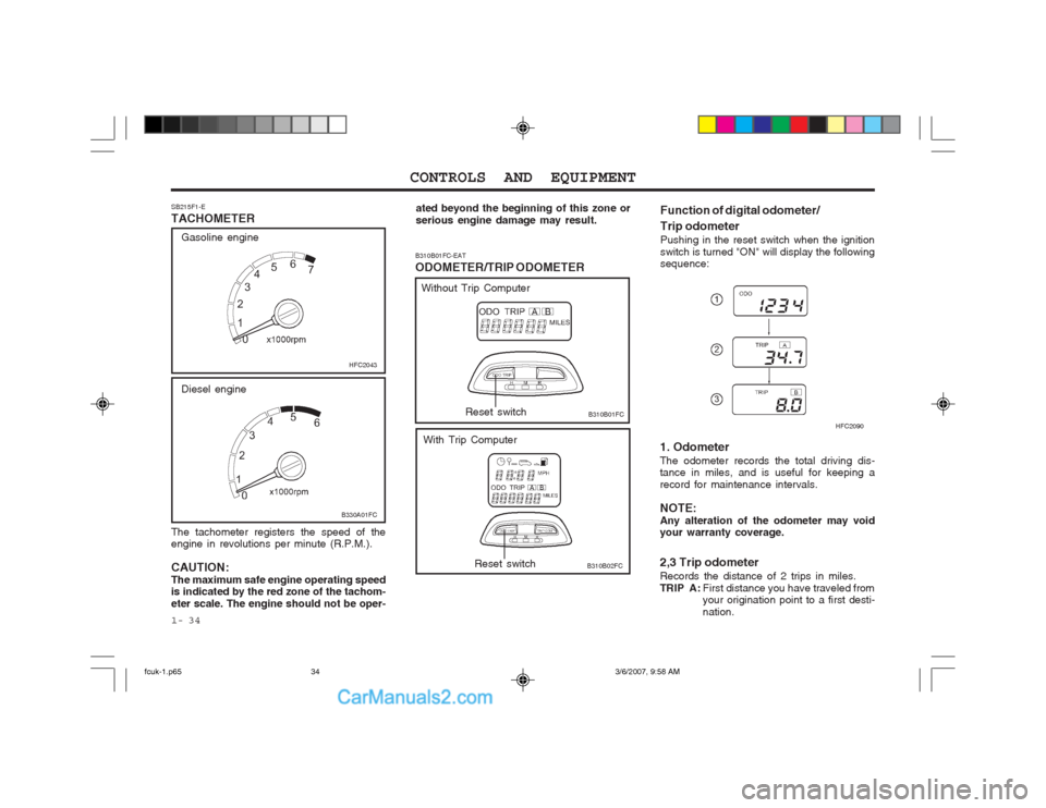
The tachometer registers the speed of the engine in revolutions per minute (R.P.M.). CAUTION: The maximum safe engine operating speed is indicated by the red zone of the tachom- eter scale. The engine should not be oper-
SB215F1-E TACHOMETER
HFC2043
B330A01FC
Diesel engine
Gasoline engine
ated beyond the beginning of this zone or serious engine damage may result.
B310B01FC-EAT ODOMETER/TRIP ODOMETER
B310B01FC Function of digital odometer/ Trip odometer
Pushing in the reset switch when the ignition switch is turned "ON" will display the following sequence:Reset switch
B310B02FCReset switch
Without Trip Computer
With Trip Computer 1. Odometer The odometer records the total driving dis- tance in miles, and is useful for keeping a record for maintenance intervals. NOTE: Any alteration of the odometer may void your warranty coverage. 2,3 Trip odometer Records the distance of 2 trips in miles.
TRIP A :First distance you have traveled from your origination point to a first desti- nation. HFC2090
fcuk-1.p65
3/6/2007, 9:58 AM
34
Page 217 of 317
1- 35
CONTROLS AND EQUIPMENT
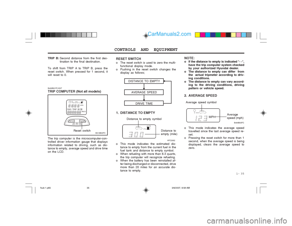
The trip computer is the microcomputer-con- trolled driver information gauge that displays information related to driving, such as dis- tance to empty, average speed and drive time on the LCD.
B310B02FC
B400B01FC-EAT TRIP COMPUTER (Not all models)Reset switch
1. DISTANCE TO EMPTYDISTANCE TO EMPTY
AVERAGE SPEED
DRIVE TIME
Distance to empty symbol
Distance to empty (mile)
o This mode indicates the estimated dis- tance to empty from the current fuel in the fuel tank and distance to empty symbol.
o When refueling with more than 6.3 quarts, the trip computer will recognize refueling.
o When the battery has been reinstalled af-
ter being discharged or disconnected, drivemore than 20 miles for an accurate dis- tance to empty. NOTE:
o If the distance to empty is indicated "- -",
have the trip computer system checked by your authorized Hyundai dealer.
o The distance to empty can differ from the actual tripmeter according to driv- ing conditions.
o The distance to empty can vary accord- ing to the driving conditions, drivingpattern or vehicle speed.
2. AVERAGE SPEED
o This mode indicates the average speed travelled since the last average speed re- set.
o Pressing the reset switch for more than 1
second, when the average speed is being displayed, clears the average speed to zero.
Average speed symbol
Average speed (mph)
HFC2052 B400B02FC
TRIP B :
Second distance from the first des-tination to the final destination.
To shift from TRIP A to TRIP B, press thereset switch. When pressed for 1 second, it will reset to 0.
RESET SWITCH
o The reset switch is used to zero the multi- functional display mode.
o Pushing in the reset switch changes the display as follows;
fcuk-1.p65 3/6/2007, 9:58 AM
35
Page 261 of 317
IN CASE OF EMERGENCY
3-2
CAUTION: Personal injury and damage to the vehicle may occur if jump starting is not per- formed correctly. If any doubt exists as to how this operation should be performed, seek assistance from qualified personnel. WARNING: Motor vehicle batteries contain sulphuric acid and emit hydrogen gas. Protective clothing should be worn and care exer- cised to prevent the acid from coming into contact with skin or clothing and the ve- hicle. Naked lights should not be permitted in the vicinity of the battery. Care should be exercised to prevent sparks occurring during connection. If acid accidentally comes into contact with skin or eyes, the affected area should immediately be flushed CAUTION: If the jump cable is incorrectly installed,
damage to the vehicle electrical system may occur, in particular the electronic components such as the Fuel Injection system computer and the Automatic
Transaxle computer. The battery must never be disconnected whilst the engine is running. SD040A2-E IF THE ENGINE OVERHEATS
If the temperature gauge indicates overheat- ing:
1. Pull off the road and stop as soon as it is safe to do so.
2. Place the gear selector lever in "P" (auto- matic), or neutral (manual transaxle) and set the parking brake. If the air condition- ing is on, turn it off.
3. If coolant is running out under the car or
steam is coming out from under the bonnet stop the engine. Do not open the bonnet until the coolant has stopped running or the steaming has stopped. If there is no visible loss of coolant and no steam, leave the engine running and check to be sure the engine cooling fan is operating.If the fan is not running, turn the engine off.
4. Check to see if the water pump drive belt is missing. If it is not missing, check to seethat it is tight. If the drive belt seems to be
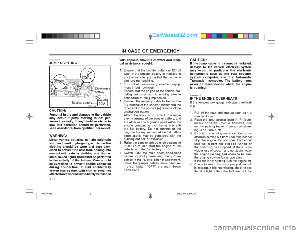
SD030A2-E JUMP STARTING
with copious amounts of water and medi- cal assistance sought.
1. Ensure that the booster battery is 12 volt
type. If the booster battery is installed in another vehicle, ensure that the two vehi- cles are not touching.
2. Turn off all unnecessary electrical equip- ment in both vehicles.
3. Ensure that the engine of the vehicle pro- viding the jump start is running prior to connection of the jump cables.
4. Connect the red jump cable to the positive (+) terminal of the booster battery and theother end to the positive (+) terminal of the discharged battery.
5. Attach the black jump cable to the nega- tive (-) terminal of the booster battery, andthe other end to a ground point within the engine compartment of the vehicle with the flat battery. Do not connect to the negative battery terminal of the flat battery since sparks may be generated with the subsequent risk of explosion.
6. Raise the booster vehicle engine speed to 2,000 r.p.m. and start the engine of thevehicle with the flat battery.
7. Switch "ON" the main beam headlamps before carefully removing the jumper cables in the reverse order of attachment. Once the jumper cables have been re- moved, switch "OFF" the main beam headlamps.
HFC4002
Booster battery Discharged battery
fcuk-3.p65
3/6/2007, 9:59 AM
2