fuel filter Hyundai Matrix 2006 User Guide
[x] Cancel search | Manufacturer: HYUNDAI, Model Year: 2006, Model line: Matrix, Model: Hyundai Matrix 2006Pages: 490, PDF Size: 11.58 MB
Page 210 of 490
6 DO-IT-YOURSELF MAINTENANCE
4
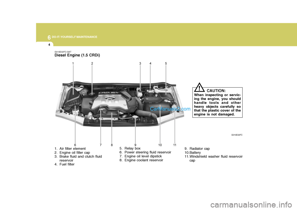
1. Air filter element
2. Engine oil filler cap
3. Brake fluid and clutch fluidreservoir
4. Fuel filter 5. Relay box
6. Power steering fluid reservoir
7. Engine oil level dipstick
8. Engine coolant reservoir
9. Radiator cap
10.Battery
11.Windshield washer fluid reservoir
cap G010E02FC
G010E02FC-GAT
Diesel Engine (1.5 CRDi)
CAUTION:
When inspecting or servic-
ing the engine, you shouldhandle tools and otherheavy objects carefully so that the plastic cover of the engine is not damaged.
!
Page 239 of 490
6
DO-IT-YOURSELF MAINTENANCE
33
G240A01A-AAT
POWER STEERING HOSES
It is suggested that you check the power steering hose connections for fluid leakage at regular intervals. The power steering hoses should be re-placed if there is severe surface crack- ing, scuffing or worn spots. Deteriora- tion of the hose could cause prema-ture failure.
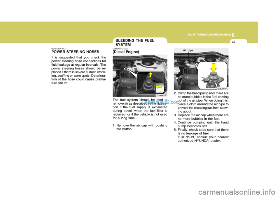
2. Pump the hand pump until there are no more bubbles in the fuel coming out of the air pipe. When doing this, place a cloth around the air pipe to prevent the escaping fuel from spew-ing about.
3. Replace the air cap when there are no more bubbles in the fuel.
4. Continue pumping until the hand pump becomes stiff.
5. Finally, check to be sure that there
is no leakage of fuel. If in doubt, consult your nearest authorized HYUNDAI dealer. G350B01FC
Air pipe
The fuel system should be bled to
remove air as described in the illustra- tion if the fuel supply is exhausted during travel, when the fuel filter is replaced, or if the vehicle is not usedfor a long time.
1. Remove the air cap with pushing the button.
G350A01FC
BLEEDING THE FUEL SYSTEM
G350B01FC-GAT
(Diesel Engine)
Page 240 of 490

6 DO-IT-YOURSELF MAINTENANCE
34
G300A02FC
If the fuel filter warning light illumi- nates during driving, it indicates thatwater has accumulated in the fuel filter. If this occurs, remove the water as described.1. Loosen the drain plug at the bottom of the fuel filter.
2. Tighten the drain plug when water no longer comes out.
3. Check to be sure that the warning lamp illuminates when the ignition key is turned to "ON", and that it goes off when the engine is started. If in doubt, consult your nearest authorized HYUNDAI dealer.
NOTE: It is recommended that water ac-
cumulated in the fuel filter should be removed by an authorized Hyundai dealer. G300B02FC
!WARNING:
o Do not smoke or have any other open flame near the vehicle while bleeding the fuel system.
o Be sure to carefully wipe away
any water drained out in thismanner, because the fuel mixed in the water might be ignited and result in a fire.
REMOVAL OF WATER FROM THE FUEL FILTER
G300A01B-GAT
(Diesel Engine)
Page 250 of 490
7EMISSION CONTROL SYSTEMS
2EMISSION CONTROL SYSTEMS
H010A01A-GAT
(If Installed)
Your Hyundai is equipped with an
emission control system to meet all requirements of the Emission prohibi- tion rules of your province.
There are three emission control sys-
tems which are as follows.
(1) Crankcase emission control sys- tem
(2) Evaporative emission control sys- tem
(3) Exhaust emission control system
In order to assure the proper function
of the emission control systems, it is recommended that you have your carinspected and maintained by an au- thorized Hyundai dealer in accordance with the maintenance schedule in thismanual. H010B01A-AAT
1. Crankcase Emission Control
System
The positive crankcase ventilation
system is employed to prevent airpollution caused by blow-by gasesbeing emitted from the crankcase. This system supplies fresh filtered air to the crankcase through the air in-take hose. Inside the crankcase, the fresh air mixes with blow-by gases, then passes through the PCV valveinto the induction system.
H010C01E-GAT
2. Evaporative Emission Control
System
The Evaporative Emission Control
System is designed to prevent fuel vapors from escaping into the atmo- sphere. Canister
While the engine is inoperative, fuel
vapors generated inside the fuel tank are absorbed and stored in the canis- ter. When the engine is running, thefuel vapors absorbed in the canister are drawn into the induction system through the purge control solenoidvalve. Purge Control Solenoid Valve (PCSV)
The purge control solenoid valve is
controlled by the Engine Control Mod- ule (ECM); when the engine coolant temperature is low during idling, the PCSV closes so that evaporated fuelis not taken into the engine. After the engine warms-up during ordinary driv- ing, the PCSV opens so as to intro-duce evaporated fuel to the engine.
H010D01A-AAT
3. Exhaust Emission Control
System
The Exhaust Emission Control Sys-
tem is a highly effective system which controls exhaust emissions while maintaining good vehicle performance.
Page 265 of 490

10INDEX
2
A Accessory Tray ......................................................... 1-72
Air Bag ...................................................................... 1-37
Air Cleaner Filter ........................................................ 6-17
Air Conditioning
Care ........................................................................ 6-26
Operation ................................................................ 6-26
Switch ..................................................................... 1-89
Air Conditioner Filter .................................................. 1-99
Antenna ................................................................... 1-133
Ashtray ...................................................................... 1-66
Audio System .......................................................... 1-102
Auto Fuel Cut Switch ................................................ 1-82
BBattery .............................................................. 2-21, 6-32
Bleeding The Fuel System ........................................ 6-35
Brake Anti-lock system ..................................................... 2-13
Brake traction control system ................................ 2-14
Checking the brakes ............................................... 6-23
Fluid ........................................................................ 6-24
Pedal clearance ...................................................... 6-29
Pedal free play ....................................................... 6-29
Practices ................................................................ 2-17
Brake Pad Wear Warning Sound ............................... 1-53
Brake Traction Control System ................................. 2-14
Breaking-In your new Hyundai ..................................... 1-3
Bulbs W attage ........................................................... 6-40C
Care of Cassette Tapes ..........................................
1-132
Care of Disc ............................................................ 1-131
Cargo Area Cover ...................................................... 1-81
Cassette Tape Player Operation (H220, H280) ................ .
.................................................................. 1-108, 1-122
Catalytic Converter ...................................................... 7-3
CD Auto changer ....................................................... 1-79
CD Auto Changer (H260, H280) ....................1-116, 1-127
Child-Protector Rear Door Lock ................................... 1-9
Child Restraint System ................................... 1-28 ~ 1-34
Cigarette Lighter ........................................................ 1-65
Clutch
Checking fluid ........................................................ 6-25
Pedal free play ...................................................... 6-28
Combination Light Headlight flasher ..................................................... 1-60
Headlight swi tch ..................................................... 1-59
High-beam switch ................................................... 1-60
Lane change si gnal ................................................. 1-59
Turn signal operation .............................................. 1-59
Compact Disc Player Operation (H260, H280) ................ .
.................................................................. 1-113, 1-124
Cooling Fans ............................................................. 6-34
Corrosion Protection
Cleaning the interior .................................................. 4-5
Protecting your Hyundai from corrosion ................... 4-2
Washing and waxing ................................................. 4-4
Page 280 of 490
YOUR VEHICLE AT A GLANCE
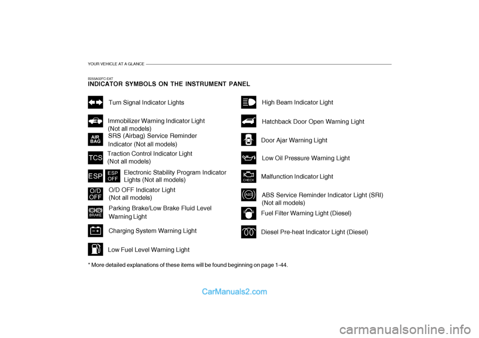
B255A02FC-EAT INDICATOR SYMBOLS ON THE INSTRUMENT PANEL * More detailed explanations of these items will be found beginning on page 1-44.
SRS (Airbag) Service Reminder
Indicator (Not all models)Turn Signal Indicator Lights
Malfunction Indicator Light
Traction Control Indicator Light (Not all models)
O/D OFF Indicator Light (Not all models)
Parking Brake/Low Brake Fluid Level Warning Light
Charging System Warning LightFuel Filter Warning Light (Diesel) Diesel Pre-heat Indicator Light (Diesel)
Immobilizer Warning Indicator Light (Not all models)
ABS Service Reminder Indicator Light (SRI) (Not all models) High Beam Indicator Light Low Oil Pressure Warning Light
Hatchback Door Open Warning Light
Door Ajar Warning Light
Low Fuel Level Warning Light
Electronic Stability Program Indicator Lights (Not all models)
Page 323 of 490

1
CONTROLS AND EQUIPMENT
43
1. Temperature Gauge
2. Tachometer
3. Speedometer
4. Digital Clock
5. Odometer/Trip Odometer/Trip Computer (Not all models)
6. Fuel Gauge
7. Fuel Filter Warning Light
8. Turn Signal Indicator Light
9. Immobiliser Warning Indicator Light
10. SRS (Airbag) Warning Light
11. Diesel Pre-heat Indicator Light
12. Electronic Stability Program (ESP) Indicator Light (Not all models)/Traction Control Indicator Light (Not all models) 13. Parking Brake/Low Brake Fluid Level Warning Light
14. Charging System Warning Light
15. Low Fuel Warning Light
16. High Beam Indicator Light
17. Tail Gate Open Warning Light
18. Door Ajar Warning Light
19. Oil Pressure Warning Light
20. Malfunction Indicator Light (MIL)
21. ABS Warning Light (Not all models)
Page 328 of 490

1CONTROLS AND EQUIPMENT
48
B270B02O-EAT PARKING START WARNING SOUND (Not all models) If the vehicle is driven at 6mph(10km/h) for more than 2~3 seconds, the warning chime will sound continuously when theparking brake engaged.
B900A01A-EAT ACOUSTIC WARNING SOUND (Not all models) The acoustic warning chime sounds when the tail lights are on and the door in driver side is open. This prevents thebattery from discharging when the car is left with the tail lights on. The chime sounds until the tail lights are turned off.
B260S01B-GAT
Diesel Pre-heat Indicator Light(Diesel Engine)
The indicator light illuminates amber when the ignition switch is placed at the "ON" position. The engine can be startedafter the pre-heat indicator light goes off. The illuminating time varies with the water temperature, air temperature andbattery condition. NOTE: If the engine were not started 10 seconds after the preheating is com- pleted, turn the ignition key oncemore to the "LOCK" position, and then to the "ON" position, in order to preheat again.
B265A01FC-GAT Fuel Filter Warning Light (Diesel Engine)
This light illuminates when the engine has started and goes off after a fewseconds. If it lights up whilst the engine is running, it indicates that water has accumulated inside the fuel filter. If thishappens, remove the water from the fuel filter. (Refer to "6-32 page")
Page 422 of 490
5
VEHICLE MAINTENANCE REQUIREMENTS
3
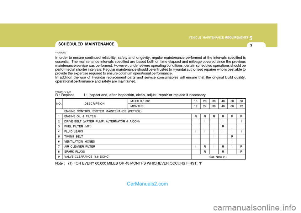
NO.
1 2 3 4 5 6 7 8 9 DESCRIPTION
ENGINE CONTROL SYSTEM MAINTENANCE (PETROL)ENGINE OIL & FILTER DRIVE BELT (WATER PUMP, ALTERNATOR & A/CON) FUEL FILTER (MFI) FLUID LEAKS TIMING BELT VENTILATION HOSES AIR CLEANER FILTER SPARK PLUGS VALVE CLEARANCE (1.8 DOHC)
YF010A2-E In order to ensure continued reliability, safety and longevity, regular maintenance performed at the intervals specified is essential. The maintenance intervals specified are based both on time elapsed and mileage covered since the previous maintenance service was performed. However, under severe operating conditions, certain scheduled operations should be
performed at shorter intervals. Regular maintenance should be entrusted to Hyundai authorised repairer who is best able to provide the expertise required to ensure optimum operational performance. In addition the use of Hyundai replacement parts and service consumables will ensure that the original build quality, operational performance and safety are maintained. F030B01FC-EAT R : Replace I : Inspect and, after inspection, clean, adjust, repair or replace if necessary60 72
R I I
R R
50 60
R
I
R II
4048
R I
R I
R R
30 36
R
II I
20 24
R I I
R R
10 12
R
I I
MILES X 1,000 MONTHS
See Note (1)
Note : (1) FOR EVERY 60,000 MILES OR 48 MONTHS WHICHEVER OCCURS FIRST: "I" SCHEDULED MAINTENANCE
Page 423 of 490
5VEHICLE MAINTENANCE REQUIREMENTS
4
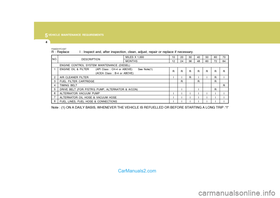
NO.1 2 345678 ENGINE CONTROL SYSTEM MAINTENANCE (DIESEL)
ENGINE OIL & FILTER (API Class : CH-4 or ABOVE) See Note(1)
(ACEA Class : B-4 or ABOVE)
AIR CLEANER FILTER FUEL FILTER CARTRIDGE TIMING BELTDRIVE BELT (FOR P/STR'G PUMP, ALTERNATOR & A/CON)ALTERNATOR VACUUM PUMPALTERNATOR OIL HOSE & VACUUM HOSE FUEL LINES, FUEL HOSE & CONNECTIONS
F030D01FC-EAT
R : Replace I : Inspect and, after inspection, clean, adjust, repair or replace if necessary.
70 84
R I
R II I
60 72
R R R R I I I
50 60
R I I I I
40 48
R I
R
III I
30 36
R R
I I I
20 24
R I
R
III I
10 12
R I I I I
MILES X 1,000 MONTHSDESCRIPTION
Note : (1) ON A DAILY BASIS, WHENEVER THE VEHICLE IS REFUELLED OR BEFORE STARTING A LONG TRIP :"I"