instrument cluster Hyundai Matrix 2007 Owner's Manual
[x] Cancel search | Manufacturer: HYUNDAI, Model Year: 2007, Model line: Matrix, Model: Hyundai Matrix 2007Pages: 490, PDF Size: 12.81 MB
Page 9 of 490
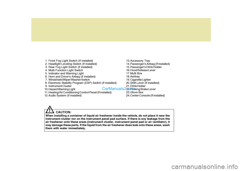
1. Front Fog Light Switch (If installed)
2. Headlight Leveling Switch (If installed)
3. Rear Fog Light Switch (If installed)
4. Multi-Function Light Switch
5. Indicator and Warning Light
6. Horn and Driver's Airbag (If installed)
7. Windshield Wiper/Washer Switch 8. Electronic Stability Program (ESP) Switch (If installed)
9. Instrument Cluster
10. Hazard Warning Light
11. Heating/Air Conditioning Control Panel (If installed)
12. Audio System (If installed)CAUTION:
When installing a container of liquid air freshener inside the vehicle, do not place it near the instrument cluster nor on the instrument panel pad surface. If there is any leakage from the air freshener onto these areas (instrument cluster, instrument panel pad or air ventilator), it may damage these parts. If the liquid from the air freshener does leak onto these areas, washthem with water immediately.
! 13. Accessory Tray
14. Passenger's Airbag (If installed)
15. Passenger's Drink Holder
16. Hood Release Lever
17. Multi Box
18. Ashtray
19. Cigarette Lighter
20. Shift Lever (If installed)
21. Drink Holder
22. Parking Brake Lever
23. Glove Box
24. Center Console (If installed)
Page 11 of 490
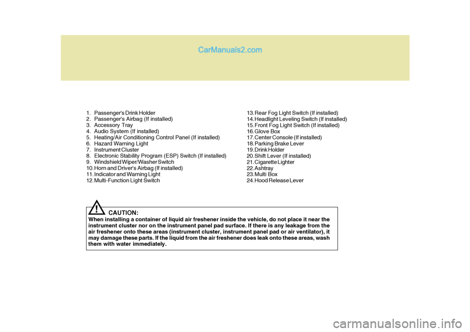
1. Passenger's Drink Holder
2. Passenger's Airbag (If installed)
3. Accessory Tray
4. Audio System (If installed)
5. Heating/Air Conditioning Control Panel (If installed)
6. Hazard Warning Light
7. Instrument Cluster
8. Electronic Stability Program (ESP) Switch (If installed)
9. Windshield Wiper/Washer Switch
10. Horn and Driver's Airbag (If installed)
11. Indicator and Warning Light
12. Multi-Function Light SwitchCAUTION:
When installing a container of liquid air freshener inside the vehicle, do not place it near the instrument cluster nor on the instrument panel pad surface. If there is any leakage from the air freshener onto these areas (instrument cluster, instrument panel pad or air ventilator), itmay damage these parts. If the liquid from the air freshener does leak onto these areas, wash them with water immediately.
! 13. Rear Fog Light Switch (If installed)
14. Headlight Leveling Switch (If installed)
15. Front Fog Light Switch (If installed)
16. Glove Box
17. Center Console (If installed)
18. Parking Brake Lever
19. Drink Holder
20. Shift Lever (If installed)
21. Cigarette Lighter
22. Ashtray
23. Multi Box
24. Hood Release Lever
Page 13 of 490
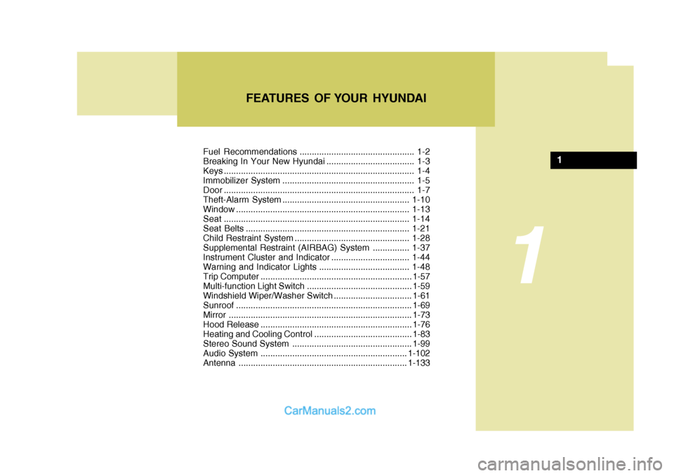
Fuel Recommendations ............................................... 1-2
Breaking In Your New Hyundai .................................... 1-3
Keys .............................................................................. 1-4
Immobilizer System ...................................................... 1-5
Door .............................................................................. 1-7
Theft-Alarm System ....................................................1-10
Window ....................................................................... 1-13
Seat ............................................................................ 1-14
Seat Belts ................................................................... 1-21
Child Restraint System............................................... 1-28
Supplemental Restraint (AIRBAG) System ............... 1-37
Instrument Cluster and Indicator ................................ 1-44
Warning and Indicator Lights ..................................... 1-48
Trip Computer .............................................................. 1-57
Multi-function Light Switch ........................................... 1-59
Windshield Wiper/Washer Switch ................................1-61
Sunroof ........................................................................ 1-69
Mirror ........................................................................... 1-73
Hood R elease .............................................................. 1-76
Heating and Cooling Control .......... ..............................1-83
Stereo Sound System ................................................. 1-99
Audio System ............................................................ 1-102
Antenna ..................................................................... 1-133
FEATURES OF YOUR HYUNDAI
1
1
Page 52 of 490
1FEATURES OF YOUR HYUNDAI
40
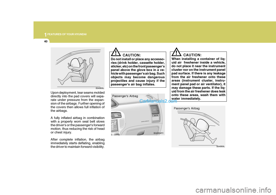
CAUTION:
When installing a container of liq- uid air freshener inside a vehicle,do not place it near the instrument cluster nor on the instrument panel pad surface. If there is any leakagefrom the air freshener onto these areas (instrument cluster, instru- ment panel pad or air ventilator), itmay damage these parts. If the liq- uid from the air freshener does leak onto these areas, wash them withwater immediately.!
CAUTION:
Do not install or place any accesso- ries (drink holder, cassette holder,sticker, etc) on the front passenger's panel above the glove box in a ve- hicle with passenger's air bag. Suchobjects may become dangerous projectiles and cause injury if the passenger's air bag inflates.!
Passenger's AirbagB240B05L
B240B03L
Upon deployment, tear seams molded directly into the pad covers will sepa-rate under pressure from the expan- sion of the airbags. Further opening of the covers then allows full inflation ofthe airbags. A fully inflated airbag in combination with a properly worn seat belt slows the driver's or the passenger's forward motion, thus reducing the risk of heador chest injury. After complete inflation, the airbag immediately starts deflating, enabling the driver to maintain forward visibility. Passenger's Airbag
B240B04FC
Page 56 of 490

1FEATURES OF YOUR HYUNDAI
44INSTRUMENT CLUSTER AND INDICATOR
B260A02FC-GAT GASOLINE ENGINE
B260A02FC
Page 66 of 490
1FEATURES OF YOUR HYUNDAI
54
!
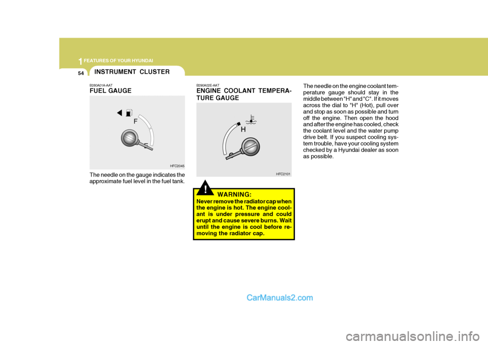
B280A01A-AAT FUEL GAUGE The needle on the gauge indicates the approximate fuel level in the fuel tank. B290A02E-AAT ENGINE COOLANT TEMPERA- TURE GAUGE
HFC2045 HFC2101
WARNING:
Never remove the radiator cap when the engine is hot. The engine cool- ant is under pressure and coulderupt and cause severe burns. Wait until the engine is cool before re- moving the radiator cap. The needle on the engine coolant tem-perature gauge should stay in themiddle between "H" and "C". If it moves across the dial to "H" (Hot), pull over and stop as soon as possible and turnoff the engine. Then open the hood and after the engine has cooled, check the coolant level and the water pumpdrive belt. If you suspect cooling sys- tem trouble, have your cooling system checked by a Hyundai dealer as soonas possible.
INSTRUMENT CLUSTER
Page 161 of 490

2
DRIVING YOUR HYUNDAI
15
!
CAUTION:
When the TCS indicator blinks, SLIP control has been activated. It also means that the road is slippery or your car is accelerating excessively.In this situation, gently release foot pressure from the accelerator pedal and maintain moderate speed.
WARNING:
Traction control is only a driving aid; all normal precautions for driv- ing in inclement weather and onslippery driving surfaces should be observed.! C300D02O-GAT Indicator and Warning The TCS indicator should illuminate when the ignition key is turned to "ON"or "START", but should go out after three seconds. If the indicator does not illuminate,have it checked by an authorized Hyundai dealer. Should there be any unusual condi- tions in the device, TCS illuminates as a warning.If TCS illuminates, pull your car to a safe place and stop the engine. Then, start the engine again to checkif the TCS indicator goes out. If the indicator remains lit even after the engine has been started, haveyour car checked by an authorized Hyundai dealer. NOTE: When the TCS indicator illuminates, traction control is automatically de- activated for safety.
C300B01O-GAT TCS ON Mode In the TCS ON mode, the indicator in the instrument cluster will not be illumi-nated. NOTE:
1) Turn off the engine. Then restart
the engine, and the TCS mode will automatically turn "ON".
2) When the traction control is op-
erating properly, you can feel aslight pulsation in the vehicle. This is only the effect of brakecontrol and indicates nothing unusual.
3) When the engine starts, a click is heard from the engine compart-ment; however, this is only the sound of traction control beingchecked.
4) When moving out of the mud or
fresh snow, pressing the accel-erator pedal may not cause the engine speed to increase.
Page 162 of 490

2 DRIVING YOUR HYUNDAI
16
!
input can all affect whether ESP will be effective in preventing a loss of con-trol. It is still your responsibility to drive and corner at reasonable speeds and to leave a sufficient margin of safety.
CAUTION:
Driving with varying tire or wheelsize may cause the ESP system to malfunction. When replacing tires, make sure they are the same size asyour original tires.
WARNING:
Electronic stability program is onlya driving aid; all normal precau-tions for driving in inclement weather and on slippery road sur- faces should be observed.
!
ELECTRONIC STABILITY PROGRAM (ESP)
C310A01JM-AAT (If installed) The Electronic Stability Program (ESP) system is designed to stabilize thevehicle during cornering manuevers. ESP checks where you are steering and where the vehicle is actually go-ing. ESP applies the brakes at indi- vidual wheels and intervenes in the engine management system to stabi-lize the vehicle. The Electronic Stability Program (ESP) system is an electronic system de- signed to help the driver maintain ve- hicle control under adverse conditions.It is not a substitute for safe driving practices. Factors including speed, road conditions and driver steering C310A01FC
C310B01JM-AAT ESP ON/OFF Mode When the ESP is operating, the ESP indicator in the instrument cluster willblink. If you turn the system off by pressing the ESP switch, the ESP-OFF indica-tor will come on and stay on. In the ESP-OFF mode, the stability control will be deactivated. Adjust your drivingaccordingly. To turn the system back on, press the switch again. The ESP- OFF indicator should go off. NOTE: The ESP mode will automatically be turned ON after the engine isturned off and restarted.
Page 246 of 490
6 DO-IT-YOURSELF MAINTENANCE
42
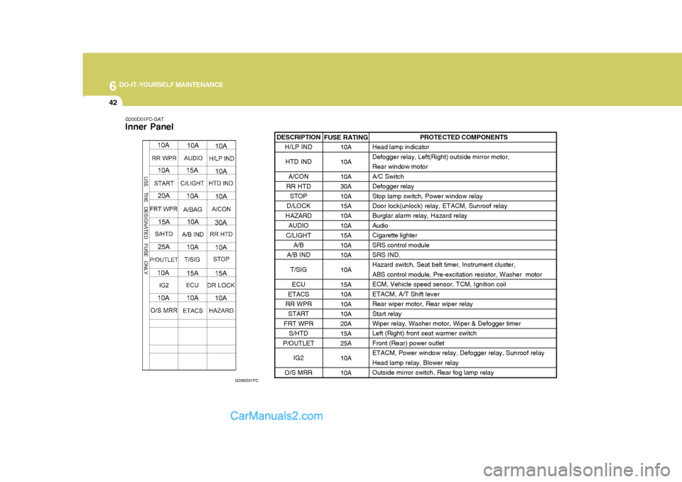
G200D01FC-GAT Inner Panel
G200D01FC
DESCRIPTIONH/LP IND
HTD IND
A/CON
RR HTD STOP
D/LOCK
HAZARD AUDIO
C/LIGHT A/B
A/B IND
T/SIG
ECU
ETACS
RR WPR
START
FRT WPR S/HTD
P/OUTLET
IG2
O/S MRRPROTECTED COMPONENTS
Head lamp indicator Defogger relay, Left(Right) outside mirror motor,Rear window motorA/C SwitchDefogger relayStop lamp switch, Power window relay Door lock(unlock) relay, ETACM, Sunroof relay Burglar alarm relay, Hazard relayAudioCigarette lighterSRS control moduleSRS IND. Hazard switch, Seat belt timer, Instrument cluster, ABS control module, Pre-excitation resistor, Washer motorECM, Vehicle speed sensor, TCM, Ignition coilETACM, A/T Shift leverRear wiper motor, Rear wiper relayStart relay Wiper relay, Washer motor, Wiper & Defogger timer Left (Right) front seat warmer switchFront (Rear) power outletETACM, Power window relay, Defogger relay, Sunroof relayHead lamp relay, Blower relayOutside mirror switch, Rear fog lamp relay
FUSE RATING
10A 10A 10A 30A10A15A 10A 10A15A10A10A 10A 15A 10A10A 10A 20A15A25A 10A 10A
Page 265 of 490

10INDEX
4
Heating and VentilationAir flow control ........................................................ 1-85
Air intake control .................................................... 1-87
Bi-level heating ....................................................... 1-88
Fan speed control ................................................... 1-84
Heating controls ...................................................... 1-87
Temperature control ................................................ 1-84
High-mounted Rear Stoplight .....................................1-76
Hood Release ............................................................ 1-76
Horn ........................................................................... 1-82
I Ignition Sw itch ............................................................. 2-3
Immobilizer S ystem ..................................................... 1-5
Instrument Cluster and Indicator .................. 1-44 ~ 1-47
Interior Light Interior light ............................................................. 1-71
Map light ................................................................. 1-71
Intermittent Wiper ...................................................... 1-62
J Jump Starting .............................................................. 3-3
K
Keys ............................................................................ 1-4 If you lose your keys ............................................. 3-15
Positions ................................................................... 2-4 L Lubrication Chart
.......................................................... 9-4
Luggage Net .............................................................. 1-80
MMaintenance Intervals Explanation of scheduled maintenance items .......... 5-8Maintenance under severe usage conditions ............ 5-7
Scheduled maintenance .................................. 5-4 ~ 5-6
Service requirements ................................................ 5-2
Mirror
Day-night inside rearview ....... .................................1-75
Outside rearvi ew ..................................................... 1-73
Multi Box ................................................................... 1-72
O
Odometer ................................................................... 1-56
Outside Rearview Mirror Heater................................. 1-74
PParking Brake ............................................................ 1-68
Power Outlet .............................................................. 1-66
Power Steering Fluid Level ....................................... 6-32
Pre-tensioner Seat Belt ............................................. 1-35