tank Hyundai Nexo 2019 Owner's Manual
[x] Cancel search | Manufacturer: HYUNDAI, Model Year: 2019, Model line: Nexo, Model: Hyundai Nexo 2019Pages: 560, PDF Size: 24.2 MB
Page 148 of 560
3-61
Convenient features of your vehicle
3
- Fuel Cell StackOverheats
If the gauge pointer moves
beyond the normal range area
toward the "H" position, it indi-
cates overheating that may dam-
age the fuel cell stack.Hydrogen fuel gauge
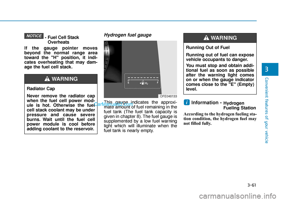
This gauge indicates the approxi-
mate amount of fuel remaining in the
fuel tank (The fuel tank capacity is
given in chapter 8). The fuel gauge is
supplemented by a low fuel warning
light which will illuminate when the
fuel tank is nearly empty.Information -Hydrogen
Fueling Station
According to the hydrogen fueling sta-
tion condition, the hydrogen fuel may
not filled fully.i
NOTICE
Running Out of Fuel
Running out of fuel can expose
vehicle occupants to danger.
You must stop and obtain addi-
tional fuel as soon as possible
after the warning light comes
on or when the gauge indicator
comes close to the ''E'' (Empty)
level.
WARNING
Radiator Cap
Never remove the radiator cap
when the fuel cell power mod-
ule is hot. Otherwise the fuel
cell stack coolant may be under
pressure and cause severe
burns. Wait until the fuel cell
power module is cool before
adding coolant to the reservoir.
WARNING
OFE048133
Page 150 of 560
3-63
Convenient features of your vehicle
3
Range
The range is the estimated dis-tance the vehicle can be driven
with the remaining fuel.
If the estimated distance is below 1 mi. (1 km), the trip computer will
display "---" as range.
If the hydrogen supply line is empty, the gauge may indicate that the
hydrogen is not in the hydrogen
tank.
Information
• If the vehicle is not on level groundor the battery power has been inter-
rupted, the range function may not
operate correctly.
• The range may differ from the actu- al driving distance as it is only an
estimate of the available driving
range for the vehicle and driving
conditions.
• The range may vary significantly based on driving conditions, driving
habits, and condition of the vehicle.
Gear shift indicator
This indicator displays which gear is
selected.
i
OFE048108NOFE048105
Page 153 of 560
3-66
Icy Road Warning Light(if equipped)
This warning light is to warn the driver
the road may be icy.
When the temperature on the out-
side temperature gauge is approxi-
mately below 40°F (4°C), the Icy
Road Warning Light and Outside
Temperature Gauge blinks and then
illuminates. Also, the warning chime
sounds 1 time.
The Icy Road Warning function can
be activated or deactivated from the
Vehicle Settings mode in the AVN
screen.
Information
If the icy road warning light appears
while driving, you should drive more
attentively and safely, refraining from
over-speeding, rapid acceleration, sud-
den braking or sharp turning, etc.
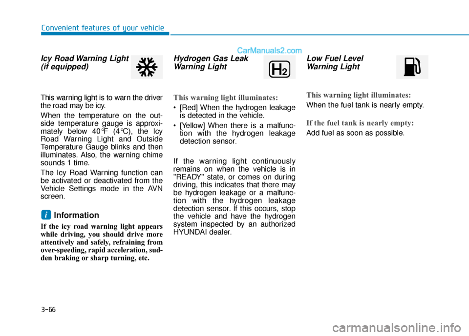
Hydrogen Gas LeakWarning Light
This warning light illuminates:
[Red] When the hydrogen leakage
is detected in the vehicle.
[Yellow] When there is a malfunc- tion with the hydrogen leakage
detection sensor.
If the warning light continuously
remains on when the vehicle is in
"READY" state, or comes on during
driving, this indicates that there may
be hydrogen leakage or a malfunc-
tion with the hydrogen leakage
detection sensor. If this occurs, stop
the vehicle and have the hydrogen
system inspected by an authorized
HYUNDAI dealer.
Low Fuel Level Warning Light
This warning light illuminates:
When the fuel tank is nearly empty.
If the fuel tank is nearly empty:
Add fuel as soon as possible.
i
Convenient features of your vehicle
Page 392 of 560
5-126
Driving your vehicle
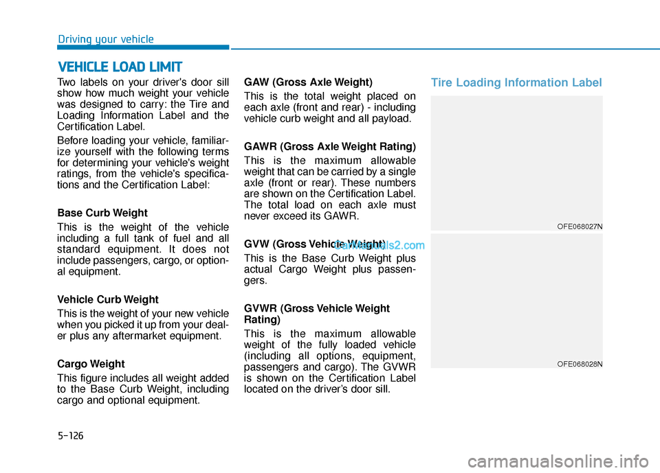
Two labels on your driver's door sill
show how much weight your vehicle
was designed to carry: the Tire and
Loading Information Label and the
Certification Label.
Before loading your vehicle, familiar-
ize yourself with the following terms
for determining your vehicle's weight
ratings, from the vehicle's specifica-
tions and the Certification Label:
Base Curb Weight
This is the weight of the vehicle
including a full tank of fuel and all
standard equipment. It does not
include passengers, cargo, or option-
al equipment.
Vehicle Curb Weight
This is the weight of your new vehicle
when you picked it up from your deal-
er plus any aftermarket equipment.
Cargo Weight
This figure includes all weight added
to the Base Curb Weight, including
cargo and optional equipment. GAW (Gross Axle Weight)
This is the total weight placed on
each axle (front and rear) - including
vehicle curb weight and all payload.
GAWR (Gross Axle Weight Rating)
This is the maximum allowable
weight that can be carried by a single
axle (front or rear). These numbers
are shown on the Certification Label.
The total load on each axle must
never exceed its GAWR.
GVW (Gross Vehicle Weight)
This is the Base Curb Weight plus
actual Cargo Weight plus passen-
gers.
GVWR (Gross Vehicle Weight
Rating)
This is the maximum allowable
weight of the fully loaded vehicle
(including all options, equipment,
passengers and cargo). The GVWR
is shown on the Certification Label
located on the driver’s door sill.
Tire Loading Information Label
V V
E
EH
H I
IC
C L
LE
E
L
L O
O A
AD
D
L
L I
IM
M I
IT
T
OFE068027N
OFE068028N
Page 406 of 560
6-9
What to do in an emergency
1. Pull off the road and stop as soonas it is safe to do so.
2. Shift to P (Park) and set the park- ing brake. If the air conditioning is
on, turn it off.
3. If coolant is running out under the vehicle or steam is coming out
from the hood, stop the vehicle.
Do not open the hood until the
coolant has stopped running or
the steaming has stopped. If there
is no visible loss of coolant and no
steam, leave the vehicle running
and check to be sure the vehicle
cooling fan is operating. If the fan
is not running, turn the vehicle off. 4. Check for coolant leaking from the
radiator, hoses or under the vehi-
cle. (If the air conditioning had
been in use, it is normal for cold
water to be draining from it when
you stop.)
5. If coolant is leaking out, stop the vehicle immediately and call the
nearest authorized HYUNDAI
dealer for assistance.
I IF
F
T
T H
H E
E
V
V E
EH
H I
IC
C L
LE
E
O
O V
VE
ER
R H
H E
EA
A T
TS
S
6
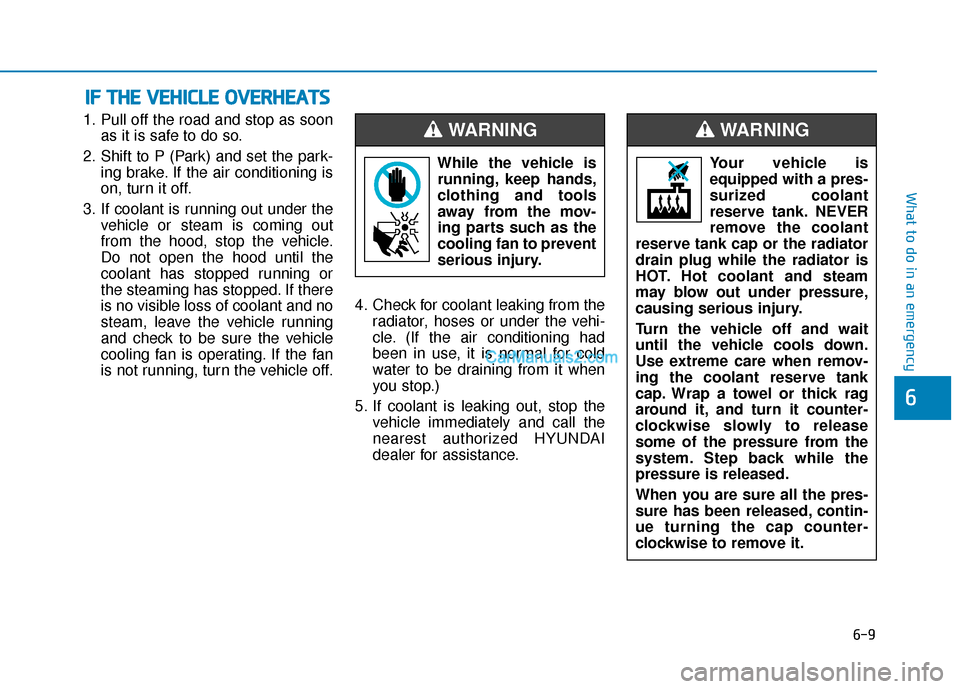
While the vehicle is
running, keep hands,
clothing and tools
away from the mov-
ing parts such as the
cooling fan to prevent
serious injury.
WARNING
Your vehicle is
equipped with a pres-
surized coolant
reserve tank. NEVER
remove the coolant
reserve tank cap or the radiator
drain plug while the radiator is
HOT. Hot coolant and steam
may blow out under pressure,
causing serious injury.
Turn the vehicle off and wait
until the vehicle cools down.
Use extreme care when remov-
ing the coolant reserve tank
cap. Wrap a towel or thick rag
around it, and turn it counter-
clockwise slowly to release
some of the pressure from the
system. Step back while the
pressure is released.
When you are sure all the pres-
sure has been released, contin-
ue turning the cap counter-
clockwise to remove it.
WARNING
Page 505 of 560
Introduction of FCEV .........................................................H2
The components of FCEV..................................................H3
Fuel cell stack ........................................................................\
...........H4
FCEV system module .......................................................................H\
4
High pressure hydrogen storage tanks ......................................H5
Battery system........................................................................\
..........H5
Features of FCEV .............................................................H10
How to Start the Vehicle ..............................................................H10
How to Stop the Vehicle ..............................................................H11
Virtual Engine Sound System......................................................H11
Fuel filler door ........................................................................\
........H12
Warning and indicator lights .......................................................H15
LCD Display Messages ..................................................................H16
FCEV mode........................................................................\
...............H21
When the high voltage battery is weak ...................................H25
If the 12 volt battery is discharged...........................................H25
Emergency while driving ..............................................................H26
Customer Q&A Guide .......................................................H30
F FC
C E
E V
V
V
V e
eh
h i
ic
c l
le
e
S
S y
ys
st
te
e m
m
O
O v
ve
e r
rv
v i
ie
e w
w
FCEV : Fuel Cell Electric Vehicle
Page 506 of 560
H2
An FCEV is an electric vehicle which is driven using the electricity generated from the fuel cell.
The power system of the FCEV is composed of the following:
- The fuel cell stack which generates the electricity
- The device which controls the heat generated after supplying the hydrogen and air for chemical reaction of the stack
- The inverter which converts the DC created from the stack to AC
- The traction motor which generates propelling power using the supplied AC
- Air processing system
- Fuel processing system
The hydrogen tanks that stores the hydrogen supplied to the fuel cell can be fueled at 70 MPa.
❈FCEV is Fuel Cell Electric Vehicle
I IN
N T
TR
R O
O D
DU
U C
CT
T I
IO
O N
N
O
O F
F
F
F C
C E
E V
V
Page 507 of 560
H3
T
TH
H E
E
C
C O
O M
M P
PO
O N
NE
EN
N T
TS
S
O
O F
F
F
F C
C E
E V
V
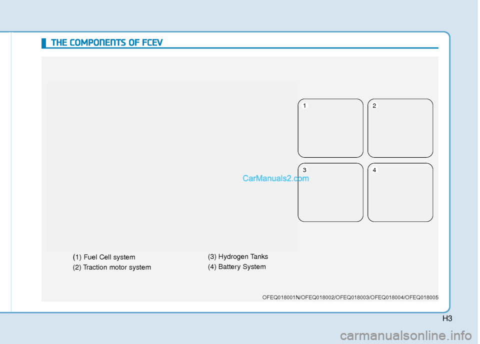
OFEQ018001N/OFEQ018002/OFEQ018003/OFEQ018004/OFEQ018005
(1) Fuel Cell system
(2) Traction motor system (3) Hydrogen Tanks
(4) Battery System
12
34
Page 508 of 560
H4
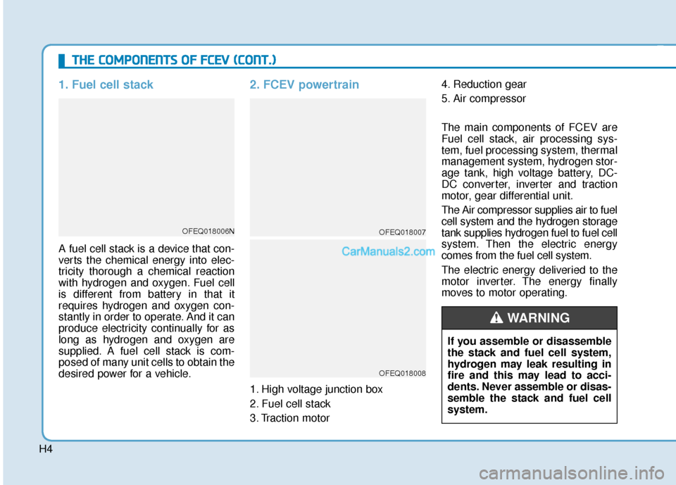
1. Fuel cell stack
A fuel cell stack is a device that con-
verts the chemical energy into elec-
tricity thorough a chemical reaction
with hydrogen and oxygen. Fuel cell
is different from battery in that it
requires hydrogen and oxygen con-
stantly in order to operate. And it can
produce electricity continually for as
long as hydrogen and oxygen are
supplied. A fuel cell stack is com-
posed of many unit cells to obtain the
desired power for a vehicle.
2. FCEV powertrain
1. High voltage junction box
2. Fuel cell stack
3. Traction motor4. Reduction gear
5. Air compressor
The main components of FCEV are
Fuel cell stack, air processing sys-
tem, fuel processing system, thermal
management system, hydrogen stor-
age tank, high voltage battery, DC-
DC converter, inverter and traction
motor, gear differential unit.
The Air compressor supplies air to fuel
cell system and the hydrogen storage
tank supplies hydrogen fuel to fuel cell
system. Then the electric energy
comes from the fuel cell system.
The electric energy deliveried to the
motor inverter. The energy finally
moves to motor operating.
T T
H
H E
E
C
C O
O M
M P
PO
O N
NE
EN
N T
TS
S
O
O F
F
F
F C
C E
E V
V
(
( C
C O
O N
NT
T.
.)
)
OFEQ018006NOFEQ018007
OFEQ018008
If you assemble or disassemble
the stack and fuel cell system,
hydrogen may leak resulting in
fire and this may lead to acci-
dents. Never assemble or disas-
semble the stack and fuel cell
system.
WARNING
Page 509 of 560
H5
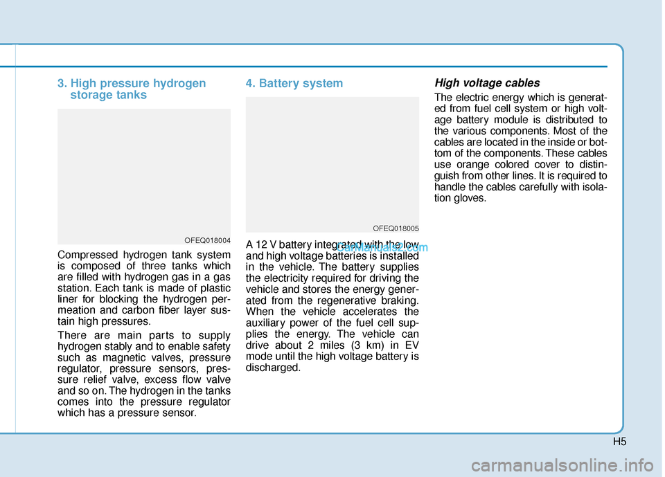
3. High pressure hydrogenstorage tanks
Compressed hydrogen tank system
is composed of three tanks which
are filled with hydrogen gas in a gas
station. Each tank is made of plastic
liner for blocking the hydrogen per-
meation and carbon fiber layer sus-
tain high pressures.
There are main parts to supply
hydrogen stably and to enable safety
such as magnetic valves, pressure
regulator, pressure sensors, pres-
sure relief valve, excess flow valve
and so on. The hydrogen in the tanks
comes into the pressure regulator
which has a pressure sensor.
4. Battery system
A 12 V battery integrated with the low
and high voltage batteries is installed
in the vehicle. The battery supplies
the electricity required for driving the
vehicle and stores the energy gener-
ated from the regenerative braking.
When the vehicle accelerates the
auxiliary power of the fuel cell sup-
plies the energy. The vehicle can
drive about 2 miles (3 km) in EV
mode until the high voltage battery is
discharged.
High voltage cables
The electric energy which is generat-
ed from fuel cell system or high volt-
age battery module is distributed to
the various components. Most of the
cables are located in the inside or bot-
tom of the components. These cables
use orange colored cover to distin-
guish from other lines. It is required to
handle the cables carefully with isola-
tion gloves.
OFEQ018004
OFEQ018005