instrument cluster Hyundai Santa Fe 2007 User Guide
[x] Cancel search | Manufacturer: HYUNDAI, Model Year: 2007, Model line: Santa Fe, Model: Hyundai Santa Fe 2007Pages: 355, PDF Size: 13.03 MB
Page 134 of 355
1FEATURES OF YOUR HYUNDAI
122
!
WARNING:
o Keep the cruise control ON/OFF switch
off when not using the cruise control
to avoid inadvertently setting a speed.
o Use the cruise control system only
when traveling on open highways in
good weather.
o Do not use the cruise control when it
may not be safe to keep the car at a
constant speed, for instance, driving
in heavy or varying traffic, or on slip-
pery (rainy, icy or snow-covered) or
winding roads or over 6% up-hill or
down-hill roads.
o Pay particular attention to the driving
conditions whenever using the cruise
control system.
o During cruise-speed driving of a
manual transaxle vehicle, do not shift
into neutral without depressing the
clutch pedal, since the engine will be
overrevved. If this happens, depress
the clutch pedal or release the cruise
control ON/OFF switch.
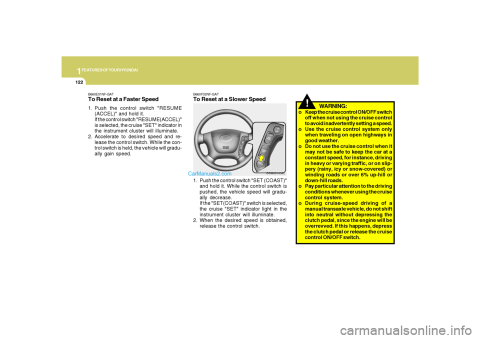
B660F02NF-GATTo Reset at a Slower Speed1. Push the control switch "SET (COAST)"
and hold it. While the control switch is
pushed, the vehicle speed will gradu-
ally decrease.
If the "SET(COAST)" switch is selected,
the cruise "SET" indicator light in the
instrument cluster will illuminate.
2. When the desired speed is obtained,
release the control switch.
OCM051030L
B660E01NF-GATTo Reset at a Faster Speed1. Push the control switch "RESUME
(ACCEL)" and hold it.
If the control switch "RESUME(ACCEL)"
is selected, the cruise "SET" indicator in
the instrument cluster will illuminate.
2. Accelerate to desired speed and re-
lease the control switch. While the con-
trol switch is held, the vehicle will gradu-
ally gain speed.
Page 227 of 355
2
DRIVING YOUR HYUNDAI
16
!
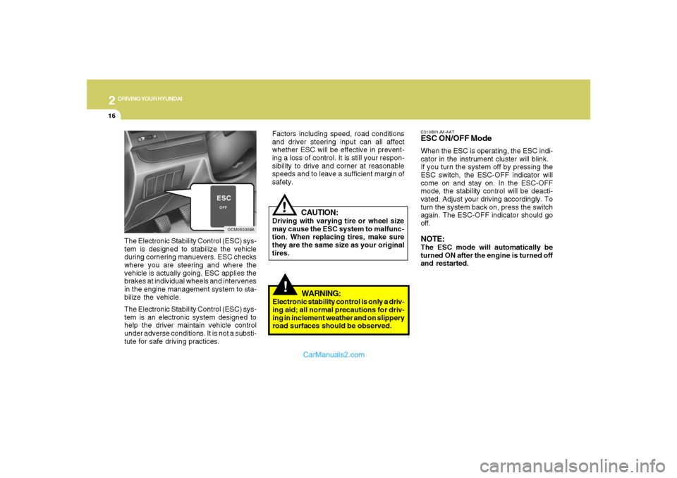
C310B01JM-AATESC ON/OFF ModeWhen the ESC is operating, the ESC indi-
cator in the instrument cluster will blink.
If you turn the system off by pressing the
ESC switch, the ESC-OFF indicator will
come on and stay on. In the ESC-OFF
mode, the stability control will be deacti-
vated. Adjust your driving accordingly. To
turn the system back on, press the switch
again. The ESC-OFF indicator should go
off.NOTE:The ESC mode will automatically be
turned ON after the engine is turned off
and restarted.
OCM053009A
The Electronic Stability Control (ESC) sys-
tem is designed to stabilize the vehicle
during cornering manuevers. ESC checks
where you are steering and where the
vehicle is actually going. ESC applies the
brakes at individual wheels and intervenes
in the engine management system to sta-
bilize the vehicle.
The Electronic Stability Control (ESC) sys-
tem is an electronic system designed to
help the driver maintain vehicle control
under adverse conditions. It is not a substi-
tute for safe driving practices.
CAUTION:
Driving with varying tire or wheel size
may cause the ESC system to malfunc-
tion. When replacing tires, make sure
they are the same size as your original
tires.
!
Factors including speed, road conditions
and driver steering input can all affect
whether ESC will be effective in prevent-
ing a loss of control. It is still your respon-
sibility to drive and corner at reasonable
speeds and to leave a sufficient margin of
safety.
WARNING:
Electronic stability control is only a driv-
ing aid; all normal precautions for driv-
ing in inclement weather and on slippery
road surfaces should be observed.
Page 232 of 355
2
DRIVING YOUR HYUNDAI
21
GOOD BRAKING PRACTICESC130A02A-AAT
WARNING:
o Whenever leaving vehicle or parking,
always set the parking brake as far as
possible and fully engage the vehicle's
transaxle into the park position. Ve-
hicles not fully engaged in park with
the parking brake set are at risk for
moving inadvertently and injuring
yourself or others.
o All vehicles should always have the
parking brake fully engaged when
parking to avoid inadvertent move-
ment of the car which can injure occu-
pants or pedestrians.
o Nothing should be carried on top of
the shelf panel behind the rear seat. If
there were an accident or a sudden
stop, such objects could move for-
ward and cause damage to the ve-
hicle or injure the occupants.
!
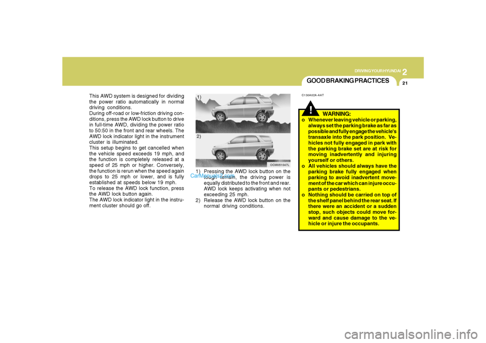
This AWD system is designed for dividing
the power ratio automatically in normal
driving conditions.
During off-road or low-friction driving con-
ditions, press the AWD lock button to drive
in full-time AWD, dividing the power ratio
to 50:50 in the front and rear wheels. The
AWD lock indicator light in the instrument
cluster is illuminated.
This setup begins to get cancelled when
the vehicle speed exceeds 19 mph, and
the function is completely released at a
speed of 25 mph or higher. Conversely,
the function is rerun when the speed again
drops to 25 mph or lower, and is fully
established at speeds below 19 mph.
To release the AWD lock function, press
the AWD lock button again.
The AWD lock indicator light in the instru-
ment cluster should go off.1) Pressing the AWD lock button on the
tough terrain, the driving power is
equally distributed to the front and rear.
AWD lock keeps activating when not
exceeding 25 mph.
2) Release the AWD lock button on the
normal driving conditions.
OCM051047L
1)
2)
Page 319 of 355
6
DO-IT-YOURSELF MAINTENANCE
33
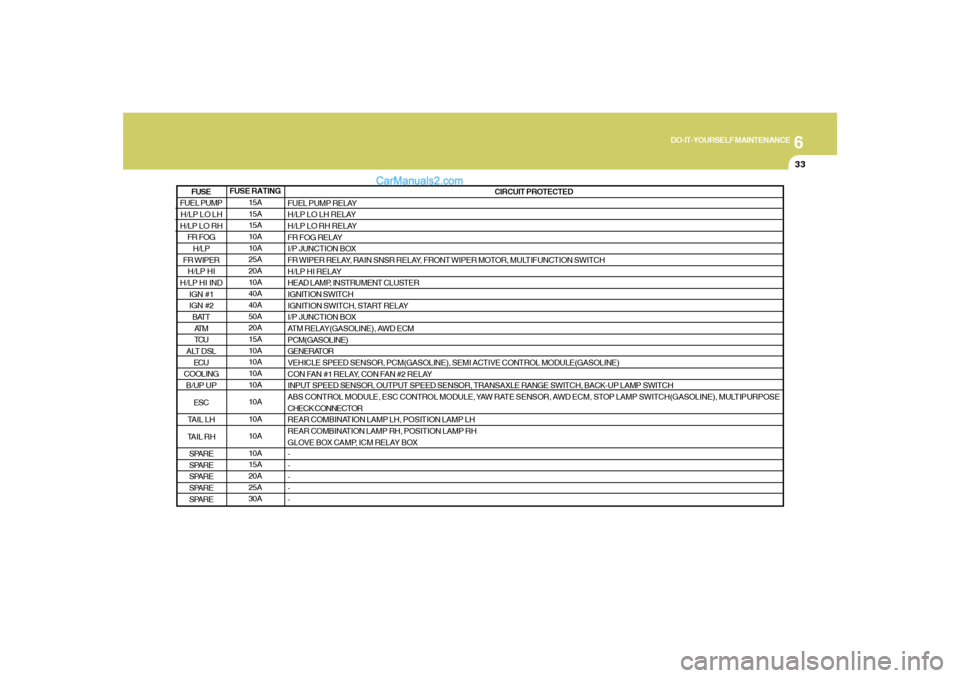
FUSE RATING
15A
15A
15A
10A
10A
25A
20A
10A
40A
40A
50A
20A
15A
10A
10A
10A
10A
10A
10A
10A
10A
15A
20A
25A
30ACIRCUIT PROTECTED
FUEL PUMP RELAY
H/LP LO LH RELAY
H/LP LO RH RELAY
FR FOG RELAY
I/P JUNCTION BOX
FR WIPER RELAY, RAIN SNSR RELAY, FRONT WIPER MOTOR, MULTIFUNCTION SWITCH
H/LP HI RELAY
HEAD LAMP, INSTRUMENT CLUSTER
IGNITION SWITCH
IGNITION SWITCH, START RELAY
I/P JUNCTION BOX
ATM RELAY(GASOLINE), AWD ECM
PCM(GASOLINE)
GENERATOR
VEHICLE SPEED SENSOR, PCM(GASOLINE), SEMI ACTIVE CONTROL MODULE(GASOLINE)
CON FAN #1 RELAY, CON FAN #2 RELAY
INPUT SPEED SENSOR, OUTPUT SPEED SENSOR, TRANSAXLE RANGE SWITCH, BACK-UP LAMP SWITCH
ABS CONTROL MODULE, ESC CONTROL MODULE, YAW RATE SENSOR, AWD ECM, STOP LAMP SWITCH(GASOLINE), MULTIPURPOSE
CHECK CONNECTOR
REAR COMBINATION LAMP LH, POSITION LAMP LH
REAR COMBINATION LAMP RH, POSITION LAMP RH
GLOVE BOX CAMP, ICM RELAY BOX
-
-
-
-
-
FUEL PUMP
H/LP LO LH
H/LP LO RH
FR FOG
H/LP
FR WIPER
H/LP HI
H/LP HI IND
IGN #1
IGN #2
BATT
AT M
TCU
ALT DSL
ECU
COOLING
B/UP UP
ESC
TAIL LH
TAIL RH
SPARE
SPARE
SPARE
SPARE
SPAREFUSE
Page 320 of 355
6
DO-IT-YOURSELF MAINTENANCE
34
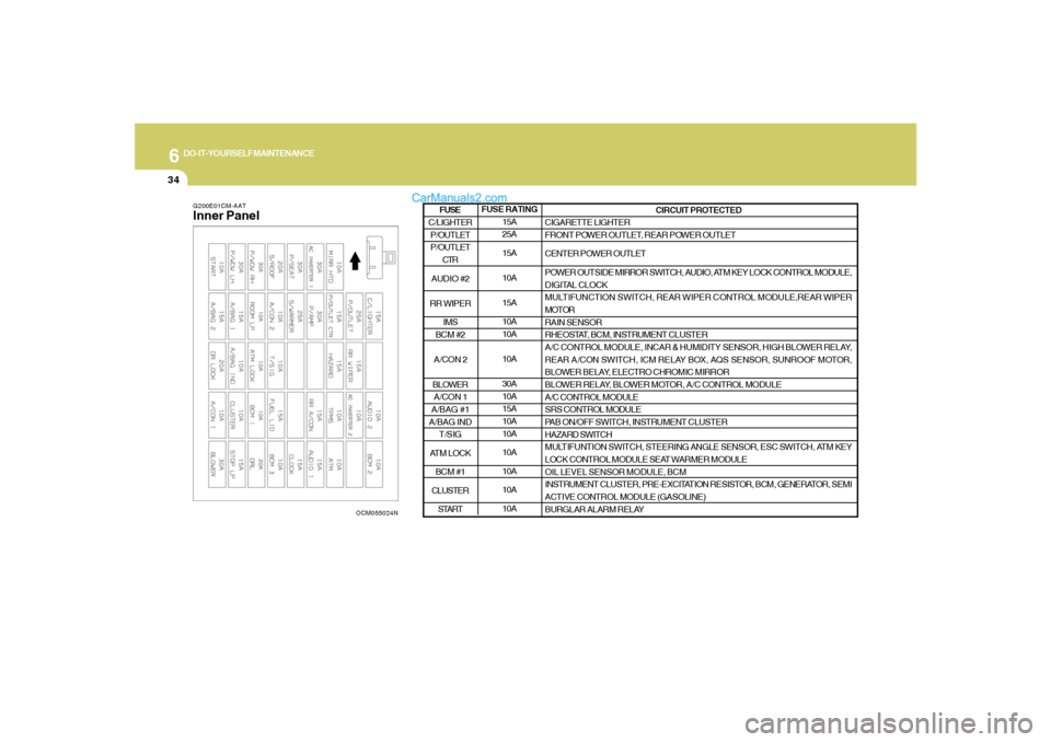
G200E01CM-AATInner Panel
OCM055024N
FUSE RATING
15A
25A
15A
10A
15A
10A
10A
10A
30A
10A
15A
10A
10A
10A
10A
10A
10ACIRCUIT PROTECTED
CIGARETTE LIGHTER
FRONT POWER OUTLET, REAR POWER OUTLET
CENTER POWER OUTLET
POWER OUTSIDE MIRROR SWITCH, AUDIO, ATM KEY LOCK CONTROL MODULE,
DIGITAL CLOCK
MULTIFUNCTION SWITCH, REAR WIPER CONTROL MODULE,REAR WIPER
MOTOR
RAIN SENSOR
RHEOSTAT, BCM, INSTRUMENT CLUSTER
A/C CONTROL MODULE, INCAR & HUMIDITY SENSOR, HIGH BLOWER RELAY,
REAR A/CON SWITCH, ICM RELAY BOX, AQS SENSOR, SUNROOF MOTOR,
BLOWER BELAY, ELECTRO CHROMIC MIRROR
BLOWER RELAY, BLOWER MOTOR, A/C CONTROL MODULE
A/C CONTROL MODULE
SRS CONTROL MODULE
PAB ON/OFF SWITCH, INSTRUMENT CLUSTER
HAZARD SWITCH
MULTIFUNTION SWITCH, STEERING ANGLE SENSOR, ESC SWITCH, ATM KEY
LOCK CONTROL MODULE SEAT WARMER MODULE
OIL LEVEL SENSOR MODULE, BCM
INSTRUMENT CLUSTER, PRE-EXCITATION RESISTOR, BCM, GENERATOR, SEMI
ACTIVE CONTROL MODULE (GASOLINE)
BURGLAR ALARM RELAY
C/LIGHTER
P/OUTLET
P/OUTLET
CTR
AUDIO #2
RR WIPER
IMS
BCM #2
A/CON 2
BLOWER
A/CON 1
A/BAG #1
A/BAG IND
T/SIG
ATM LOCK
BCM #1
CLUSTER
STARTFUSE
Page 321 of 355
6
DO-IT-YOURSELF MAINTENANCE
35
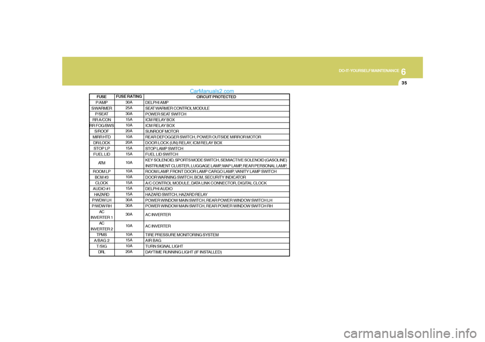
FUSE RATING
30A
25A
30A
15A
10A
20A
10A
20A
15A
15A
10A
10A
10A
15A
15A
15A
30A
30A
30A
10A
10A
15A
10A
20ACIRCUIT PROTECTED
DELPHI AMP
SEAT WARMER CONTROL MODULE
POWER SEAT SWITCH
ICM RELAY BOX
ICM RELAY BOX
SUNROOF MOTOR
REAR DEFOGGER SWITCH, POWER OUTSIDE MIRROR MOTOR
DOOR LOCK (UN) RELAY, ICM RELAY BOX
STOP LAMP SWITCH
FUEL LID SWITCH
KEY SOLENOID, SPORTS MODE SWITCH, SEMIACTIVE SOLENOID (GASOLINE)
INSTRUMENT CLUSTER, LUGGAGE LAMP, MAP LAMP, REAR PERSONAL LAMP,
ROOM LAMP, FRONT DOOR LAMP CARGO LAMP, VANITY LAMP SWITCH
DOOR WARNING SWITCH, BCM, SECURITY INDICATOR
A/C CONTROL MODULE, DATA LINK CONNECTOR, DIGITAL CLOCK
DELPHI AUDIO
HAZARD SWITCH, HAZARD RELAY
POWER WINDOW MAIN SWITCH, REAR POWER WINDOW SWITCH LH
POWER WINDOW MAIN SWITCH, REAR POWER WINDOW SWITCH RH
AC INVERTER
AC INVERTER
TIRE PRESSURE MONITORING SYSTEM
AIR BAG
TURN SIGNAL LIGHT
DAYTIME RUNNING LIGHT (IF INSTALLED)
P/AMP
S/WARMER
P/SEAT
RR A/CON
RR FOG/BWS
S/ROOF
MIRR HTD
DR/LOCK
STOP LP
FUEL LID
AT M
ROOM LP
BCM #3
CLOCK
AUDIO #1
HAZARD
P/WDW LH
P/WDW RH
AC
INVERTER 1
AC
INVERTER 2
TPMS
A/BAG 2
T/SIG
DRLFUSE
Page 351 of 355
10
INDEX
4
Air intake control switch ............................................................1-126
Bi-level heating..........................................................................1-128
Defrosting / Defogging ..............................................................1-133
Fan speed control (Blower control)..........................................1-126
Temperature control.................................................................1-130
High-Mounted Rear Stop Light ......................................................1-112
Hood Release.................................................................................1-115
Horn..............................................................................................1-119
I
Ignition Switch ...................................................................................... 2-5
Instrument Cluster and Indicator Lights...........................................1-62
Instrument Panel Light Control (Rheostat).......................................1-84
Interior Light.......................................................................................1-93
J
Jump Starting...................................................................................... 3-3
K
Keys................................................................................................... 1-3
If you lose your keys ...................................................................3-21
Positions......................................................................................... 2-5
L
Light Bulbs Replacement ..................................................................6-24
Luggage Compartment ..................................................................1-109
Cargo security screen ..............................................................1-109
Luggage Net ..............................................................................1-110
Luggage under tray ...................................................................1-111M
Maintenance Intervals
Explanation of scheduled maintenance items ............................... 5-7
Maintenance under severe usage conditions............................... 5-6
Scheduled maintenance................................................................ 5-4
Service requirements.................................................................... 5-2
Mirrors
Automatic Dimming Rear View Mirror With Compass ................1-99
Day-night inside rearview mirror .................................................1-99
Homelink mirror.........................................................................1-102
Outside rearview mirror ...............................................................1-98
Outside rearview mirror Heater ..................................................1-98
O
Odometer / Trip Odometer ...............................................................1-72
Occupant Classification System ......................................................1-52
P
Parking Brake.................................................................................
1-108
Power Outlet......................................................................................1-86
Power Steering Fluid Level ...............................................................6-23
R
Rear Seat
Adjusting seatback angle .............................................................1-22
Folding rear seatback ..................................................................1-23
Rear Window Defroster Switch ........................................................1-88
Reporting Safety Defects .................................................................8-17
Risk of Rollover................................................................................... 2-3
Roof Rack......................................................................................1-111