fuel cap Hyundai Santa Fe 2009 Owner's Manual - RHD (UK, Australia)
[x] Cancel search | Manufacturer: HYUNDAI, Model Year: 2009, Model line: Santa Fe, Model: Hyundai Santa Fe 2009Pages: 269, PDF Size: 9.78 MB
Page 65 of 269
1FEATURES OF YOUR HYUNDAI
54
!
OCM029011L
INSTRNMENT CLUSTER
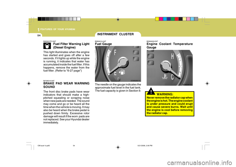
B280A01A-AAT Fuel Gauge The needle on the gauge indicates the approximate fuel level in the fuel tank.The fuel capacity is given in Section 9. B290A02A-DAT Engine Coolant Temperature Gauge
OCM029012L
WARNING:
Never remove the radiator cap when the engine is hot. The engine coolantis under pressure and could erupt and cause severe burns. Wait until the engine is cool before removingthe radiator cap.
B270A01A-AAT BRAKE PAD WEAR WARNING SOUND The front disc brake pads have wear indicators that should make a high-pitched squealing or scraping noise when new pads are needed. The sound may come and go or be heard all thetime when the vehicle is moving. It may also be heard when the brake pedal is pushed down firmly. Excessive rotordamage will result if the worn pads are not replaced. See your Hyundai dealer immediately.
B265A01FC-GAT
Fuel Filter Warning Light (Diesel Engine)
This light illuminates when the engine has started and goes off after a fewseconds. If it lights up while the engine is running, it indicates that water has accumulated inside the fuel filter. If thishappens, remove the water from the fuel filter. (Refer to "6-27 page")
CM-aust-1a.p65 5/21/2008, 2:06 PM
54
Page 99 of 269
1FEATURES OF YOUR HYUNDAI
88
!WARNING:
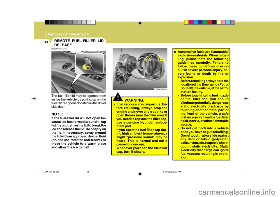
o Fuel vapours are dangerous. Be- fore refuelling, always stop the engine and never allow sparks or open flames near the filler area. Ifyou need to replace the filler cap, use a genuine Hyundai replace- ment part.If you open the fuel filler cap dur- ing high ambient temperatures, a slight "pressure sound" may beheard. This is normal and not a cause for concern. Whenever you open the fuel fillercap, turn it slowly.
REMOTE FUEL-FILLER LID RELEASE
B560A01CM-DAT The fuel-filler lid may be opened from inside the vehicle by pulling up on thefuel-filler lid opener located on the driver side door. NOTE: If the fuel-filler lid will not open be- cause ice has formed around it, tap lightly or push on the lid to break theice and release the lid. Do not pry on the lid. If necessary, spray around the lid with an approved de-icer fluid(do not use radiator anti-freeze) or move the vehicle to a warm place and allow the ice to melt. OCM052014R
OCM052015
o Automotive fuels are flammable/
explosive materials. When refuel- ling, please note the followingguidelines carefully. Failure to follow these guidelines may re- sult in severe personal injury, se-vere burns or death by fire or explosion.
- Before refuelling always note the
location of the Emergency Petrol Shut-Off, if available, at the petrol station facility.
- Before touching the fuel nozzle or fuel filler cap, you shouldeliminate potentially dangerousstatic electricity discharge by touching another metal part of the front of the vehicle, a safedistance away from the fuel filler neck, nozzle, or other flammable source.
- Do not get back into a vehicle once you have begun refuelling.Do not touch, rub or slide againstany item or fabric (polyester, satin, nylon, etc.) capable of pro- ducing static electricity. Staticelectricity discharge can ignite fuel vapours resulting in explo- sion.
CM-aust-1a.p65 5/21/2008, 2:09 PM
88
Page 100 of 269
1
FEATURES OF YOUR HYUNDAI
89
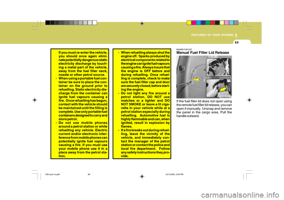
B560B01CM-GAT Manual Fuel Filler Lid Release If the fuel filler lid does not open using the remote fuel filler lid release, you canopen it manually. Unsnap and remove the panel in the cargo area. Pull the handle outward.
OCM052017
If you must re-enter the vehicle, you should once again elimi- nate potentially dangerous staticelectricity discharge by touch- ing a metal part of the vehicle, away from the fuel filler neck,nozzle or other petrol source.
- When using a portable fuel con-
tainer be sure to place the con-tainer on the ground prior to refuelling. Static electricity dis- charge from the container canignite fuel vapours causing a fire. Once refuelling has begun, contact with the vehicle shouldbe maintained until the filling is complete. Use only portable fuel containers designed to carry andstore petrol.
- Do not use mobile phones
around a petrol station or whilerefuelling any vehicle. Electric current and/or electronic inter- ference from mobile phones canpotentially ignite fuel vapours causing a fire. If you must use your mobile phone use it in aplace away from the petrol sta- tion.- When refuelling always shut theengine off. Sparks produced by electrical components related tothe engine can ignite fuel vapours causing a fire. Always insure that the engine is OFF before andduring refuelling. Once refuel- ling is complete, check to make sure the fuel filler cap and doorare securely closed, before start- ing the engine.
- Do not light any fire around a petrol station. DO NOT usematches or a lighter and DO NOT SMOKE or leave a lit ciga-rette in your vehicle while at a petrol station especially during refuelling. Automotive fuel ishighly flammable and can, when ignited, result in explosion by flames.
- If a fire breaks out during refuel- ling, leave the vicinity of thevehicle, and immediately con-tact the manager of the petrol station or contact the police and local fire department. Followany safety instructions they pro- vide.
CM-aust-1a.p65 5/21/2008, 2:09 PM
89
Page 148 of 269
2
DRIVING YOUR HYUNDAI
3
!
BEFORE STARTING THE ENGINE
C020A01CM-DAT Before you start the engine, you should always:
1. Look around the vehicle to be sure
there are no flat tyres, puddles of oil, water or other indications of possible trouble.
2. After entering the car, check to be sure the hand brake is engaged.
3. Check that all windows, and lights are clean.
4. Check that the interior and exterior
mirrors are clean and in position.
5. Check your seat, seatback and head- rest to be sure they are in their properpositions.
6. Lock all the doors.
7. Fasten your seat belt and be sure
that all other occupants have fas- tened theirs.
8. Turn off all lights and accessories
that are not needed.
9. When you turn the ignition switch to "ON", check that all appropriate warn-ing lights are operating and that youhave sufficient fuel.
10. Check the operation of warning lights
and all bulbs when key is in the "ON"position.
C020A01HP-DAT
o In a collision crash, an unbelted
person is significantly more likelyto die than a person wearing aseatbelt.
RISK OF ROLLOVER
WARNING:
o Utility vehicle has a significantly higher collision rate than othertype of vehicles.
o Utility vehicle have higher ground clearance and a narrower trackto make them capable of perform-ing in a wide variety of off-road applications. Specific design characteristics give them a highercentre of gravity than ordinary cars. An advantage of the higher ground clearance is a better viewof the road allowing you to antici- pate problem. They are not de- signed for cornering at the samespeeds as conventional 2-wheel drive vehicles any more than low- slung sports cars are designed toperform satisfactorily under off- road conditions. If at all possible, avoid sharp turns or abrupt ma-neuvers. As with other vehicles of this type, failure to operate this vehicle correctly may result inloss of control or vehicle rollover.
CM-aust-2.p65 5/19/2008, 6:34 PM
3
Page 180 of 269
3
WHAT TO DO IN AN EMERGENCY
5
!
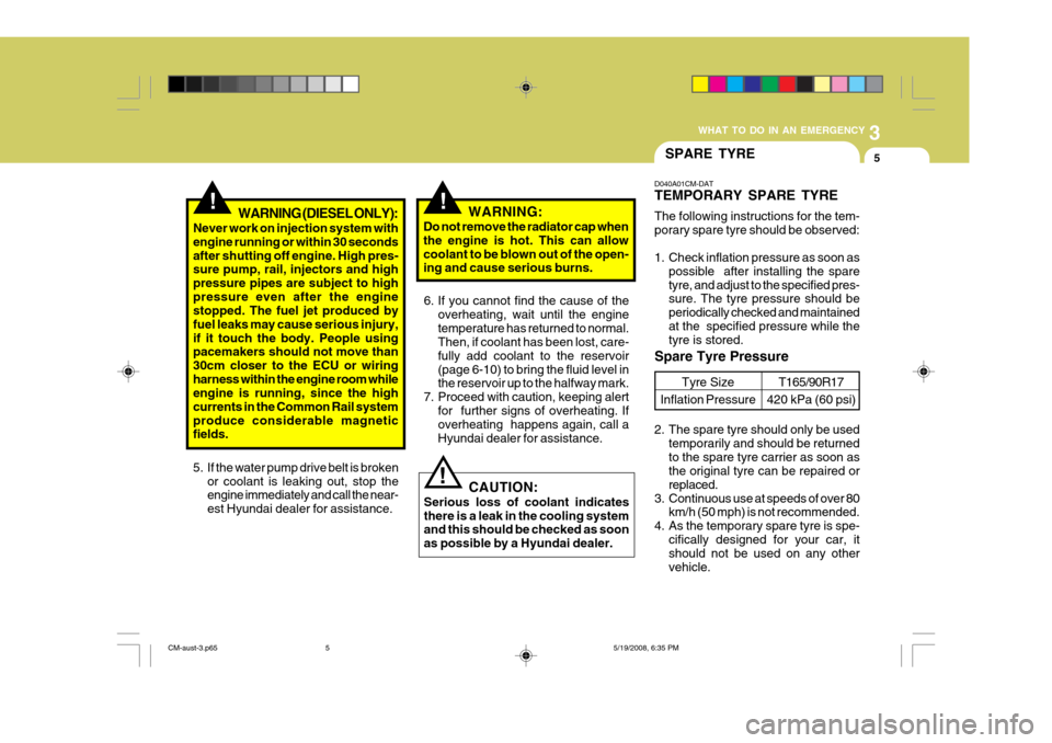
5. If the water pump drive belt is broken
or coolant is leaking out, stop the engine immediately and call the near- est Hyundai dealer for assistance. WARNING:
Do not remove the radiator cap whenthe engine is hot. This can allowcoolant to be blown out of the open- ing and cause serious burns.
!WARNING (DIESEL ONLY):
Never work on injection system with engine running or within 30 secondsafter shutting off engine. High pres- sure pump, rail, injectors and high pressure pipes are subject to highpressure even after the engine stopped. The fuel jet produced by fuel leaks may cause serious injury,if it touch the body. People using pacemakers should not move than 30cm closer to the ECU or wiringharness within the engine room while engine is running, since the high currents in the Common Rail systemproduce considerable magnetic fields. 6. If you cannot find the cause of the
overheating, wait until the engine temperature has returned to normal. Then, if coolant has been lost, care- fully add coolant to the reservoir(page 6-10) to bring the fluid level in the reservoir up to the halfway mark.
7. Proceed with caution, keeping alert for further signs of overheating. Ifoverheating happens again, call a Hyundai dealer for assistance.
CAUTION:
Serious loss of coolant indicatesthere is a leak in the cooling system and this should be checked as soon as possible by a Hyundai dealer.
!
SPARE TYRE
D040A01CM-DAT TEMPORARY SPARE TYRE The following instructions for the tem- porary spare tyre should be observed:
1. Check inflation pressure as soon as possible after installing the spare tyre, and adjust to the specified pres- sure. The tyre pressure should be periodically checked and maintainedat the specified pressure while the tyre is stored.
Spare Tyre Pressure
Tyre Size
Inflation PressureT165/90R17
420 kPa (60 psi)
2. The spare tyre should only be used temporarily and should be returned to the spare tyre carrier as soon as the original tyre can be repaired or replaced.
3. Continuous use at speeds of over 80 km/h (50 mph) is not recommended.
4. As the temporary spare tyre is spe-
cifically designed for your car, it should not be used on any other vehicle.
CM-aust-3.p65 5/19/2008, 6:35 PM
5
Page 200 of 269
5VEHICLE MAINTENANCE REQUIREMENTS
4REGULAR SERVICING
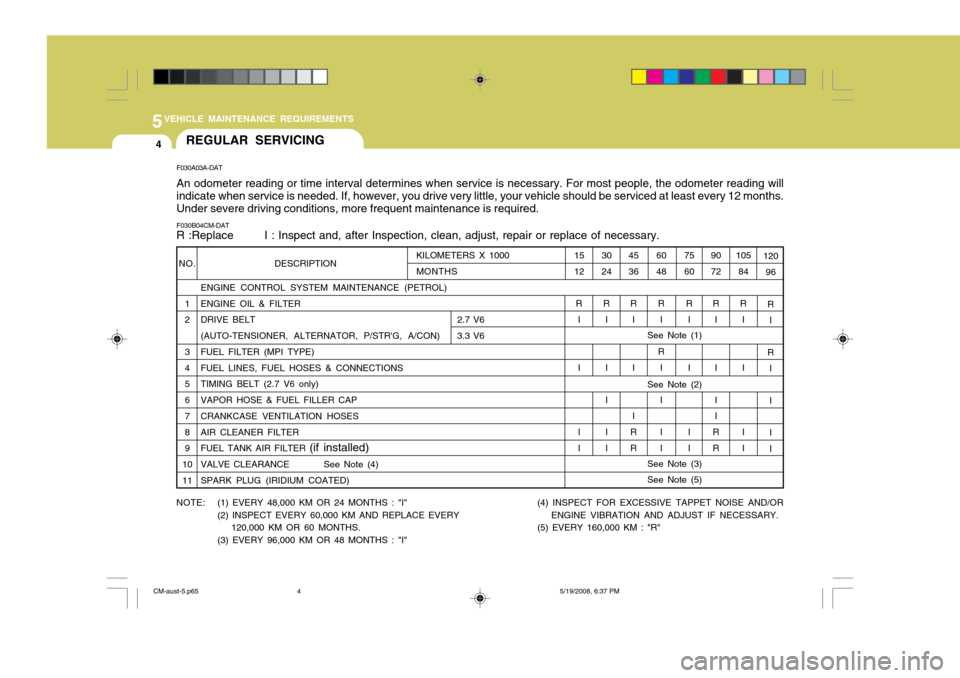
F030A03A-DAT An odometer reading or time interval determines when service is necessary. For most people, the odometer reading will indicate when service is needed. If, however, you drive very little, your vehicle should be serviced at least every 12 months. Under severe driving conditions, more frequent maintenance is required.
See Note (3) See Note (5)
NO.
12 3 4 5 6 7 8 9
1011
F030B04CM-DAT R :Replace I : Inspect and, after Inspection, clean, adjust, repair or replace of necessary.
105
84
R I I I I 120
96
R I
R I II I
9072
R I I I I
RR
75 60
R I I I I
60 48
R I
R I II I
45 36
R I I I
R R
30 24
R I I II I
15 12
R I I I I
KILOMETERS X 1000 MONTHS DESCRIPTION ENGINE CONTROL SYSTEM MAINTENANCE (PETROL) ENGINE OIL & FILTER
DRIVE BELT
2.7 V6
(AUTO-TENSIONER, ALTERNATOR, P/STR'G, A/CON) 3.3 V6FUEL FILTER (MPI TYPE) FUEL LINES, FUEL HOSES & CONNECTIONS TIMING BELT (2.7 V6 only) VAPOR HOSE & FUEL FILLER CAP CRANKCASE VENTILATION HOSES AIR CLEANER FILTER FUEL TANK AIR FILTER (if installed)
VALVE CLEARANCE See Note (4)SPARK PLUG (IRIDIUM COATED)
NOTE: (1) EVERY 48,000 KM OR 24 MONTHS : "I" (2) INSPECT EVERY 60,000 KM AND REPLACE EVERY
120,000 KM OR 60 MONTHS.
(3) EVERY 96,000 KM OR 48 MONTHS : "I"
See Note (2)
See Note (1)
(4) INSPECT FOR EXCESSIVE TAPPET NOISE AND/OR ENGINE VIBRATION AND ADJUST IF NECESSARY.
(5) EVERY 160,000 KM : "R"
CM-aust-5.p65 5/19/2008, 6:37 PM
4
Page 205 of 269
5
VEHICLE MAINTENANCE REQUIREMENTS
9
F060E01A-AAT
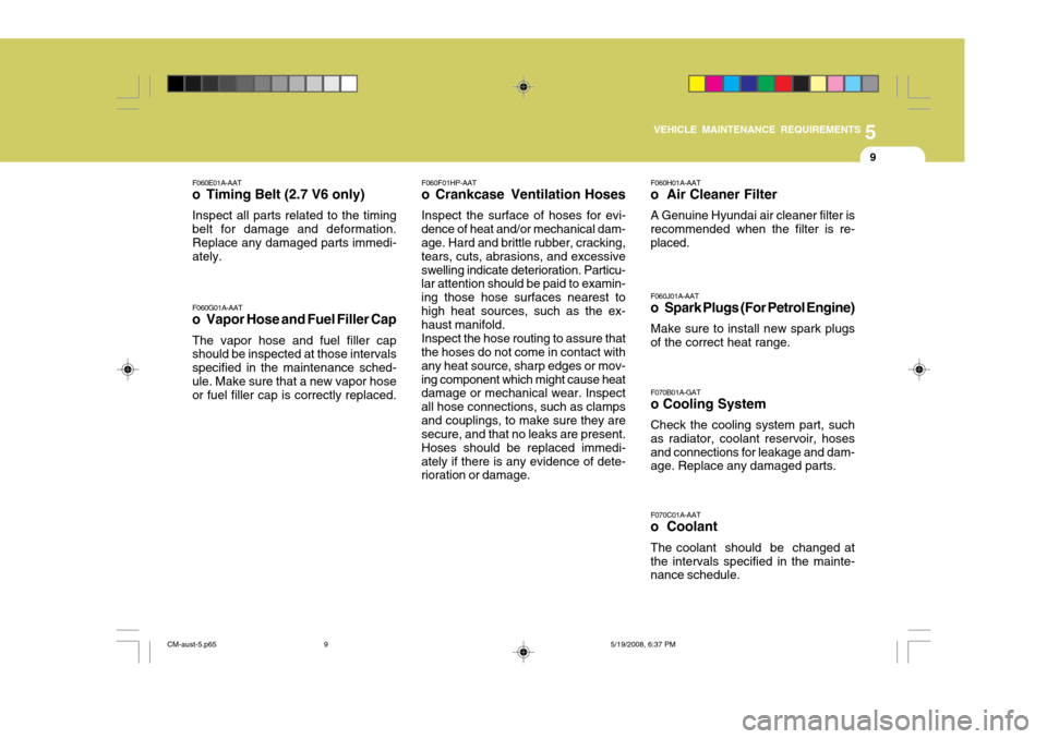
o Timing Belt (2.7 V6 only)
Inspect all parts related to the timing belt for damage and deformation. Replace any damaged parts immedi- ately. F060G01A-AAT
o Vapor Hose and Fuel Filler Cap
The vapor hose and fuel filler cap should be inspected at those intervals specified in the maintenance sched-ule. Make sure that a new vapor hose or fuel filler cap is correctly replaced. F060F01HP-AAT
o Crankcase Ventilation Hoses
Inspect the surface of hoses for evi-
dence of heat and/or mechanical dam-age. Hard and brittle rubber, cracking, tears, cuts, abrasions, and excessiveswelling indicate deterioration. Particu- lar attention should be paid to examin- ing those hose surfaces nearest tohigh heat sources, such as the ex- haust manifold.
Inspect the hose routing to assure that
the hoses do not come in contact with any heat source, sharp edges or mov-ing component which might cause heat damage or mechanical wear. Inspect all hose connections, such as clampsand couplings, to make sure they are secure, and that no leaks are present. Hoses should be replaced immedi-ately if there is any evidence of dete- rioration or damage. F060H01A-AAT
o Air Cleaner Filter
A Genuine Hyundai air cleaner filter is recommended when the filter is re- placed. F060J01A-AAT
o Spark Plugs (For Petrol Engine)
Make sure to install new spark plugs of the correct heat range. F070C01A-AAT
o Coolant
The coolant should be changed at the intervals specified in the mainte- nance schedule.
F070B01A-GAT o Cooling System Check the cooling system part, such as radiator, coolant reservoir, hosesand connections for leakage and dam- age. Replace any damaged parts.
CM-aust-5.p65
5/19/2008, 6:37 PM
9
Page 211 of 269
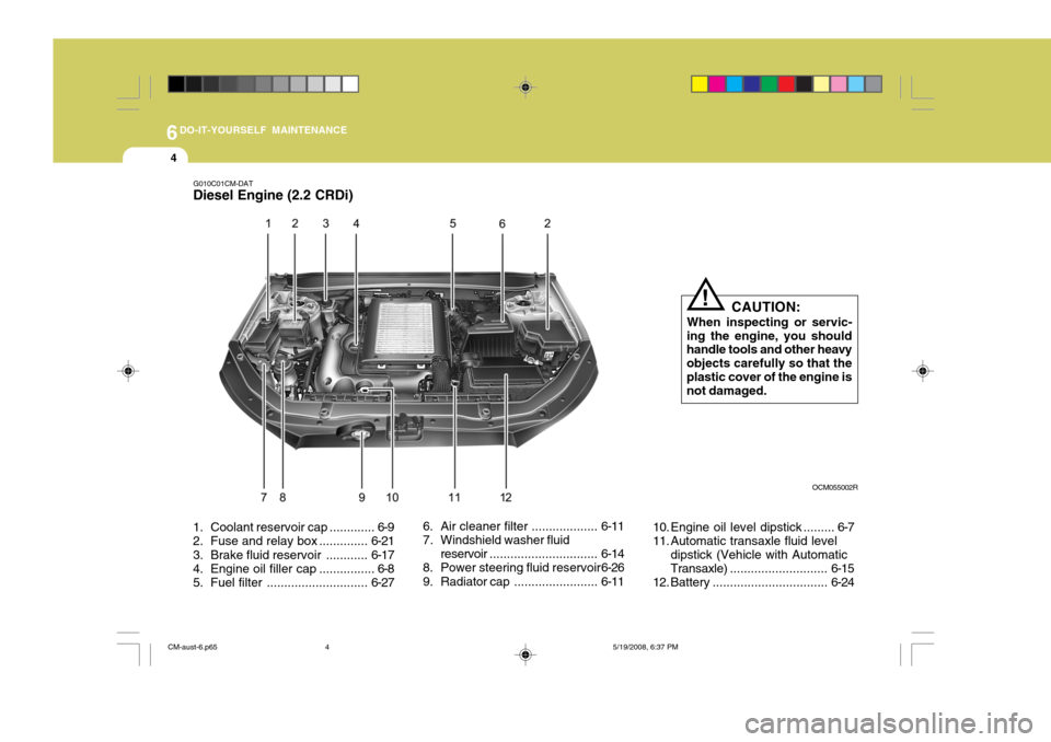
6DO-IT-YOURSELF MAINTENANCE
4
1. Coolant rese rvoir cap ............. 6-9
2. Fuse and relay box .............. 6-21
3. Brake fluid reservoir ............ 6-17
4. Engine oil filler cap ................ 6-8
5. Fuel filter ............................. 6-276. Air cleaner filter ...................
6-11
7. Windshield washer fluid
reservoir ............................... 6-14
8. Power steering fluid reservoir 6-26
9. Radiator cap ........................6-1110. Engine oil level dipstick ......... 6-7
11. Automatic transaxle fluid level
dipstick (Vehicle with AutomaticTransaxle) ............................ 6-15
12. Battery ................................. 6-24
G010C01CM-DAT
Diesel Engine (2.2 CRDi)
CAUTION:
When inspecting or servic-
ing the engine, you should handle tools and other heavy objects carefully so that theplastic cover of the engine is not damaged.
!
OCM055002R
CM-aust-6.p65 5/19/2008, 6:37 PM
4
Page 250 of 269
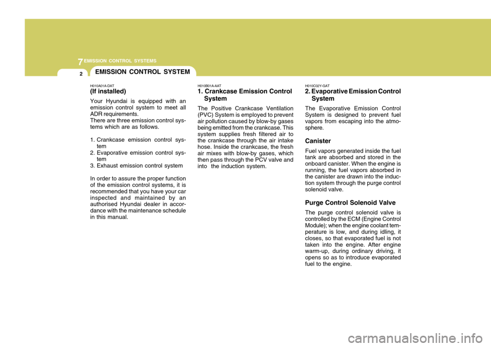
7EMISSION CONTROL SYSTEMS
2EMISSION CONTROL SYSTEM
H010A01A-DAT (If installed) Your Hyundai is equipped with an emission control system to meet all ADR requirements. There are three emission control sys- tems which are as follows.
1. Crankcase emission control sys- tem
2. Evaporative emission control sys- tem
3. Exhaust emission control systemIn order to assure the proper function of the emission control systems, it is recommended that you have your carinspected and maintained by an authorised Hyundai dealer in accor- dance with the maintenance schedulein this manual. H010B01A-AAT
1. Crankcase Emission Control
System
The Positive Crankcase Ventilation
(PVC) System is employed to prevent air pollution caused by blow-by gases being emitted from the crankcase. Thissystem supplies fresh filtered air to the crankcase through the air intake hose. Inside the crankcase, the freshair mixes with blow-by gases, which then pass through the PCV valve and into the induction system. H010C02Y-GAT
2. Evaporative Emission Control
System
The Evaporative Emission Control
System is designed to prevent fuel vapors from escaping into the atmo- sphere. Canister
Fuel vapors generated inside the fuel
tank are absorbed and stored in the onboard canister. When the engine isrunning, the fuel vapors absorbed in the canister are drawn into the induc- tion system through the purge controlsolenoid valve. Purge Control Solenoid Valve
The purge control solenoid valve is
controlled by the ECM (Engine Control Module); when the engine coolant tem- perature is low, and during idling, it closes, so that evaporated fuel is nottaken into the engine. After engine warm-up, during ordinary driving, it opens so as to introduce evaporatedfuel to the engine.
Page 261 of 269
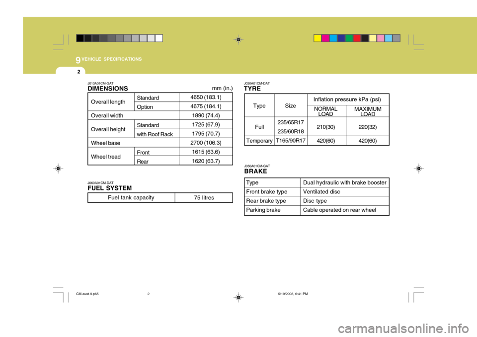
9VEHICLE SPECIFICATIONS
2
4650 (183.1) 4675 (184.1)1890 (74.4) 1725 (67.9)1795 (70.7)
2700 (106.3) 1615 (63.6) 1620 (63.7)
J010A01CM-GAT DIMENSIONS
Overall length Overall width Overall height Wheel baseWheel tread
mm (in.)
Standard Option Standard with Roof Rack Front Rear
J030A01CM-DAT
TYRE
Full
Temporary Size
Type Inflation pressure kPa (psi)
235/65R17 235/60R18
T165/90R17 NORMAL
LOAD MAXIMUM
LOAD
220(32) 420(60)
210(30)420(60)
J060A01CM-DAT FUEL SYSTEM
Fuel tank capacity
75 litres
J050A01CM-GAT BRAKE
Dual hydraulic with brake booster Ventilated discDisc typeCable operated on rear wheel
TypeFront brake typeRear brake typeParking brake
CM-aust-9.p65
5/19/2008, 6:41 PM
2