Auto hold Hyundai Santa Fe 2020 Owner's Manual
[x] Cancel search | Manufacturer: HYUNDAI, Model Year: 2020, Model line: Santa Fe, Model: Hyundai Santa Fe 2020Pages: 557, PDF Size: 19.29 MB
Page 16 of 557
I
IN
N S
ST
T R
R U
U M
M E
EN
N T
T
P
P A
A N
N E
EL
L
O
O V
VE
ER
R V
V I
IE
E W
W
(
( I
I)
)
The actual shape may differ from the illustration.
1-5
Your vehicle at a glance
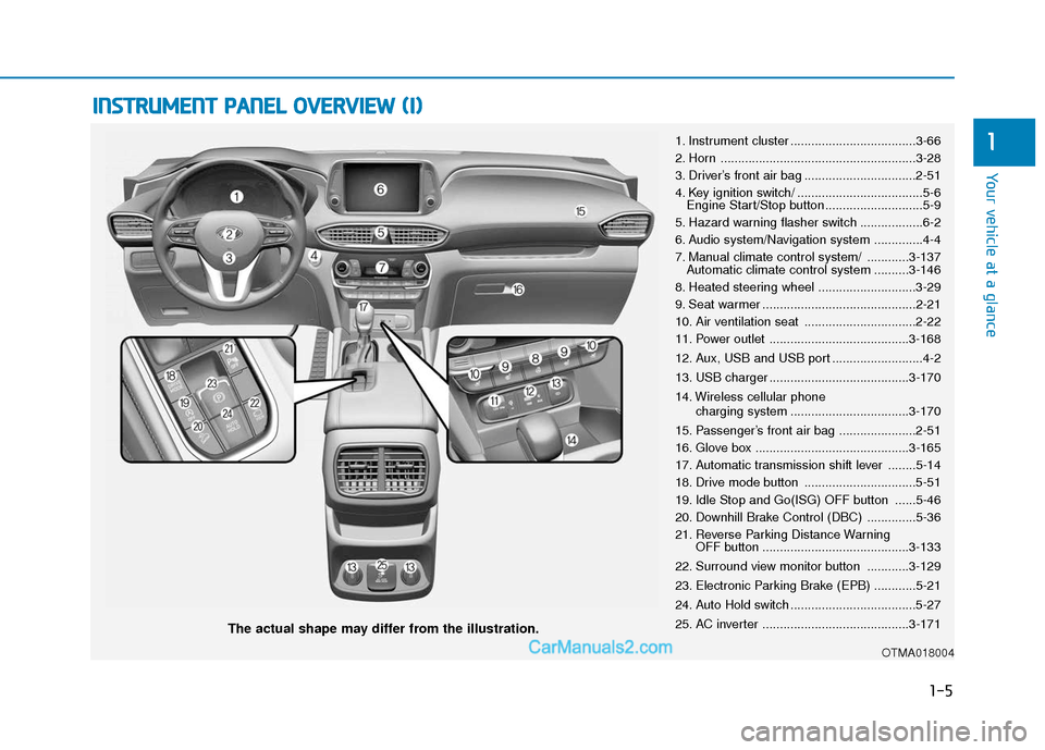
11. Instrument cluster ....................................3-66
2. Horn ........................................................3-28
3. Driver’s front air bag ................................2-51
4. Key ignition switch/ ....................................5-6
Engine Start/Stop button ............................5-9
5. Hazard warning flasher switch ..................6-2
6. Audio system/Navigation system ..............4-4
7. Manual climate control system/ ............3-137 Automatic climate control system ..........3-146
8. Heated steering wheel ............................3-29
9. Seat warmer ............................................2-21
10. Air ventilation seat ................................2-22
11. Power outlet ........................................3-168
12. Aux, USB and USB port ..........................4-2
13. USB charger ........................................3-170
14. Wireless cellular phone charging system ..................................3-170
15. Passenger’s front air bag ......................2-51
16. Glove box ............................................3-165
17. Automatic transmission shift lever ........5-14
18. Drive mode button ................................5-51
19. Idle Stop and Go(ISG) OFF button ......5-46
20. Downhill Brake Control (DBC) ..............5-36
21. Reverse Parking Distance Warning OFF button ..........................................3-133
22. Surround view monitor button ............3-129
23. Electronic Parking Brake (EPB) ............5-21
24. Auto Hold switch ....................................5-27
25. AC inverter ..........................................3-171
OTMA018004
Page 60 of 557
2-42
Safety system of your vehicle
After selecting a proper child seat for
your child, check to make sure it fits
properly in your vehicle. Follow the
instructions provided by the manu-
facturer when installing the child
seat. Note these general steps when
installing the seat to your vehicle:
Properly secure the child
restraint to the vehicle. All child
restraints must be secured to the
vehicle with the lap part of a
lap/shoulder belt or with the
LATCH system. If using the
lap/shoulder belt for your child
restraint, the convertible locking
retractor should be pulled all the
way out to engage the "automatic
locking" mode. (See page 2-45.)
Make sure the child restraint is
firmly secured. After installing a
child restraint to the vehicle, push
and pull the seat forward-and-
back and side-to-side to verify that
it is securely attached to the seat.
A child restraint secured with a
seat belt should be installed as
firmly as possible. However, some
side-to-side movement can be
expected.
Secure the child in the child
restraint. Make sure the child is
properly strapped in the child
restraint according to the manu-
facturer instructions.
Lower Anchors and Tether for Children (LATCH System)
The LATCH system holds a child
restraint during driving and in an acci-
dent. This system is designed to
make installation of the child restraint
easier and reduce the possibility of
improperly installing your child
restraint. The LATCH system uses
anchors in the vehicle and attach-
ments on the child restraint. The
LATCH system eliminates the need
to use seat belts to secure the child
restraint to the rear seats.
Lower anchors are metal bars built
into the vehicle. There are two lower
anchors for each LATCH seating
position that will accommodate a
child restraint with lower attachments.
To use the LATCH system in your
vehicle, you must have a child
restraint with LATCH attachments.
The child seat manufacturer will pro-
vide you with instructions on how to
use the child seat with its attachments
for the LATCH lower anchors.
A child restraint in a closed
vehicle can become very hot. To
prevent burns, check the seat-
ing surface and buckles before
placing your child in the child
restraint.
CAUTION
Page 66 of 557
2-48
Safety system of your vehicle
5. Remove as much slack from the belt as possible by pushing down
on the child restraint system while
feeding the shoulder belt back into
the retractor.
6. Push and pull on the child restraint system to confirm that the seat
belt is holding it firmly in place. If it
is not, release the seat belt and
repeat steps 2 through 6.
7. Double check that the retractor is in the "Automatic Locking" mode
by attempting to pull more of the
seat belt out of the retractor. If you
cannot, the retractor is in the
"Automatic Locking" mode.
If your CRS manufacturer instructs or
recommends you to use a tether
anchor with the lap/shoulder belt,
refer to the previous pages for more
information. When the seat belt is allowed to
retract to its fully stowed position,
the retractor will automatically
switch from the "Automatic
Locking" mode to the emergency
lock mode for normal adult usage.
To remove the child restraint, press
the release button on the buckle and
then pull the lap/shoulder belt out of
the restraint and allow the seat belt
to retract fully.
NOTICE
If the retractor is not in the
"Automatic Locking" mode, the
child restraint can move when
your vehicle turns or stops sud-
denly. A child can be seriously
injured or killed if the child
restraint is not properly anchored
in the car, including manually
pulling the seat belt all the way
out to shift the rectractor to the
"Automatic Locking" mode.
WARNING
Page 75 of 557
2-57
Safety system of your vehicle
2
You can take steps to help reduce
the risk of being injured by an inflat-
ing air bag. The greatest risk is sitting
too close to the air bag. An air bag
needs about 10 inches (25 cm) of
space to inflate. NHTSA recom-
mends that drivers allow at least 10
inches (25 cm) between the center of
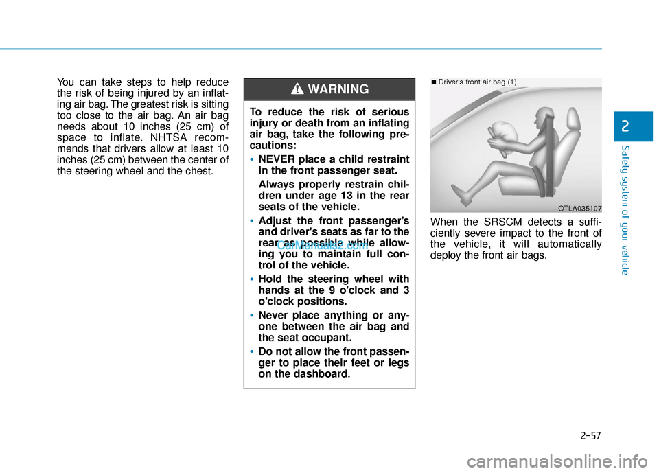
the steering wheel and the chest.When the SRSCM detects a suffi-
ciently severe impact to the front of
the vehicle, it will automatically
deploy the front air bags.
OTLA035107
■Driver's front air bag (1)
To reduce the risk of serious
injury or death from an inflating
air bag, take the following pre-
cautions:
NEVER place a child restraint
in the front passenger seat.
Always properly restrain chil-
dren under age 13 in the rear
seats of the vehicle.
Adjust the front passenger’s
and driver's seats as far to the
rear as possible while allow-
ing you to maintain full con-
trol of the vehicle.
Hold the steering wheel with
hands at the 9 o'clock and 3
o'clock positions.
Never place anything or any-
one between the air bag and
the seat occupant.
Do not allow the front passen-
ger to place their feet or legs
on the dashboard.
WARNING
Page 91 of 557
LCD Display ...........................................................3-91
LCD Display Control ........................................................3-91
LCD Display Modes .........................................................3-92
Trip Computer .....................................................3-106
Head Up Display (HUD).....................................3-110
Lighting................................................................3-112
Exterior Lights ...............................................................3-112
Interior Lights ................................................................3-120
Welcome System ...........................................................3-123
Wipers And Washers .........................................3-124
Front Windshield Wipers .............................................3-124
Front Windshield Washers ..........................................3-126
Rear Window Wiper and Washer..............................3-127
Driver Assist System .........................................3-128
Rear view monitor ........................................................3-128
Surround View Monitoring .........................................3-129
Blind-spot View Monitor system ..............................3-131
Reverse Parking Distance Warning system............3-133
Manual Climate Control System.......................3-137
Heating and Air Conditioning .....................................3-138
System Operation .........................................................3-142
System Maintenance....................................................3-144
Automatic Climate Control System ..................3-146
Automatic Temperature Control Mode ....................3-147
Manual Temperature Control Mode .........................3-148
System Operation .........................................................3-155
System Maintenance....................................................3-156
Windshield Defrosting and Defogging ............3-158
Auto Defogging System ..............................................3-160
Rear Window Defroster ..............................................3-162
Climate Control Additional Features ...............3-163
Cluster ionizer ................................................................3-163
Automatic Ventilation ...................................................3-163
Sunroof Inside Air Recirculation ...............................3-164
Auto comfort control ...................................................3-164
Storage Compartment .......................................3-165
Center Console Storage ..............................................3-165
Glove Box ........................................................................\
3-165
Sunglass Holder.............................................................3-166
Tray......................................................................\
.............3-166
Luggage Tray .................................................................3-167
3
Page 94 of 557
3-5
Convenient features of your vehicle
3
The Two Press Unlock feature can
also be enabled or disabled by press-
ing the door lock and unlock buttons
simultaneously on the Key FOB:
Press and hold both the Door Lock
button and the Door Unlock button
simultaneously until the hazard
warning lights blink.
This will enable or disable the Two
Press Unlock feature. Repeat this
procedure to enable/disable the
mode again.
Information
After unlocking the doors, the doors
will automatically relock after 30 sec-
onds unless a door is opened.
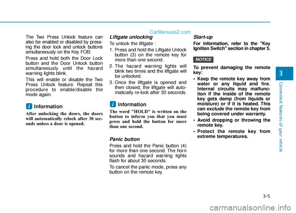
Liftgate unlocking
To unlock the liftgate :
1. Press and hold the Liftgate Unlockbutton (3) on the remote key for
more than one second.
2. The hazard warning lights will blink two times and the liftgate will
be unlocked.
3. Once the liftgate is opened and then closed, the liftgate will auto-
matically re-lock after 30 seconds.
Information
The word "HOLD" is written on the
button to inform you that you must
press and hold the button for more
than one second.
Panic button
Press and hold the Panic button (4)
for more than one second. The horn
sounds and hazard warning lights
flash for about 30 seconds.
To cancel the panic mode, press any
button on the remote key.
Start-up
For information, refer to the "Key
Ignition Switch" section in chapter 5.
To prevent damaging the remote
key:
• Keep the remote key away fromwater or any liquid and fire.
Internal circuits may malfunc-
tion if the inside of the remote
key gets damp (from liquids or
moisture) or if it is heated. This
can exclude the remote key from
being covered under warranty.
Avoid dropping or throwing the remote key.
Protect the remote key from extreme temperatures.
NOTICE
ii
Page 98 of 557
3-9
Convenient features of your vehicle
3
Two Press Unlock Feature
The priority for unlocking the driver
door only, or unlocking all the doors
with one press may be adjusted in
the User Settings mode in the cluster
LCD display.
The Two Press Unlock feature, when
enabled, will require the user to
press the door unlock button once for
driver door only and twice for unlock-
ing all the doors.
Select or Deselect the Two Press
Unlock feature in the User Settings
mode in the cluster LCD display. The
option can be found under the follow-
ing menu:
User Settings ➞Door ➞Two Press
Unlock The Two Press Unlock feature can
also be enabled or disabled by
pressing the door lock and unlock
buttons simultaneously on the Key
FOB:
Press and hold both the Door Lock
button and the Door Unlock button
simultaneously until the hazard
warning lights blink.
This will enable or disable the Two
Press Unlock feature. Repeat this
procedure to enable/disable the
mode again.
Information
• The door handle buttons will only
operate when the smart key is with-
in 28-40 inches (0.7~1m) from the
outside door handle.
• Either the driver or front passenger door can be opened with the door
handle button when the smart key
is within this range.
• If you press the front passenger outside door handle with the smart
key in your possession, all the doors
will unlock.
Opening the liftgate
Non-power liftgate
To unlock and open the liftgate:
1. Make sure you have the smart keyin your possession.
2. Press either the liftgate handle release switch on the vehicle or
press and hold the Liftgate Unlock
button on the smart key for more
than one second. The hazard
warning lights will blink two times
and the liftgate latch will unlock.
3. Once the liftgate is opened and then closed, the liftgate will auto-
matically re-lock after 30 seconds.
Information
• The liftgate handle switch will onlyoperate when the smart key is with-
in 28 inches (0.7 m) from the lift-
gate handle.
• The Liftgate Unlock button (3) will only unlock the liftgate. It will not
release the latch and open the lift-
gate automatically. If the Liftgate
Unlock button is used, someone
must still press the liftgate handle
switch to open the liftgate.
i
i
Page 99 of 557
3-10
Convenient features of your vehicle
Power liftgate
To unlock and open the liftgate:
1. Make sure you have the smart keyin your possession.
2. Press either the liftgate handle release switch on the vehicle or
press and hold the Liftgate Unlock
button on the smart key for more
than one second. The hazard
warning lights will blink two times
and the liftgate latch will open.
3. Once the liftgate is opened and then closed, the liftgate will auto-
matically re-lock after 30 seconds.
Information
The liftgate handle switch will only
operate when the smart key is within
28 inches (0.7 m) from the liftgate
handle.
Panic button
Press and hold the Panic button (4)
for more than one second. The horn
sounds and hazard warning lights
blink for about 30 seconds. To cancel
the panic mode, press any button on
the Smart Key.
Start-up
You can start the vehicle without
inserting the key.
For information, refer to the
"Engine Start/Stop Button" sec-
tion in chapter 5.
To prevent damaging the smart key:
Keep the smart key in a cool, dryplace to avoid damage or mal-
function. Exposure to moisture
or high temperature may cause
the internal circuit of the smart
key to malfunction which may
not be covered under warranty.
Avoid dropping or throwing the smart key.
Protect the smart key from extreme temperatures.
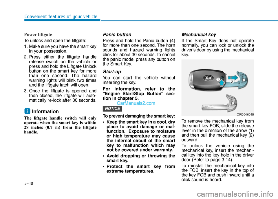
Mechanical key
If the Smart Key does not operate
normally, you can lock or unlock the
driver's door by using the mechanical
key.
To remove the mechanical key from
the smart key FOB, slide the release
lever in the direction of the arrow (1)
and then pull the mechanical key (2)
outward.
To unlock the vehicle using the
mechanical key, insert the mechani-
cal key into the key hole in the driver
door (Refer to page 3-14).
To reinstall the mechanical key into
the FOB, insert the key in the top of
the key FOB and push inward until a
click sound is heard.
NOTICEiOPD046045
Page 121 of 557
3-32
Convenient features of your vehicle
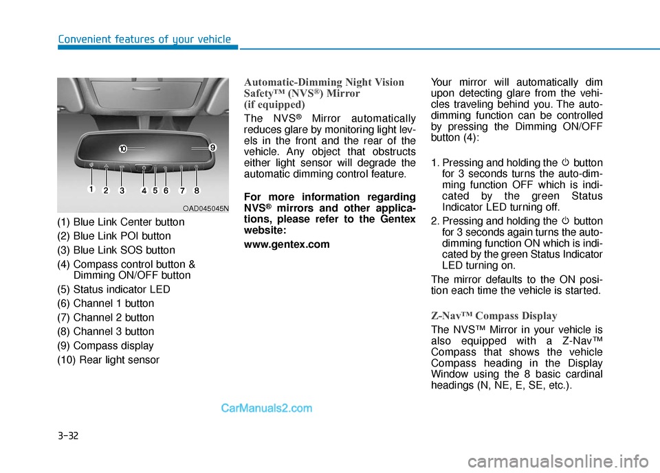
(1) Blue Link Center button
(2) Blue Link POI button
(3) Blue Link SOS button
(4) Compass control button & Dimming ON/OFF button
(5) Status indicator LED
(6) Channel 1 button
(7) Channel 2 button
(8) Channel 3 button
(9) Compass display
(10) Rear light sensor
Automatic-Dimming Night Vision
Safety™ (NVS®) Mirror
(if equipped)
The NVS®Mirror automatically
reduces glare by monitoring light lev-
els in the front and the rear of the
vehicle. Any object that obstructs
either light sensor will degrade the
automatic dimming control feature.
For more information regarding
NVS
®mirrors and other applica-
tions, please refer to the Gentex
website:
www.gentex.com Your mirror will automatically dim
upon detecting glare from the vehi-
cles traveling behind you. The auto-
dimming function can be controlled
by pressing the Dimming ON/OFF
button (4):
1. Pressing and holding the button
for 3 seconds turns the auto-dim-
ming function OFF which is indi-
cated by the green Status
Indicator LED turning off.
2. Pressing and holding the button for 3 seconds again turns the auto-
dimming function ON which is indi-
cated by the green Status Indicator
LED turning on.
The mirror defaults to the ON posi-
tion each time the vehicle is started.
Z-Nav™ Compass Display
The NVS™ Mirror in your vehicle is
also equipped with a Z-Nav™
Compass that shows the vehicle
Compass heading in the Display
Window using the 8 basic cardinal
headings (N, NE, E, SE, etc.).
OAD045045N
Page 126 of 557
3-37
Convenient features of your vehicle
3
Gate operator & Canadian program-ming
During programming, your handheld
transmitter may automatically stop
transmitting. Continue to press the
Integrated HomeLink
®Wireless
Control System button (note steps 2
through 3 in the Programming portion
of this document) while you press
and re-press ("cycle") your handheld
transmitter every two seconds until
the frequency signal has been
learned. The indicator light will flash
slowly and then rapidly after several
seconds upon successful training.
Operating HomeLink®
To operate, simply press and release
the programmed HomeLink®button.
Activation will now occur for the
trained device (i.e. garage door
opener, gate operator, security sys-
tem, entry door lock, home/office
lighting, etc.). For convenience, the
hand-held transmitter of the device
may also be used at any time.
Reprogramming a single HomeLink®
button
To program a device to HomeLink®
using a HomeLink®button previously
trained, follow these steps:
1. Press and hold the desired HomeLink
®button. DO NOT
release the button.
2. The indicator light will begin to flash after 20 seconds. Without releasing
the HomeLink
®button, proceed
with "Programming" step 2.
For questions or comments, contact
HomeLink
®at www.homelink.comor
1-800-355-3515.
Erasing HomeLink®buttons
Individual buttons cannot be erased.
However, to erase all three pro-
grammed buttons:
1. Press and hold the two outer HomeLink
®buttons until the indi-
cator light begins to flash after 10
seconds.
2. Release both buttons. Do not hold for longer than 20 seconds.
The Integrated HomeLink
®Wireless
Control System is now in the training
(learn) mode and can be pro-
grammed at any time following the
appropriate steps in the
Programming chapters above.
NVS
®is a registered trademark and
Z-Nav™ is a trademark of the Gentex
Corporation, Zeeland, Michigan.
HomeLink
®is a registered trademark
owned by Johnson Controls,
Incorporated, Milwaukee, Wisconsin.
FCC ID: NZLTLMHL4
IC: 4112A-TLMHL4