engine HYUNDAI SANTA FE 2021 Owner's Manual
[x] Cancel search | Manufacturer: HYUNDAI, Model Year: 2021, Model line: SANTA FE, Model: HYUNDAI SANTA FE 2021Pages: 636, PDF Size: 81.2 MB
Page 83 of 636
03
3-51
During a moderate to severe frontal
collision, sensors will detect the
vehicle’s rapid deceleration. If the rate of
deceleration is high enough, the control
unit will inflate the front air bags, at the
time and with the force needed.
The front air bags help protect the driver
and front passenger by responding to
frontal impacts in which seat belts alone
cannot provide adequate restraint. When
needed, the side air bags help provide
protection in the event of a side impact
or rollover by supporting the side upper
body area.
• Air bags are activated (able to
inflate if necessary) only when the
Engine Start/Stop button is in the
ON or START position, and it can be
activated within about 3 minutes after
the engine is turned off.
• Air bags inflate in the event of certain
frontal or side collisions to help
protect the occupants from serious
physical injury.
• There is no single speed at which the
air bags will inflate. Generally, air bags
are designed to inflate based upon the
severity of a collision and its direction.
These two factors determine whether
the sensors produce an electronic
deployment/inflation signal.
• The front air bags will completely
inflate and deflate in an instant. It is
virtually impossible for you to see the
air bags inflate during an accident. It is
much more likely that you will simply
see the deflated air bags hanging out
of their storage compartments after
the collision. •
In addition to inflating in serious side
collisions, vehicles equipped with a
rollover sensor, side and/or curtain air
bags will inflate if the sensing system
detects a rollover.
When a rollover is detected, curtain
air bags will remain inflated longer to
help provide protection from ejection,
especially when used in conjunction
with the seat belts. (if equipped with a
rollover sensor)
• To help provide protection, the air
bags must inflate rapidly. The speed
of air bag inflation is a consequence
of extremely short time in which
to inflate the air bag between the
occupant and the vehicle structures
before the occupant impacts those
structures. This speed of inflation
reduces the risk of serious or
lifethreatening injuries and is thus a
necessary part of air bag design.
However, the rapid air bag inflation
can also cause injuries which can
include facial abrasions, bruises and
broken bones because the inflation
speed also causes the air bags to
expand with a great deal of force.
• There are even circumstances under
which contact with the air bag can
cause fatal injuries, especially if the
occupant is positioned excessively
close to the air bag.
You can take steps to reduce the risk
of being injured by an inflating air bag.
The greatest risk is sitting too close to
the air bag. An air bag needs about 10
in. (25 cm) of space to inflate. NHTSA
recommends that drivers allow at least
10 in. (25 cm) between the center of the
steering wheel and the chest.
Page 91 of 636
03
3-59
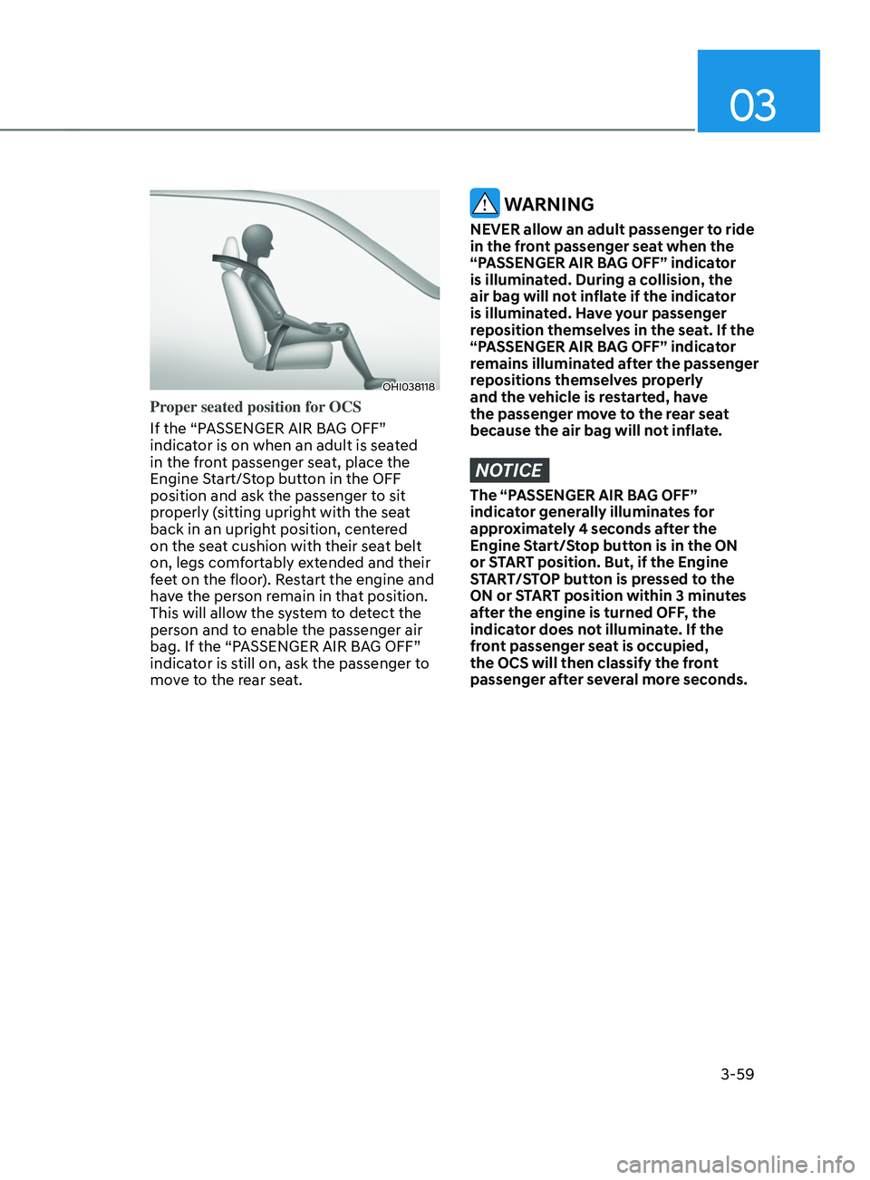
OHI038118
Proper seated position for OCS
If the “PASSENGER AIR BAG OFF”
indicator is on when an adult is seated
in the front passenger seat, place the
Engine Start/Stop button in the OFF
position and ask the passenger to sit
properly (sitting upright with the seat
back in an upright position, centered
on the seat cushion with their seat belt
on, legs comfortably extended and their
feet on the floor). Restart the engine and
have the person remain in that position.
This will allow the system to detect the
person and to enable the passenger air
bag. If the “PASSENGER AIR BAG OFF”
indicator is still on, ask the passenger to
move to the rear seat.
WARNING
NEVER allow an adult passenger to ride
in the front passenger seat when the
“PASSENGER AIR BAG OFF” indicator
is illuminated. During a collision, the
air bag will not inflate if the indicator
is illuminated. Have your passenger
reposition themselves in the seat. If the
“PASSENGER AIR BAG OFF” indicator
remains illuminated after the passenger
repositions themselves properly
and the vehicle is restarted, have
the passenger move to the rear seat
because the air bag will not inflate.
NOTICE
The “PASSENGER AIR BAG OFF”
indicator generally illuminates for
approximately 4 seconds after the
Engine Start/Stop button is in the ON
or START position. But, if the Engine
START/STOP button is pressed to the
ON or START position within 3 minutes
after the engine is turned OFF, the
indicator does not illuminate. If the
front passenger seat is occupied,
the OCS will then classify the front
passenger after several more seconds.
Page 92 of 636
Seats & Safety System
3-60
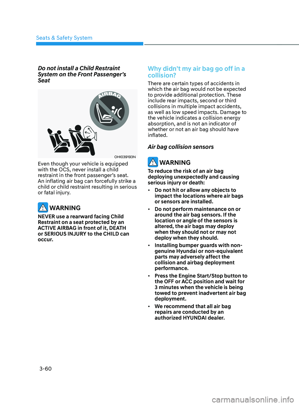
Do not install a Child Restraint
System on the Front Passenger’s
Seat
OHI039193N
Even though your vehicle is equipped
with the OCS, never install a child
restraint in the front passenger’s seat.
An inflating air bag can forcefully strike a
child or child restraint resulting in serious
or fatal injury.
WARNING
NEVER use a rearward facing Child
Restraint on a seat protected by an
ACTIVE AIRBAG in front of it, DEATH
or SERIOUS INJURY to the CHILD can
occur.
Why didn’t my air bag go off in a
collision?
There are certain types of accidents in
which the air bag would not be expected
to provide additional protection. These
include rear impacts, second or third
collisions in multiple impact accidents,
as well as low speed impacts. Damage to
the vehicle indicates a collision energy
absorption, and is not an indicator of
whether or not an air bag should have
inflated.
Air bag collision sensors
WARNING
To reduce the risk of an air bag
deploying unexpectedly and causing
serious injury or death:
• Do not hit or allow any objects to
impact the locations where air bags
or sensors are installed.
• Do not perform maintenance on or
around the air bag sensors. If the
location or angle of the sensors is
altered, the air bags may deploy
when they should not or may not
deploy when they should.
• Installing bumper guards with non-
genuine Hyundai or non-equivalent
parts may adversely affect the
collision and airbag deployment
performance.
• Press the Engine Start/Stop button to
the OFF or ACC position and wait for
3 minutes when the vehicle is being
towed to prevent inadvertent air bag
deployment.
• We recommend that all air bag
repairs are conducted by an
authorized HYUNDAI dealer.
Page 97 of 636
03
3-65
SRS care
The SRS is virtually maintenance-free
and there are no parts you can safely
service by yourself. If the SRS air bag
warning light does not illuminate when
the Engine Start/Stop button is in the
ON position, or continuously remains
on, we recommend that the system be
immediately inspected by an authorized
HYUNDAI dealer.
We recommend any work on the SRS
system, such as removing, installing,
repairing, or any work on the steering
wheel, the front passenger’s panel, front
seats and roof rails be performed by an
authorized HYUNDAI dealer. Improper
handling of the SRS system may result in
serious personal injury. WARNING
To reduce the risk of serious injury or
death take the following precautions:
• Do not attempt to modify or
disconnect the SRS components or
wiring, including the addition of any
kind of badges to the pad covers or
modifications to the body structure.
• Do not place objects over or near
the air bag modules on the steering
wheel, instrument panel, and the
front passenger’s panel above the
glove box.
• Clean the air bag pad covers with
a soft cloth moistened with plain
water. Solvents or cleaners could
adversely affect the air bag covers
and proper deployment of the
system.
• We recommend that inflated air
bags be replaced by an authorized
HYUNDAI dealer.
• If components of the air bag system
must be discarded, or if the vehicle
must be scrapped, certain safety
precautions must be observed.
We recommend that you consult
an authorized HYUNDAI dealer for
the necessary information. Failure
to follow these precautions could
increase the risk of personal injury.
Page 98 of 636
Seats & Safety System
3-66
Additional safety precautions
Passengers should not move out of
or change seats while the vehicle is
moving. A passenger who is not wearing
a seat belt during a crash or emergency
stop can be thrown against the inside of
the vehicle, against other occupants, or
be ejected from the vehicle.
Do not use any accessories on seat
belts. Devices claiming to improve
occupant comfort or reposition the seat
belt can reduce the protection provided
by the seat belt and increase the chance
of serious injury in a crash.
Do not modify the front seats.
Modification of the front seats could
interfere with the operation of the
supplemental restraint system sensing
components or side air bags.
Do not place items under the front
seats. Placing items under the front seats
could interfere with the operation of the
supplemental restraint system sensing
components and wiring harnesses.
Do not cause impact to the doors.
Impact to the doors when the Engine
Start/Stop button is in the ON or START
position may cause the air bags to
inflate.
Modifications to accommodate
disabilities. If you require modification
to your vehicle to accommodate
a disability, contact the HYUNDAI
Customer Connect Center at 800-633-
5151.
Adding equipment to or modifying
your air bag equipped vehicle
If you modify your vehicle by changing
your vehicle’s frame, bumper system,
front end or side sheet metal or ride
height, this may affect the operation of
your vehicle’s air bag system.
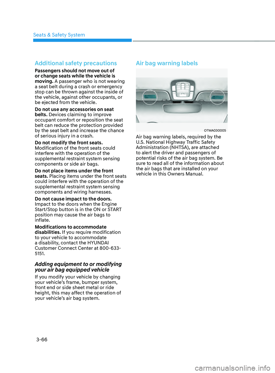
Air bag warning labels
OTMA030005
Air bag warning labels, required by the
U.S. National Highway Traffic Safety
Administration (NHTSA), are attached
to alert the driver and passengers of
potential risks of the air bag system. Be
sure to read all of the information about
the air bags that are installed on your
vehicle in this Owners Manual.
Page 99 of 636
Instrument cluster
Instrument cluster ........................................................................\
....................4-4Instrument cluster control ........................................................................\
...................4-5
Instrumen t panel illumination ........................................................................\
........... 4-5
Gauges and me
ters
........................................................................\
.............................. 4-5
Speedome
ter
........................................................................\
..................................... 4-5
T
achometer
........................................................................\
.....................................
...4-5
Engine coolant temperature gauge
........................................................................\
. 4-6
Fuel gauge ........................................................................\
.....................................
....4-6
Outside temperature gauge
........................................................................\
.............. 4
-7
Odometer
........................................................................\
.....................................
.....4-8
Distance to empty
........................................................................\
............................ 4-8
F
uel economy (for 12.3-inch cluster)
...................................................................... 4-9
T
ransmission shift indicator
........................................................................\
................ 4-9
A
utomatic transmission / Dual clutch transmission shift indicator
..................... 4-9
W
arning and indicator lights
........................................................................\
............. 4-
10
Seat belt warning light
........................................................................\
.................... 4-
10
Air bag warning light
........................................................................\
....................... 4-
10
Parking brake & Brake fluid warning light
.............................................................. 4-10
An
ti-lock Brake System (ABS) warning light
........................................................... 4-
11
Electronic Brake Force Distribution (EBD) system warning light
.......................... 4-
11
Electric Power Steering (EPS) warning light
.......................................................... 4-
12
Charging system warning light
........................................................................\
....... 4-
12
Engine oil pressure warning light
........................................................................\
... 4-
13
Low fuel level warning light
........................................................................\
............ 4-
13
Malfunction Indicator Lamp (MIL)
........................................................................\
.. 4-13
Exhaus
t system (GPF) warning light (for gasoline engine)
................................... 4-
14
Electronic Parking Brake (EPB) warning light
........................................................ 4-
14
AUTO HOLD indicator light
........................................................................\
............. 4-
15
Low tire pressure warning light
........................................................................\
...... 4-
15
Forward Safety warning light
........................................................................\
.......... 4-16
Lane Sa
fety indicator light
........................................................................\
.............. 4-
16
4 Wheel Drive (4WD) warning light
........................................................................\
4-
16
4 Wheel Drive (4WD) LOCK Indicator Light
............................................................ 4-17
LED headligh
t warning light
........................................................................\
............. 4-
17
Icy road warning light
........................................................................\
...................... 4-
18
Electronic Stability Control (ESC) indicator light
................................................... 4-
18
Electronic Stability Control (ESC) OFF indicator light
........................................... 4-
18
Immobilizer Indicator Light (without smart key)
.................................................. 4-
19
Immobilizer Indicator Light (with smart key)
......................................................... 4-
19
Downhill Brake Control (DBC) indicator light
........................................................
4-20
4. Instrument cluster
4
Page 100 of 636
AUTO STOP indicator light ........................................................................\
..............4-20
T urn signal indicator light ........................................................................\
................. 4-
21
High beam indicator light
........................................................................\
................ 4-
21
High Beam Assist indicator light
........................................................................\
...... 4-
21
Cruise Indicator Light
........................................................................\
....................... 4-
21
SPORT Mode Indicator Light
........................................................................\
........... 4-
22
ECO Mode Indicator Light
........................................................................\
............... 4-
22
SMART Mode Indicator Light
........................................................................\
.......... 4-22
Mas
ter warning light
........................................................................\
........................ 4-
22
LCD display messages
........................................................................\
....................... 4-
23
Shift to P (for smart key system)
........................................................................\
..... 4-
23
Low key battery (for smart key system).................................................................. 4-23
Press START button while turning wheel (for smart key system)
......................... 4-
23
Check steering wheel lock system
(for smart key system)
........................................................................\
..................... 4-
23
Press brake pedal to start engine (for smart key system)
.................................... 4-
23
Key not in vehicle (for smart key system)
............................................................... 4-23
K
ey not detected (for smart key system)................................................................ 4-23
Press START button again (for smart key system)
................................................ 4-
23
Press START button with key (for smart key system)
........................................... 4
-24
Check BRAKE SWITCH fuse (for smart key system)
............................................. 4
-24
Shift to P or N to start engine (for smart key system)
.......................................... 4
-24
Battery discharging due to external electrical devices
......................................... 4
-24
Door, Hood, Liftgate open indicator
....................................................................... 4-25
Sunr
oof open indicator
........................................................................\
.................... 4-
25
Low tire pressure
........................................................................\
............................. 4-
25
Lights
........................................................................\
................................................ 4-
26
Wiper
........................................................................\
.....................................
...........4-26
Low washer fluid
........................................................................\
.............................. 4-
26
Low fuel
........................................................................\
.....................................
.......4-26
Low engine oil
........................................................................\
.................................. 4-
26
Engine overheated / Engine has overheated
......................................................... 4-
27
Check exhaust system
........................................................................\
..................... 4-
27
Check headlight
........................................................................\
............................... 4-
27
Check turn signal
........................................................................\
............................. 4-
27
Check headlamp LED
........................................................................\
...................... 4-
27
Check Forward Collision-Avoidance Assist system
............................................... 4-
28
Check Lane Keeping Assist system
........................................................................\
4-28
Check Blind-
Spot Collision Warning system..........................................................4-28
Check Driver Attention Warning system
................................................................ 4-
28
Check High Beam Assist system
........................................................................\
..... 4-
28
Check Smart Cruise Control system
....................................................................... 4-28
4
Page 102 of 636
4-4
Instrument cluster
„„4.2-inch
„„12.3-inch
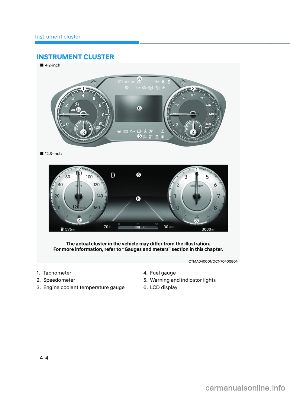
The actual cluster in the vehicle may differ from the illustration.
For more information, refer to “Gauges and meters” section in this chapter.
OTMA040001/OCN7040080N
1. Tachometer
2.
Speedomet
er
3.
Engine coolan
t temperature gauge 4. Fuel gauge
5.
Warning and indica
tor lights
6.
LCD displa
y
INSTRUMENT CLUSTER
Page 103 of 636
04
4-5
Instrument cluster control
Instrument panel illumination
When the vehicle’s parking lights or
headlamps are on, press the illumination
control switch to adjust the brightness of
the instrument panel illumination.
When pressing the illumination control
switch, the interior switch illumination
intensity also adjusted.
You can adjust the brightness of the
instrument panel illumination form the
User Settings Mode on the LCD display
when
the ignition s
witch
is on (‘Ligh
ts
→ Illumination
’). When the vehicle’s parking
lights or headlamps are on, interior
switch illumination intensity and mood
lamps are also adjusted.
If your vehicle is equipped with
additional navigation, please refer
to the infotainment system manual
separately supplied.
WARNING
Never adjust the instrument cluster
while driving. This could result in loss
of control and lead to an accident that
may cause death, serious injury, or
vehicle damage.
• The brightness of the instrument
panel illumination is displayed.
• If the brightness reaches to the
maximum or minimum level, a chime
will sound.
Gauges and meters
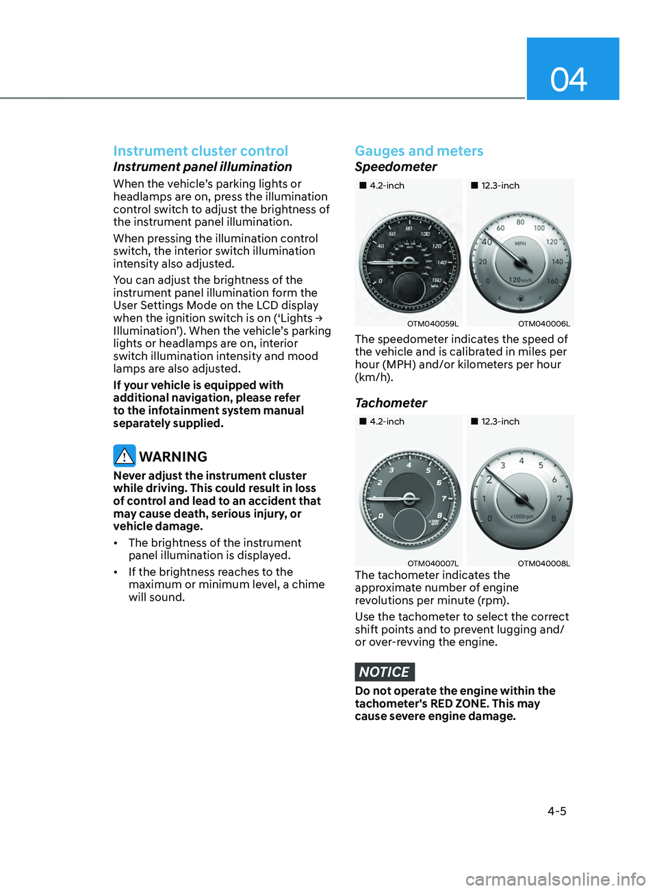
Speedometer
„„4.2-inch „„12.3-inch
OTM040059LOTM040006L
The speedometer indicates the speed of
the vehicle and is calibrated in miles per
hour (MPH) and/or kilometers per hour
(km/h).
Tachometer
„„4.2-inch„„12.3-inch
OTM040007LOTM040008LThe tachometer indicates the
approximate number of engine
revolutions per minute (rpm).
Use the tachometer to select the correct
shift points and to prevent lugging and/
or over-revving the engine.
NOTICE
Do not operate the engine within the
tachometer's RED ZONE. This may
cause severe engine damage.
Page 104 of 636
Instrument cluster
4-6
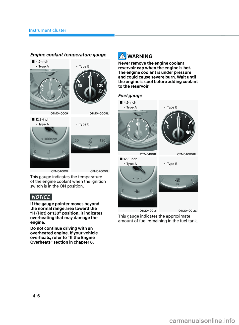
Engine coolant temperature gauge
„„4.2-inch„•Type A„•Type B
OTM040009OTM040009L
„„12.3-inch„•Type A„•Type B
OTM040010OTM040010L
This gauge indicates the temperature
of the engine coolant when the ignition
switch is in the ON position.
NOTICE
If the gauge pointer moves beyond
the normal range area toward the
“H (Hot) or 130” position, it indicates
overheating that may damage the
engine.
Do not continue driving with an
overheated engine. If your vehicle
overheats, refer to “If the Engine
Overheats” section in chapter 8.
WARNING
Never remove the engine coolant
reservoir cap when the engine is hot.
The engine coolant is under pressure
and could cause severe burn. Wait until
the engine is cool before adding coolant
to the reservoir.
Fuel gauge
„„4.2-inch„•Type A„•Type B
OTM040011OTM0400011L
„„12.3-inch„•Type A„•Type B
OTM040012OTM040012L
This gauge indicates the approximate
amount of fuel remaining in the fuel tank.