mode button HYUNDAI SANTA FE 2021 Owners Manual
[x] Cancel search | Manufacturer: HYUNDAI, Model Year: 2021, Model line: SANTA FE, Model: HYUNDAI SANTA FE 2021Pages: 636, PDF Size: 81.2 MB
Page 19 of 636
2-5
02
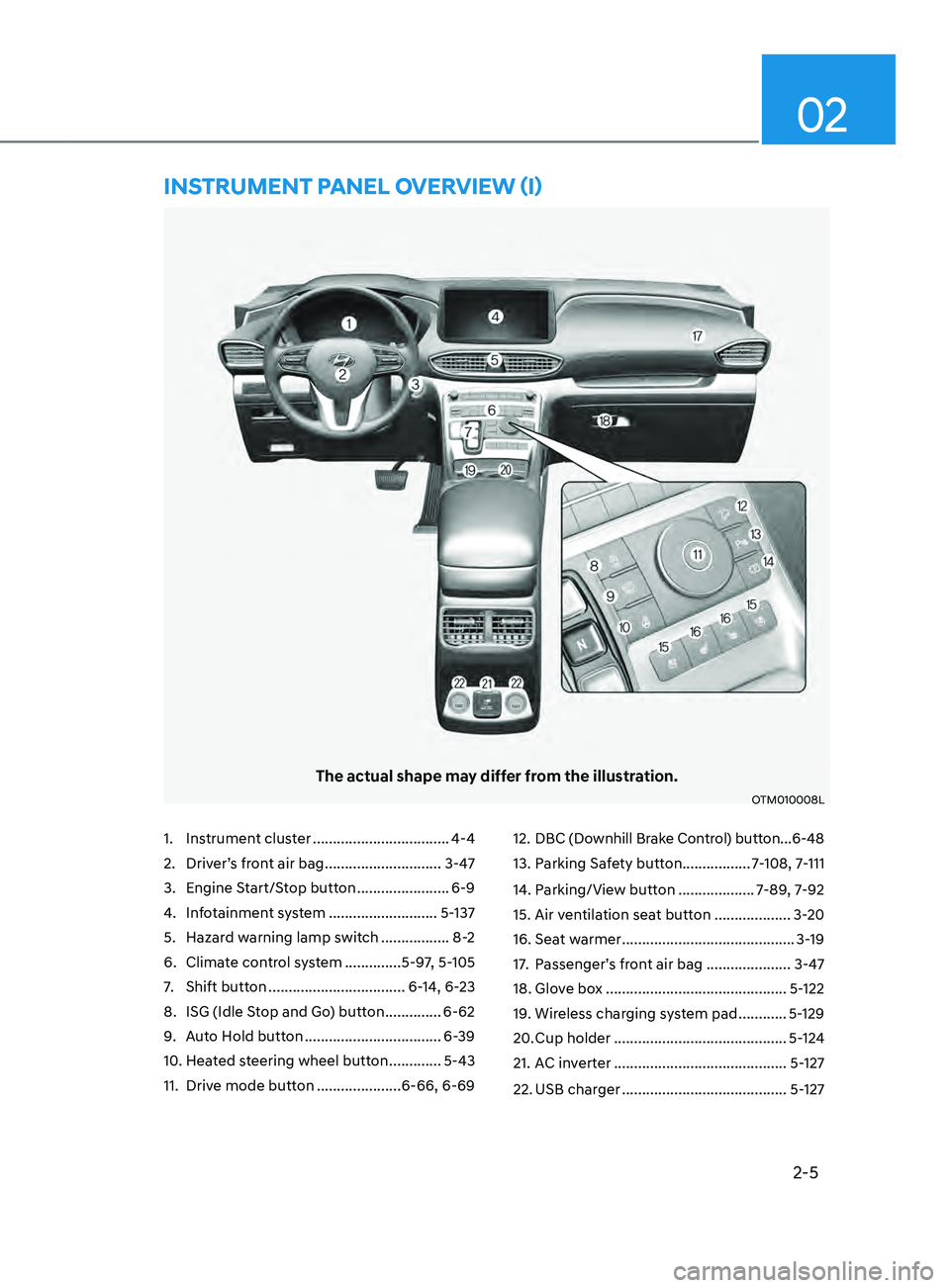
1. Instrument cluster ..................................4-4
2.
Driver’
s front air bag
............................. 3-4
7
3.
Engine S
tart/Stop button
....................... 6-9
4.
Inf
otainment system
........................... 5-
137
5.
Hazard w
arning lamp switch
.................8
-2
6.
Climat
e control system
..............5-9
7, 5-105
7.
Shift button .................................. 6-
14, 6-23
8.
ISG (Idle S
top and Go) button
..............6-62
9.
Aut
o Hold button
.................................. 6-
39
10.
Hea
ted steering wheel button
............. 5-43
11.
Drive mode butt
on
.....................6-66, 6-69 12.
DBC (Downhill Br
ake Control) button ...
6-48
13.
Parking Sa
fety button
.................7
-108, 7-111
14.
Parking/Vie
w button
...................7
-89, 7-92
15.
Air ven
tilation seat button
...................3-
20
16.
Seat w
armer
...........................................3-
19
17.
Passenger’
s front air bag
.....................
3-47
18.
Glov
e box
.............................................5-
122
19.
Wireless char
ging system pad
............5-
129
20.
Cup holder ........................................... 5-
124
21.
AC in
verter
...........................................5-
127
22.
USB charger ......................................... 5-
127
The actual shape may differ from the illustration.
OTM010008L
InsTRUmEnT pAnEL OVERVIEW (I)
Page 59 of 636
03
3-27
Rear Seat Belt – Passenger’s 3point
system with convertible locking
retractor
This type of seat belt combines the
features of both an emergency locking
retractor seat belt and an automatic
locking retractor seat belt. Convertible
retractor type seat belts are installed
in the rear seat positions to help
accommodate the installation of child
restraint systems. Although a convertible
retractor is also installed in the front
passenger seat position, NEVER place
any infant/child restraint system in the
front seat of the vehicle.
To fasten your seat belt:
Pull the seat belt out of the retractor
and insert the metal tab into the buckle.
There will be an audible “click” when
the tab locks into the buckle. When
not securing a child restraint, the seat
belt operates in the same way as the
driver’s seat belt (Emergency Locking
Retractor Type). It automatically adjusts
to the proper length only after the lap
belt portion of the seat belt is adjusted
manually so that it fits snugly across your
hips.
When the seat belt is fully extended from
the retractor to allow the installation of
a child restraint system, the seat belt
operation changes to allow the belt to
retract, but not to extend (Automatic
Locking Retractor Type). Refer to the
“Using a Child Restraint System” section
in this chapter.
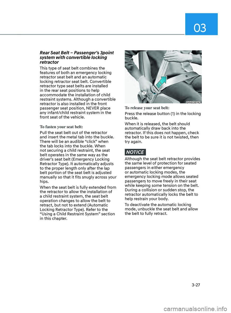
OHI038142
To release your seat belt:
Press the release button (1) in the locking
buckle.
When it is released, the belt should
automatically draw back into the
retractor. If this does not happen, check
the belt to be sure it is not twisted, then
try again.
NOTICE
Although the seat belt retractor provides
the same level of protection for seated
passengers in either emergency
or automatic locking modes, the
emergency locking mode allows seated
passengers to move freely in their seat
while keeping some tension on the belt.
During a collision or sudden stop, the
retractor automatically locks the belt to
help restrain your body.
To deactivate the automatic locking
mode, unbuckle the seat belt and allow
the belt to fully retract.
Page 75 of 636
03
3-43
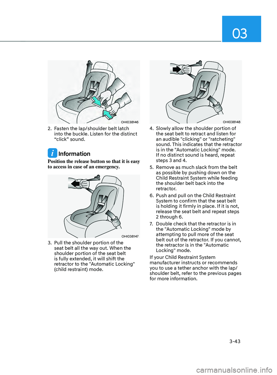
OHI038146
2. Fasten the lap/shoulder belt latch
into the buckle. Listen for the distinct
“click” sound.
Information
Position the release button so that it is easy
to access in case of an emergency.
OHI038147
3. Pull the shoulder portion of the
sea t belt all the way out. When the
shoulder portion of the seat belt
is fully extended, it will shift the
retractor to the "Automatic Locking"
(child restraint) mode.
OHI038148
4. Slowly allow the shoulder portion of
the sea t belt to retract and listen for
an audible "clicking" or "ratcheting"
sound. This indicates that the retractor
is in the "Automatic Locking" mode.
If no distinct sound is heard, repeat
steps 3 and 4.
5.
Remo
ve as much slack from the belt
as possible by pushing down on the
Child Restraint System while feeding
the shoulder belt back into the
retractor.
6.
Push and pull on the Child Res
traint
System to confirm that the seat belt
is holding it firmly in place. If it is not,
release the seat belt and repeat steps
2 through 6.
7.
Double check that the r
etractor is in
the "Automatic Locking" mode by
attempting to pull more of the seat
belt out of the retractor. If you cannot,
the retractor is in the "Automatic
Locking" mode.
If your Child Restraint System
manufacturer instructs or recommends
you to use a tether anchor with the lap/
shoulder belt, refer to the previous pages
for more information.
Page 76 of 636
Seats & Safety System
3-44
Information
When the seat belt is allowed to retract to
its fully stowed position, the retractor will
automatically switch from the “Automatic
Locking” mode to the emergency lock
mode for normal adult usage.
WARNING
If the retractor is not in the “Automatic
Locking” mode, the child restraint
can move when your vehicle turns or
stops suddenly. A child can be seriously
injured or killed if the child restraint
is not properly anchored in the car,
including manually pulling the seat belt
all the way out to shift the retractor to
the “Automatic Locking” mode.
To remove the Child Restraint System,
press the release button on the buckle
and then pull the lap/shoulder belt out of
the Child Restraint System and allow the
seat belt to retract fully.
WARNING
If a child restraint is installed in the
second row center seat, move the
second row seat far back as possible, to
minimize contact with the front center
air bag.
Page 83 of 636
03
3-51
During a moderate to severe frontal
collision, sensors will detect the
vehicle’s rapid deceleration. If the rate of
deceleration is high enough, the control
unit will inflate the front air bags, at the
time and with the force needed.
The front air bags help protect the driver
and front passenger by responding to
frontal impacts in which seat belts alone
cannot provide adequate restraint. When
needed, the side air bags help provide
protection in the event of a side impact
or rollover by supporting the side upper
body area.
• Air bags are activated (able to
inflate if necessary) only when the
Engine Start/Stop button is in the
ON or START position, and it can be
activated within about 3 minutes after
the engine is turned off.
• Air bags inflate in the event of certain
frontal or side collisions to help
protect the occupants from serious
physical injury.
• There is no single speed at which the
air bags will inflate. Generally, air bags
are designed to inflate based upon the
severity of a collision and its direction.
These two factors determine whether
the sensors produce an electronic
deployment/inflation signal.
• The front air bags will completely
inflate and deflate in an instant. It is
virtually impossible for you to see the
air bags inflate during an accident. It is
much more likely that you will simply
see the deflated air bags hanging out
of their storage compartments after
the collision. •
In addition to inflating in serious side
collisions, vehicles equipped with a
rollover sensor, side and/or curtain air
bags will inflate if the sensing system
detects a rollover.
When a rollover is detected, curtain
air bags will remain inflated longer to
help provide protection from ejection,
especially when used in conjunction
with the seat belts. (if equipped with a
rollover sensor)
• To help provide protection, the air
bags must inflate rapidly. The speed
of air bag inflation is a consequence
of extremely short time in which
to inflate the air bag between the
occupant and the vehicle structures
before the occupant impacts those
structures. This speed of inflation
reduces the risk of serious or
lifethreatening injuries and is thus a
necessary part of air bag design.
However, the rapid air bag inflation
can also cause injuries which can
include facial abrasions, bruises and
broken bones because the inflation
speed also causes the air bags to
expand with a great deal of force.
• There are even circumstances under
which contact with the air bag can
cause fatal injuries, especially if the
occupant is positioned excessively
close to the air bag.
You can take steps to reduce the risk
of being injured by an inflating air bag.
The greatest risk is sitting too close to
the air bag. An air bag needs about 10
in. (25 cm) of space to inflate. NHTSA
recommends that drivers allow at least
10 in. (25 cm) between the center of the
steering wheel and the chest.
Page 100 of 636
AUTO STOP indicator light ........................................................................\
..............4-20
T urn signal indicator light ........................................................................\
................. 4-
21
High beam indicator light
........................................................................\
................ 4-
21
High Beam Assist indicator light
........................................................................\
...... 4-
21
Cruise Indicator Light
........................................................................\
....................... 4-
21
SPORT Mode Indicator Light
........................................................................\
........... 4-
22
ECO Mode Indicator Light
........................................................................\
............... 4-
22
SMART Mode Indicator Light
........................................................................\
.......... 4-22
Mas
ter warning light
........................................................................\
........................ 4-
22
LCD display messages
........................................................................\
....................... 4-
23
Shift to P (for smart key system)
........................................................................\
..... 4-
23
Low key battery (for smart key system).................................................................. 4-23
Press START button while turning wheel (for smart key system)
......................... 4-
23
Check steering wheel lock system
(for smart key system)
........................................................................\
..................... 4-
23
Press brake pedal to start engine (for smart key system)
.................................... 4-
23
Key not in vehicle (for smart key system)
............................................................... 4-23
K
ey not detected (for smart key system)................................................................ 4-23
Press START button again (for smart key system)
................................................ 4-
23
Press START button with key (for smart key system)
........................................... 4
-24
Check BRAKE SWITCH fuse (for smart key system)
............................................. 4
-24
Shift to P or N to start engine (for smart key system)
.......................................... 4
-24
Battery discharging due to external electrical devices
......................................... 4
-24
Door, Hood, Liftgate open indicator
....................................................................... 4-25
Sunr
oof open indicator
........................................................................\
.................... 4-
25
Low tire pressure
........................................................................\
............................. 4-
25
Lights
........................................................................\
................................................ 4-
26
Wiper
........................................................................\
.....................................
...........4-26
Low washer fluid
........................................................................\
.............................. 4-
26
Low fuel
........................................................................\
.....................................
.......4-26
Low engine oil
........................................................................\
.................................. 4-
26
Engine overheated / Engine has overheated
......................................................... 4-
27
Check exhaust system
........................................................................\
..................... 4-
27
Check headlight
........................................................................\
............................... 4-
27
Check turn signal
........................................................................\
............................. 4-
27
Check headlamp LED
........................................................................\
...................... 4-
27
Check Forward Collision-Avoidance Assist system
............................................... 4-
28
Check Lane Keeping Assist system
........................................................................\
4-28
Check Blind-
Spot Collision Warning system..........................................................4-28
Check Driver Attention Warning system
................................................................ 4-
28
Check High Beam Assist system
........................................................................\
..... 4-
28
Check Smart Cruise Control system
....................................................................... 4-28
4
Page 115 of 636
04
4-17
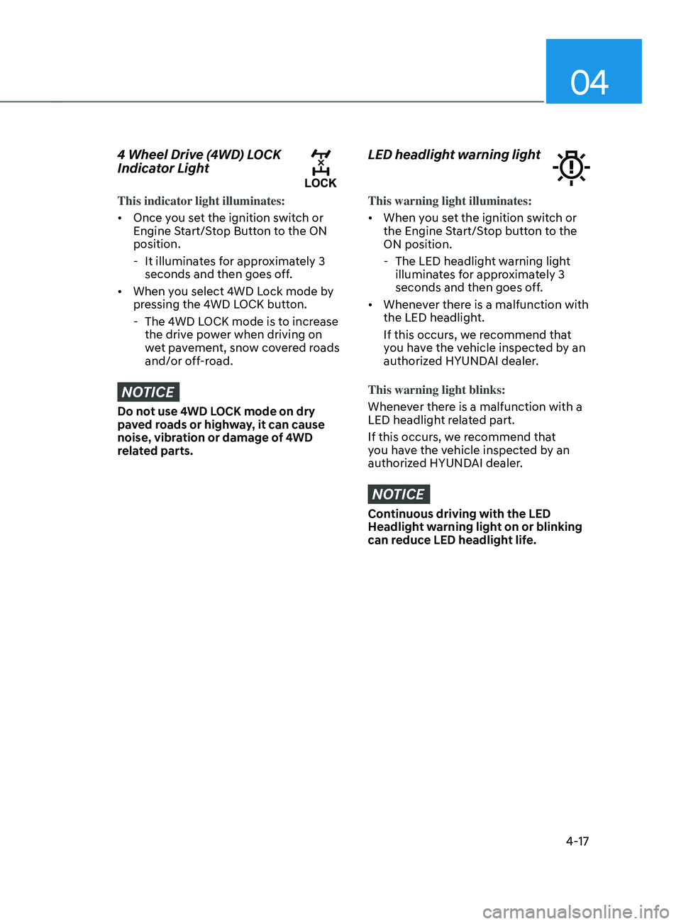
4 Wheel Drive (4WD) LOCK
Indicator Light
This indicator light illuminates:
• Once you set the ignition switch or
Engine Start/Stop Button to the ON
position.
- It illuminat
es for approximately 3
seconds and then goes off.
• When you select 4WD Lock mode by
pressing the 4WD LOCK button.
- The 4WD L
OCK mode is to increase
the drive power when driving on
wet pavement, snow covered roads
and/or off-road.
NOTICE
Do not use 4WD LOCK mode on dry
paved roads or highway, it can cause
noise, vibration or damage of 4WD
related parts.
LED headlight warning light
This warning light illuminates:
• When you set the ignition switch or
the Engine Start/Stop button to the
ON position.
- The LED headlight w
arning light
illuminates for approximately 3
seconds and then goes off.
• Whenever there is a malfunction with
the LED headlight.
If this occurs, we recommend that
you have the vehicle inspected by an
authorized HYUNDAI dealer.
This warning light blinks:
Whenever there is a malfunction with a
LED headlight related part.
If this occurs, we recommend that
you have the vehicle inspected by an
authorized HYUNDAI dealer.
NOTICE
Continuous driving with the LED
Headlight warning light on or blinking
can reduce LED headlight life.
Page 118 of 636
Instrument cluster
4-20
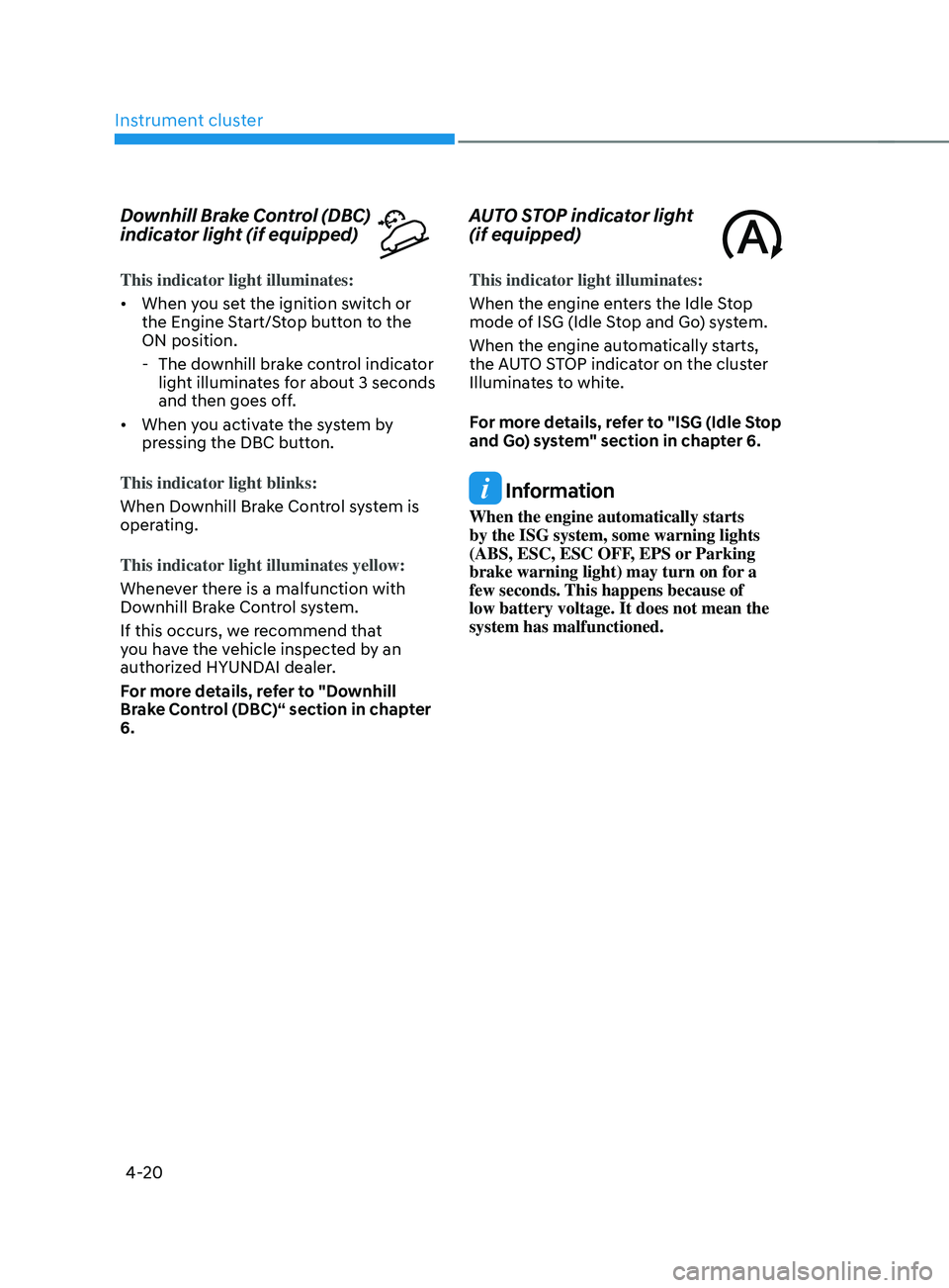
Downhill Brake Control (DBC)
indicator light (if equipped)
This indicator light illuminates:
• When you set the ignition switch or
the Engine Start/Stop button to the
ON position.
- The downhill br
ake control indicator
light illuminates for about 3 seconds
and then goes off.
• When you activate the system by
pressing the DBC button.
This indicator light blinks:
When Downhill Brake Control system is
operating.
This indicator light illuminates yellow:
Whenever there is a malfunction with
Downhill Brake Control system.
If this occurs, we recommend that
you have the vehicle inspected by an
authorized HYUNDAI dealer.
For more details, refer to "Downhill
Brake Control (DBC)“ section in chapter
6.
AUTO STOP indicator light
(if equipped)
This indicator light illuminates:
When the engine enters the Idle Stop
mode of ISG (Idle Stop and Go) system.
When the engine automatically starts,
the AUTO STOP indicator on the cluster
Illuminates to white.
For more details, refer to "ISG (Idle Stop
and Go) system" section in chapter 6.
Information
When the engine automatically starts
by the ISG system, some warning lights
(ABS, ESC, ESC OFF, EPS or Parking
brake warning light) may turn on for a
few seconds. This happens because of
low battery voltage. It does not mean the
system has malfunctioned.
Page 127 of 636
04
4-29
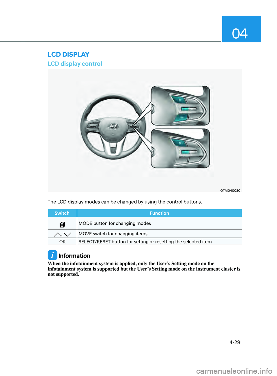
LCD display control
OTM040050
The LCD display modes can be changed by using the control buttons.
SwitchFunction
MODE button for changing modes
, MOVE switch for changing items
OK SELECT/RESET button for setting or resetting the selected item
Information
When the infotainment system is applied, only the User’s Setting mode on the
infotainment system is supported but the User’s Setting mode on the instrument cluster is
not supported.
LCD DISPLAY
Page 131 of 636
04
4-33
OTM080005L
Tire Pressure
This mode displays information related to
Tire Pressure.
For more details, refer to "Tire Pressure
Monitoring System (TPMS)" in chapter
8.
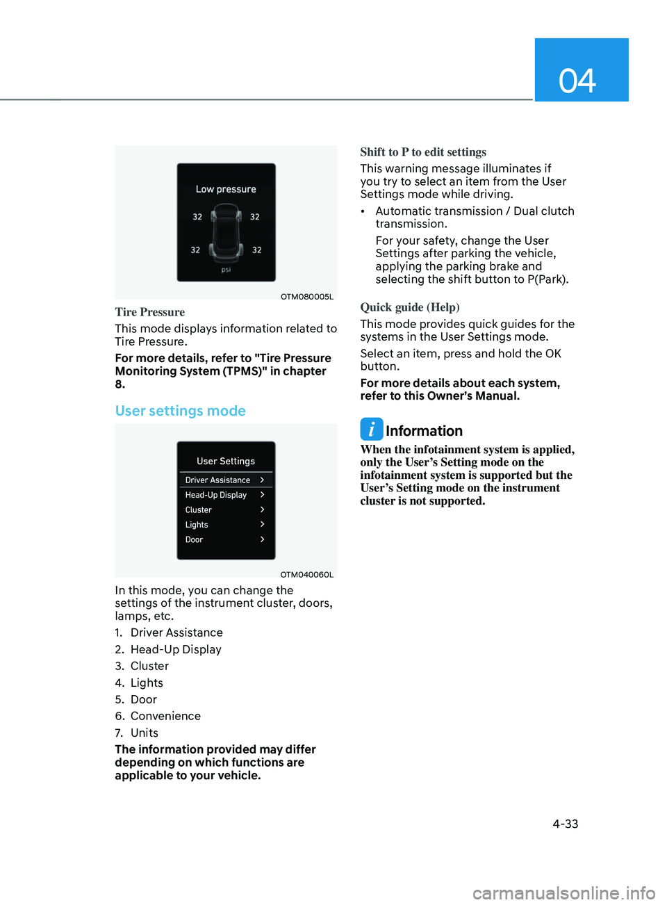
User settings mode
OTM040060L
In this mode, you can change the
settings of the instrument cluster, doors,
lamps, etc.
1.
Driver Assis
tance
2.
Head-Up Displa
y
3.
Clust
er
4.
Lights
5.
Door
6.
Conv
enience
7.
Units
The inf
ormation provided may differ
depending on which functions are
applicable to your vehicle. Shift to P to edit settings
This warning message illuminates if
you try to select an item from the User
Settings mode while driving.
•
Automatic transmission / Dual clutch
transmission.
For your safety, change the User
Settings after parking the vehicle,
applying the parking brake and
selecting the shift button to P(Park).
Quick guide (Help)
This mode provides quick guides for the
systems in the User Settings mode.
Select an item, press and hold the OK
button.
For more details about each system,
refer to this Owner’s Manual.
Information
When the infotainment system is applied,
only the User’s Setting mode on the
infotainment system is supported but the
User’s Setting mode on the instrument
cluster is not supported.