display HYUNDAI SANTA FE CALLIGRAPHY 2021 Owners Manual
[x] Cancel search | Manufacturer: HYUNDAI, Model Year: 2021, Model line: SANTA FE CALLIGRAPHY, Model: HYUNDAI SANTA FE CALLIGRAPHY 2021Pages: 636, PDF Size: 81.2 MB
Page 28 of 636

Vehicle Information, Consumer Information and Reporting Safety Defects
2-14
Recommended SAE viscosity number
CAUTION
Always be sure to clean the area around any filler plug, drain plug, or dipstick before
checking or draining any lubricant. This is especially important in dusty or sandy
areas and when the vehicle is used on unpaved roads. Cleaning the plug and dipstick
areas will prevent dirt and grit from entering the engine and other mechanisms that
could be damaged.
Engine oil viscosity (thickness) has an effect on fuel economy and cold weather
operating (engine start and engine oil flowability). Lower viscosity engine oils can
provide better fuel economy and cold weather performance, however, higher viscosity
engine oils are required for satisfactory lubrication in hot weather. Using oils of any
viscosity other than those recommended could result in engine damage.
When choosing an oil, consider the range of temperature your vehicle will be operated
in before the next oil change. Proceed to select the recommended oil viscosity from
the chart.
Temperature Range for SAE Viscosity Numbers
Temperature °C
-30-20-10 0 10 20 30 40 50
(°F) -100 20 40 60 80 100 120
Engine Oil *
1
Smartstream
G2.5 GDI0W-20 0W-20
Smartstream
G2.5 T-GDI0W-30
*1 : Requires
engine oil (mineral oil including Semi-synthetic) is used, then the engine oil and engine
oil filter must be replaced as indicated for severe maintenance condition.
An engine oil displaying this API Certification Mark conforms to
the international Lubricant Specification Advisory Committee
(ILSAC). It is recommended to only use engine oils that uphold
this API Certification Mark.
Page 54 of 636
Seats & Safety System
3-22
System precautions
• Make sure that all the windows are
closed. If the window is open, the
alert may operate by the sensor
detecting an unintended movement
(e.g. wind or bugs).
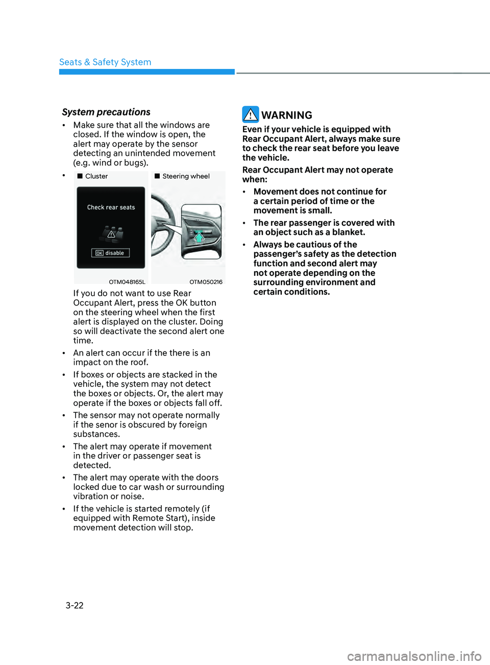
• „„Cluster „„Steering wheel
OTM048165LOTM050216
If you do not want to use Rear
Occupant Alert, press the OK button
on the steering wheel when the first
alert is displayed on the cluster. Doing
so will deactivate the second alert one
time.
• An alert can occur if the there is an
impact on the roof.
• If boxes or objects are stacked in the
vehicle, the system may not detect
the boxes or objects. Or, the alert may
operate if the boxes or objects fall off.
• The sensor may not operate normally
if the senor is obscured by foreign
substances.
• The alert may operate if movement
in the driver or passenger seat is
detected.
• The alert may operate with the doors
locked due to car wash or surrounding
vibration or noise.
• If the vehicle is started remotely (if
equipped with Remote Start), inside
movement detection will stop.
WARNING
Even if your vehicle is equipped with
Rear Occupant Alert, always make sure
to check the rear seat before you leave
the vehicle.
Rear Occupant Alert may not operate
when:
• Movement does not continue for
a certain period of time or the
movement is small.
• The rear passenger is covered with
an object such as a blanket.
• Always be cautious of the
passenger’s safety as the detection
function and second alert may
not operate depending on the
surrounding environment and
certain conditions.
Page 82 of 636

Seats & Safety System
3-50
How does the air bags system
operate?
OTMH030008N
The SRS consists of the following
components:
(1)
Driver's fr
ont air bag module
(2)
Passenger's fr
ont air bag module
(3)
Side air bag modules
(4)
Curtain air bag modules
(5)
Re
tractor pre-tensioner
(6)
Air bag warning ligh
t
(7)
SRS contr
ol module (SRSCM)/
Rollover sensor
(8)
Fr
ont impact sensors
(9)
Side impact sensors
(10) Side pressure sensors
(11) Seat belt buckle sensor
(12) Emergency fastening device system
(13) Occupant classification system
The SRSCM continually monitors all SRS
components while the ignition switch
is ON to determine if a crash impact
is severe enough to require air bag
deployment or pre-tensioner seat belt
deployment.
SRS warning light
The SRS (Supplemental Restraint System)
air bag warning light on the instrument
panel displays the air bag symbol
depicted in the illustration. The system
checks the air bag electrical system for
malfunctions. The light indicates that
there is a potential problem with your
air bag system, which could include
your side and/or curtain air bags used
for rollover protection (if equipped with
rollover sensor).
WARNING
If your SRS malfunctions, the air bag
may not inflate properly during an
accident increasing the risk of serious
injury or death.
If any of the following conditions occur,
your SRS is malfunctioning:
• The light does not turn on for
approximately three to six seconds
when the Engine Start/Stop button is
in the ON position.
• The light stays on after illuminating
for approximately three to six
seconds.
• The light comes on while the vehicle
is in motion.
• The light blinks when the engine is
running.
We recommend that an authorized
HYUNDAI dealer inspect the SRS
as soon as possible if any of these
conditions occur.
Page 100 of 636
AUTO STOP indicator light ........................................................................\
..............4-20
T urn signal indicator light ........................................................................\
................. 4-
21
High beam indicator light
........................................................................\
................ 4-
21
High Beam Assist indicator light
........................................................................\
...... 4-
21
Cruise Indicator Light
........................................................................\
....................... 4-
21
SPORT Mode Indicator Light
........................................................................\
........... 4-
22
ECO Mode Indicator Light
........................................................................\
............... 4-
22
SMART Mode Indicator Light
........................................................................\
.......... 4-22
Mas
ter warning light
........................................................................\
........................ 4-
22
LCD display messages
........................................................................\
....................... 4-
23
Shift to P (for smart key system)
........................................................................\
..... 4-
23
Low key battery (for smart key system).................................................................. 4-23
Press START button while turning wheel (for smart key system)
......................... 4-
23
Check steering wheel lock system
(for smart key system)
........................................................................\
..................... 4-
23
Press brake pedal to start engine (for smart key system)
.................................... 4-
23
Key not in vehicle (for smart key system)
............................................................... 4-23
K
ey not detected (for smart key system)................................................................ 4-23
Press START button again (for smart key system)
................................................ 4-
23
Press START button with key (for smart key system)
........................................... 4
-24
Check BRAKE SWITCH fuse (for smart key system)
............................................. 4
-24
Shift to P or N to start engine (for smart key system)
.......................................... 4
-24
Battery discharging due to external electrical devices
......................................... 4
-24
Door, Hood, Liftgate open indicator
....................................................................... 4-25
Sunr
oof open indicator
........................................................................\
.................... 4-
25
Low tire pressure
........................................................................\
............................. 4-
25
Lights
........................................................................\
................................................ 4-
26
Wiper
........................................................................\
.....................................
...........4-26
Low washer fluid
........................................................................\
.............................. 4-
26
Low fuel
........................................................................\
.....................................
.......4-26
Low engine oil
........................................................................\
.................................. 4-
26
Engine overheated / Engine has overheated
......................................................... 4-
27
Check exhaust system
........................................................................\
..................... 4-
27
Check headlight
........................................................................\
............................... 4-
27
Check turn signal
........................................................................\
............................. 4-
27
Check headlamp LED
........................................................................\
...................... 4-
27
Check Forward Collision-Avoidance Assist system
............................................... 4-
28
Check Lane Keeping Assist system
........................................................................\
4-28
Check Blind-
Spot Collision Warning system..........................................................4-28
Check Driver Attention Warning system
................................................................ 4-
28
Check High Beam Assist system
........................................................................\
..... 4-
28
Check Smart Cruise Control system
....................................................................... 4-28
4
Page 101 of 636
4. Instrument cluster
LCD display ........................................................................\
..............................4-29LCD display control ........................................................................\
............................4-29
Vie w modes ........................................................................\
....................................... 4-
30
Trip computer mode
........................................................................\
........................ 4-
31
Turn By Turn (TBT) mode
........................................................................\
................. 4-
31
Driving Assist mode
........................................................................\
......................... 4-
31
Master warning group
........................................................................\
..................... 4-
32
User settings mode
........................................................................\
............................ 4-
33
Trip computer (Type A)........................................................................\
...................... 4-40 Trip modes
........................................................................\
....................................... 4-40
T
rip computer (Type B)........................................................................\
...................... 4-43Trip modes
........................................................................\
....................................... 4-43
4
Page 103 of 636
04
4-5
Instrument cluster control
Instrument panel illumination
When the vehicle’s parking lights or
headlamps are on, press the illumination
control switch to adjust the brightness of
the instrument panel illumination.
When pressing the illumination control
switch, the interior switch illumination
intensity also adjusted.
You can adjust the brightness of the
instrument panel illumination form the
User Settings Mode on the LCD display
when
the ignition s
witch
is on (‘Ligh
ts
→ Illumination
’). When the vehicle’s parking
lights or headlamps are on, interior
switch illumination intensity and mood
lamps are also adjusted.
If your vehicle is equipped with
additional navigation, please refer
to the infotainment system manual
separately supplied.
WARNING
Never adjust the instrument cluster
while driving. This could result in loss
of control and lead to an accident that
may cause death, serious injury, or
vehicle damage.
• The brightness of the instrument
panel illumination is displayed.
• If the brightness reaches to the
maximum or minimum level, a chime
will sound.
Gauges and meters
Speedometer
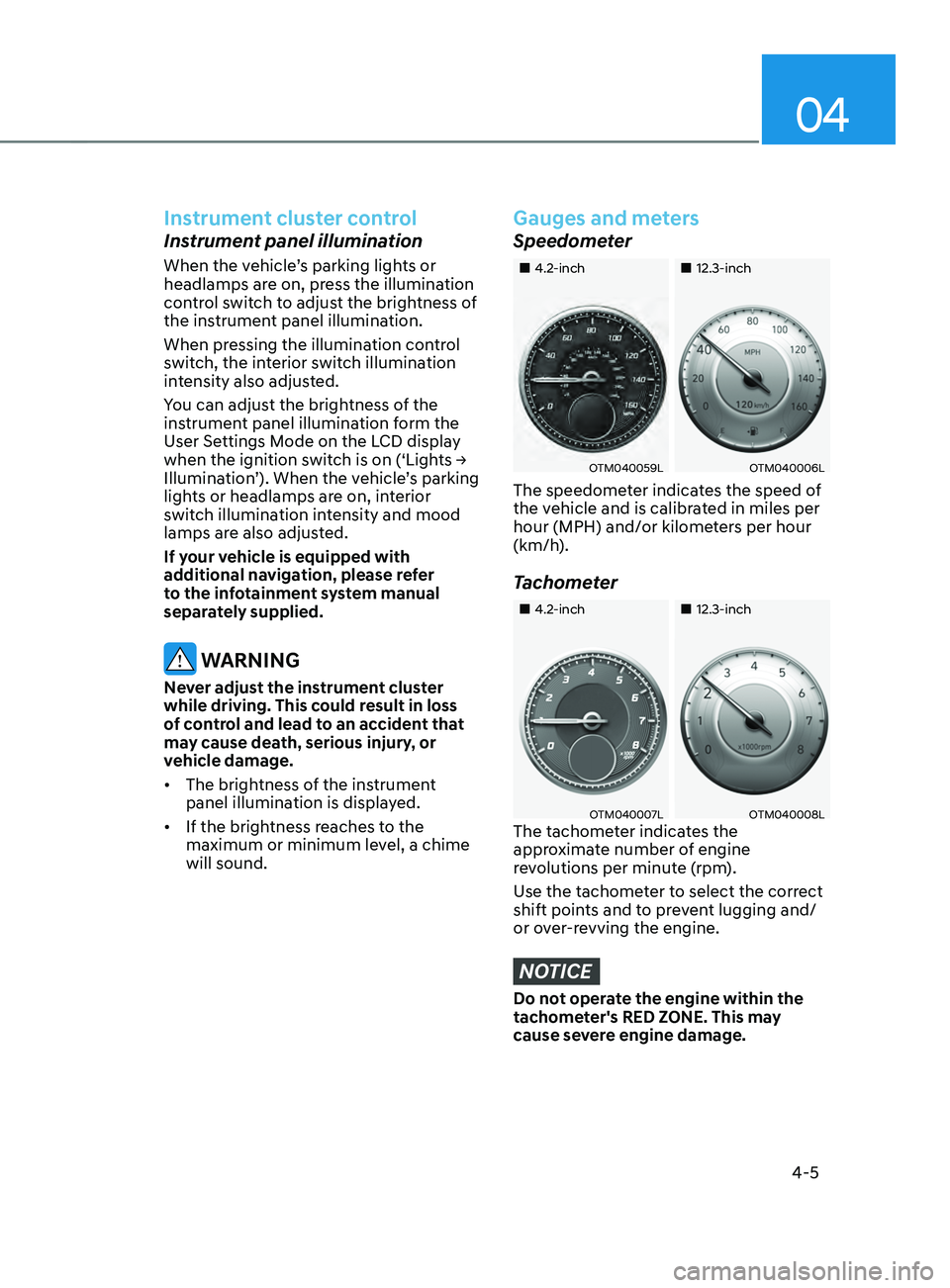
„„4.2-inch „„12.3-inch
OTM040059LOTM040006L
The speedometer indicates the speed of
the vehicle and is calibrated in miles per
hour (MPH) and/or kilometers per hour
(km/h).
Tachometer
„„4.2-inch„„12.3-inch
OTM040007LOTM040008LThe tachometer indicates the
approximate number of engine
revolutions per minute (rpm).
Use the tachometer to select the correct
shift points and to prevent lugging and/
or over-revving the engine.
NOTICE
Do not operate the engine within the
tachometer's RED ZONE. This may
cause severe engine damage.
Page 105 of 636
04
4 -7
Information
• The fuel tank capacity is given in
chapter 2.
• The fuel gauge is supplemented by
a low fuel warning light, which will
illuminate when the fuel tank is nearly
empty.
• On inclines or curves, the fuel gauge
pointer may fluctuate or the low fuel
warning light may come on earlier than
usual due to the movement of fuel in
the tank.
WARNING
Running out of fuel can expose vehicle
occupants to danger.
You must stop and obtain additional
fuel as soon as possible after the
warning light comes on or when the
gauge indicator comes close to the “E
(Empty) or 0” level.
NOTICE
Avoid driving with an extremely low
fuel level. Running out of fuel could
cause the engine to misfire damaging
the catalytic converter.
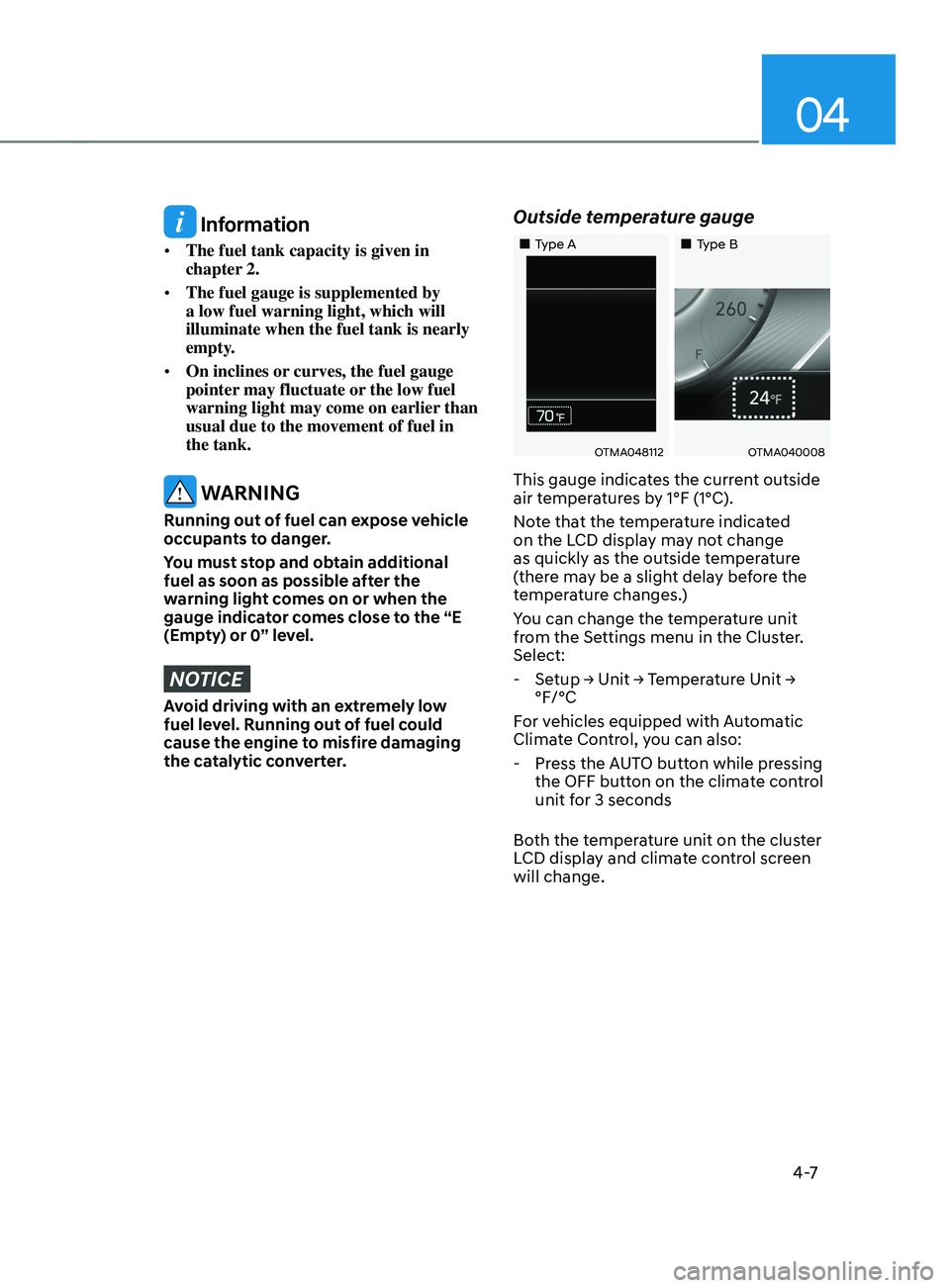
Outside temperature gauge
„„Type A „„Type B
OTMA048112OTMA040008
This gauge indicates the current outside
air temperatures by 1°F (1°C).
Note that the temperature indicated
on the LCD display may not change
as quickly as the outside temperature
(there may be a slight delay before the
temperature changes.)
You can change the temperature unit
from the Settings menu in the Cluster.
Select:
-Setup → Unit → T
emperature
Unit → °F/°C
For v
ehicles equipped with Automatic
Climate Control, you can also:
- Press the A
UTO button while pressing
the OFF button on the climate control
unit for 3 seconds
Both the temperature unit on the cluster
LCD display and climate control screen
will change.
Page 106 of 636

Instrument cluster
4-8
Odometer
„„4.2-inch„„12.3-inch
OTMA048183OCN7040015N
The odometer indicates the total
distance that the vehicle has been
driven and should be used to determine
when periodic maintenance should be
performed.
Distance to empty
„„4.2-inch„„12.3-inch
OAD048563LOCN7040016N
• The distance to empty is the
estimated distance the vehicle can be
driven with the remaining fuel.
• If the estimated distance is below
1 mi. (1 km), the trip computer will
display “---” as distance to empty.
Information
• If the vehicle is not on level ground or
the battery power has been interrupted,
the distance to empty function may not
operate correctly.
• The distance to empty may differ
from the actual driving distance as it
is an estimate of the available driving
distance.
• The trip computer may not register
additional fuel if less than 6 liters (1.5
gallon) of fuel are added to the vehicle.
• The distance to empty may vary
significantly based on driving
conditions, driving habits, and
condition of the vehicle.
Page 107 of 636

04
4-9
Fuel economy (for 12.3-inch cluster)
OTMA040002
The average fuel economy (1) and instant
fuel economy (2) is displayed at the
bottom of the cluster.
Automatic reset
To automatically reset the average fuel
economy, select between "After Ignition"
or "After Refueling" from the Settings
menu in the infotainment system screen.
Transmission shift indicator
Automatic transmission / Dual
clutch transmission shift indicator
„„4.2-inch„„12.3-inch
OTM040016OCN7040013N
This indicator informs the current gear
engaged.
Page 112 of 636

Instrument cluster
4-14
Exhaust system (GPF)
warning light (for gasoline
engine, if equipped)
• This warning light illuminates, when
accumulated soot reaches a certain
amount.
• When this warning light illuminates, it
may turn off after driving the vehicle
at more than 50 mph (80km/h) for
about 30 minutes (above 3rd gear
with 1500 ~ 4000 engine rpm).
If this warning light blinks in spite
of the procedure (at this time LCD
warning message will be displayed),
we recommend that you have the
GPF system checked by an authorized
HYUNDAI dealer.
NOTICE
If you continue to drive with the GPF
warning light blinking for a long time,
the GPF system can be damaged and
fuel consumption can worsen.
Electronic Parking Brake
(EPB) warning light
(if equipped)
This warning light illuminates:
• When you set the ignition switch or
the Engine Start/Stop button to the
ON position.
- The EPB warning ligh
t illuminates
for about 3 seconds and then goes
off.
• Whenever there is a malfunction with
EPB.
If this occurs, we recommend that
you have the vehicle inspected by an
authorized HYUNDAI dealer.
Information
The Electronic Parking Brake (EPB)
warning light may illuminate when
the Electronic Stability Control (ESC)
indicator light comes on to indicate that
ESC is not working properly. This does
not indicate malfunction of EPB.