engine HYUNDAI SANTA FE HYBRID 2021 Owners Manual
[x] Cancel search | Manufacturer: HYUNDAI, Model Year: 2021, Model line: SANTA FE HYBRID, Model: HYUNDAI SANTA FE HYBRID 2021Pages: 598, PDF Size: 66.6 MB
Page 555 of 598

Maintenance
9-40
■ Blade type
■ Cartridge type
■ Multi type Normal
Blown
Normal Blown
Normal Blown
OTM078035
A vehicle’s electrical system is protected
from electrical overload damage by
fuses.
This vehicle has 2 (or 3) fuse panels, one
located in the driver’s side panel bolster,
the other in the engine compartment.
If any of your vehicle’s lights,
accessories, or controls do not work,
check the appropriate circuit fuse. If a
fuse has blown, the element inside the
fuse will be melted or broken.
If the electrical system does not work,
first check the driver’s side fuse panel.
Before replacing a blown fuse, turn the
engine and all switches off, and then
disconnect the negative battery cable.
Always replace a blown fuse with one of
the same rating.
If the replacement fuse blows, this
indicates an electrical problem.
Avoid using the system involved. We
recommend that you immediately
consult an authorized HYUNDAI dealer.
Information
Three kinds of fuses are used: blade type
for lower amperage rating, cartridge
type, and multi fuse for higher amperage
ratings.
FUSES
Page 556 of 598
09
9-41
WARNING
NEVER replace a fuse with anything but
another fuse of the same rating.
• A higher capacity fuse could cause
damage and possibly cause a fire.
• Do not install a wire or aluminum
foil instead of the proper fuse -
even as a temporary repair. It may
cause extensive wiring damage and
possibly a fire.
NOTICE
Do not use a screwdriver or any other
metal object to remove fuses because
it may cause a short circuit and damage
the system.
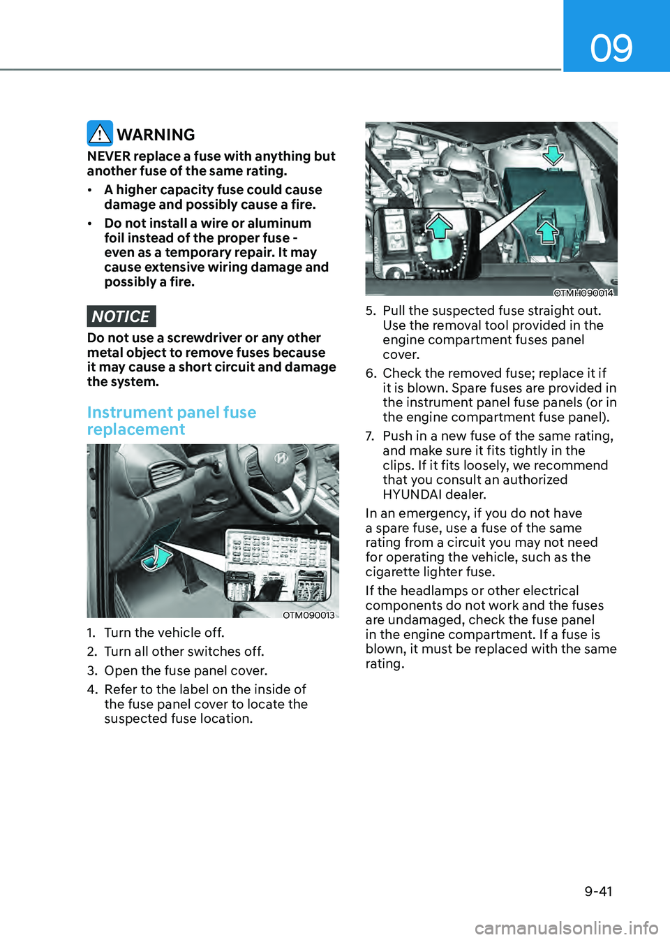
Instrument panel fuse
replacement
OTM090013
1. Turn the vehicle off.
2. Turn all other switches off.
3. Open the fuse panel cover.
4. Refer to the label on the inside of
the fuse panel cover to locate the
suspected fuse location.
OTMH090014
5. Pull the suspected fuse straight out.
Use the removal tool provided in the
engine compartment fuses panel
cover.
6. Check the removed fuse; replace it if
it is blown. Spare fuses are provided in
the instrument panel fuse panels (or in
the engine compartment fuse panel).
7. Push in a new fuse of the same rating,
and make sure it fits tightly in the
clips. If it fits loosely, we recommend
that you consult an authorized
HYUNDAI dealer.
In an emergency, if you do not have
a spare fuse, use a fuse of the same
rating from a circuit you may not need
for operating the vehicle, such as the
cigarette lighter fuse.
If the headlamps or other electrical
components do not work and the fuses
are undamaged, check the fuse panel
in the engine compartment. If a fuse is
blown, it must be replaced with the same
rating.
Page 557 of 598

Maintenance
9-42
Engine compartment panel fuse
replacement
„„Blade type fuse
OTMH090015
„„Cartridge type fuse
OTMH090016
1. Turn the vehicle off.
2. Turn all other switches off.
3. Remove the fuse panel cover by
pressing the tap and pulling up.
4. Check the removed fuse; replace it
if it is blown. To remove or insert the
fuse, use the fuse puller in the engine
compartment fuse panel.
5. Push in a new fuse of the same rating,
and make sure it fits tightly in the
clips. If it fits loosely, we recommend
that you consult an authorized
HYUNDAI dealer.
NOTICE
After checking the fuse panel in the
engine compartment, securely
install the fuse panel cover. You may
hear a clicking sound if the cover is
securely latched. If it is not securely
latched, electrical failure may occur
from water contact.
Multi fuse
OTMH090017
If the multi fuse is blown, we recommend
that you consult an authorized HYUNDAI
dealer.
Page 562 of 598
09
9-47
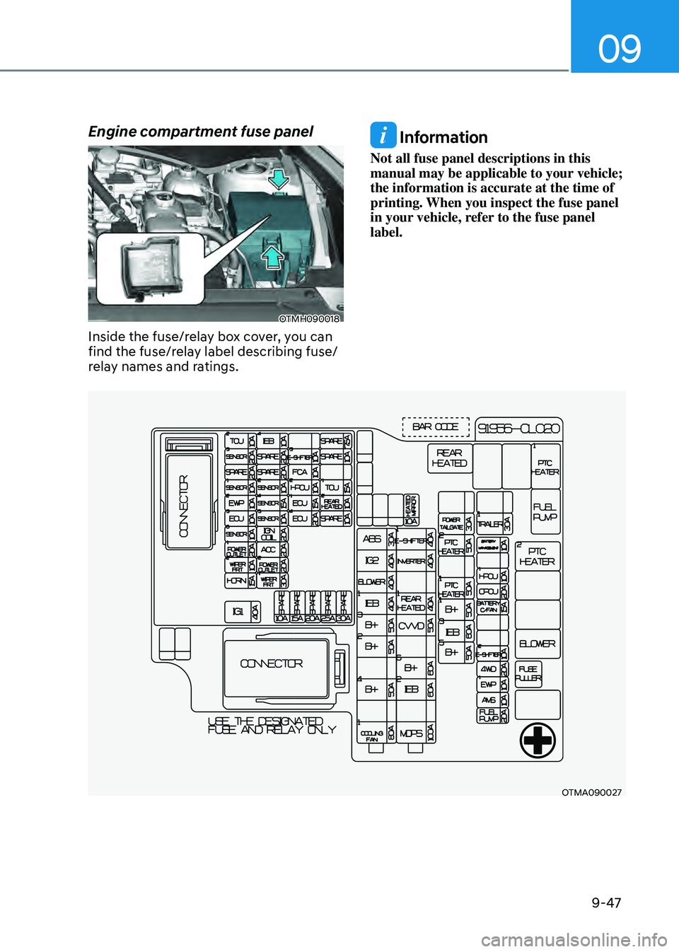
Engine compartment fuse panel
OTMH090018
Inside the fuse/relay box cover, you can
find the fuse/relay label describing fuse/
relay names and ratings.
Information
Not all fuse panel descriptions in this
manual may be applicable to your vehicle;
the information is accurate at the time of
printing. When you inspect the fuse panel
in your vehicle, refer to the fuse panel
label.
OTMA090027
Page 563 of 598
Maintenance
9-48
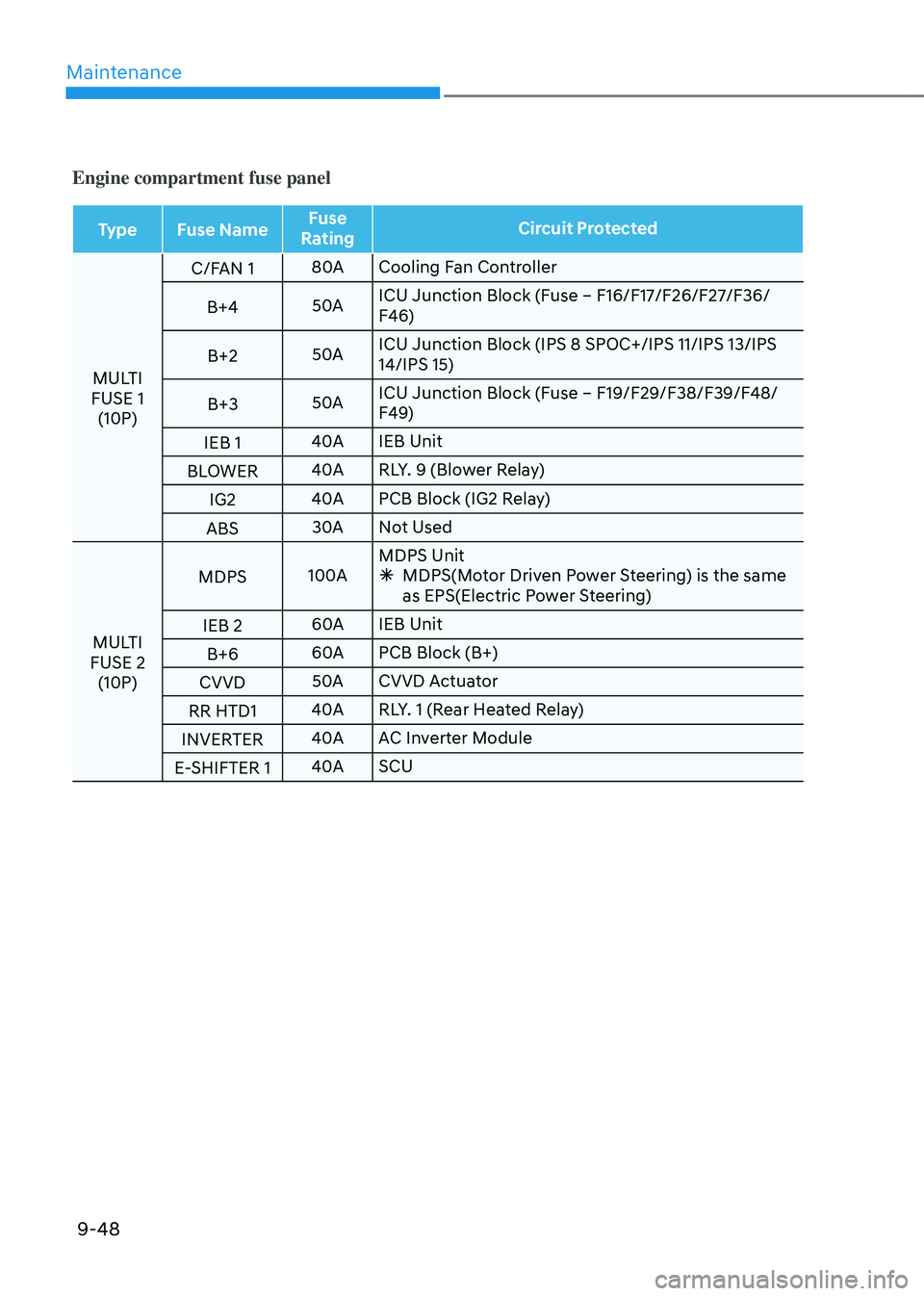
Engine compartment fuse panel
TypeFuse Name Fuse
Rating Circuit Protected
MULTI
FUSE 1 (10P) C/FAN 1
80A
Cooling Fan Controller
B+4 50AICU Junction Block (Fuse – F16/F17/F26/F27/F36/
F46)
B+2 50AICU Junction Block (IPS 8 SPOC+/IPS 11/IPS 13/IPS
14/IPS 15)
B+3 50AICU Junction Block (Fuse – F19/F29/F38/F39/F48/
F49)
IEB 1 40A
IEB Unit
BLOWER 40A
RLY. 9 (Blower Relay)
IG2 40A
PCB Block (IG2 Relay)
ABS 30A
Not Used
MULTI
FUSE 2 (10P) MDPS
100AMDPS Unit
Ã
MDPS(Motor Driven Power Steering) is the same
as EPS(Electric Power Steering)
IEB 2 60A
IEB Unit
B+6 60A
PCB Block (B+)
CVVD 50A
CVVD Actuator
RR HTD1 40A
RLY. 1 (Rear Heated Relay)
INVERTER 40A
AC Inverter Module
E-SHIFTER 1 40A
SCU
Page 564 of 598
09
9-49
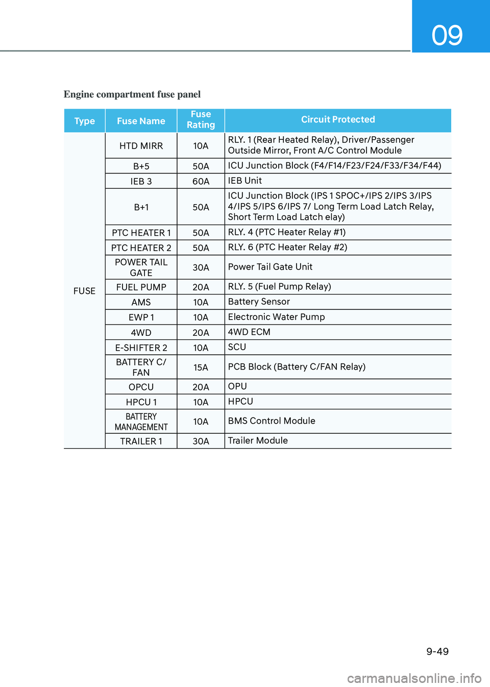
Engine compartment fuse panel
TypeFuse Name Fuse
Rating Circuit Protected
FUSE HTD MIRR
10ARLY. 1 (Rear Heated Relay), Driver/Passenger
Outside Mirror, Front A/C Control Module
B+5 50AICU Junction Block (F4/F14/F23/F24/F33/F34/F44)
IEB 3 60AIEB Unit
B+1 50AICU Junction Block (IPS 1 SPOC+/IPS 2/IPS 3/IPS
4/IPS 5/IPS 6/IPS 7/ Long Term Load Latch Relay,
Short Term Load Latch elay)
PTC HEATER 1 50ARLY. 4 (PTC Heater Relay #1)
PTC HEATER 2 50ARLY. 6 (PTC Heater Relay #2)
POWER TAIL GATE 30A
Power Tail Gate Unit
FUEL PUMP 20ARLY. 5 (Fuel Pump Relay)
AMS 10ABattery Sensor
EWP 1 10AElectronic Water Pump
4WD 20A4WD ECM
E-SHIFTER 2 10ASCU
BATTERY C/ FAN 15A
PCB Block (Battery C/FAN Relay)
OPCU 20AOPU
HPCU 1 10AHPCU
BATTERY
MANAGEMENT10A BMS Control Module
TRAILER 1 30ATrailer Module
Page 565 of 598
Maintenance
9-50
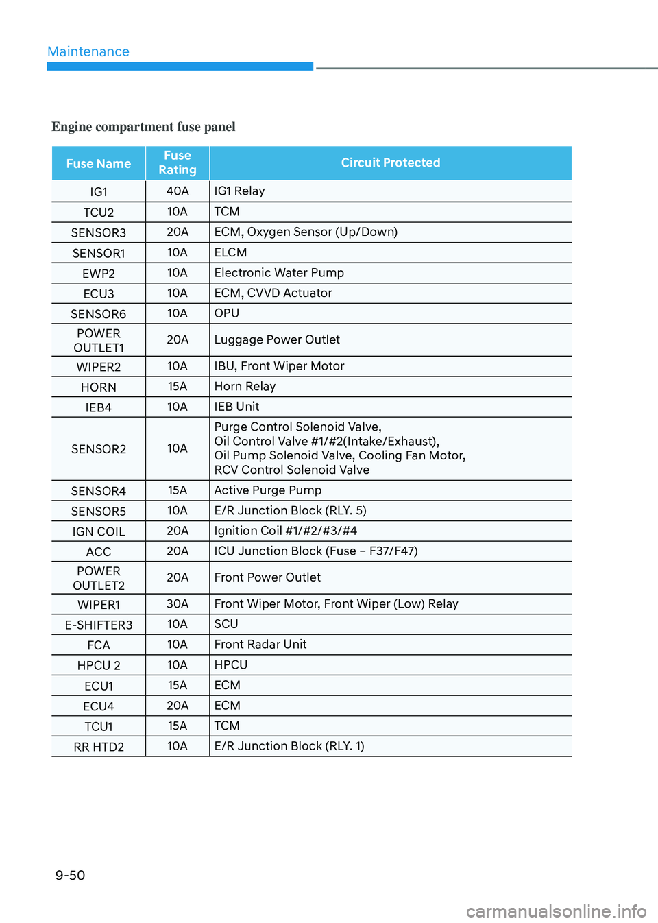
Engine compartment fuse panel
Fuse NameFuse
Rating Circuit Protected
IG1 40A
IG1 Relay
TCU2 10A
TCM
SENSOR3 20A
ECM, Oxygen Sensor (Up/Down)
SENSOR1 10A
ELCM
EWP2 10A
Electronic Water Pump
ECU3 10A
ECM, CVVD Actuator
SENSOR6 10A
OPU
POWER
OUTLET1 20A
Luggage Power Outlet
WIPER2 10A
IBU, Front Wiper Motor
HORN 15A
Horn Relay
IEB4 10A
IEB Unit
SENSOR2 10APurge Control Solenoid Valve,
Oil Control Valve #1/#2(Intake/Exhaust),
Oil Pump Solenoid Valve, Cooling Fan Motor,
RCV Control Solenoid Valve
SENSOR4 15A
Active Purge Pump
SENSOR5 10A
E/R Junction Block (RLY. 5)
IGN COIL 20A
Ignition Coil #1/#2/#3/#4
ACC 20A
ICU Junction Block (Fuse – F37/F47)
POWER
OUTLET2 20A
Front Power Outlet
WIPER1 30A
Front Wiper Motor, Front Wiper (Low) Relay
E-SHIFTER3 10A
SCU
FCA 10A
Front Radar Unit
HPCU 2 10A
HPCU
ECU1 15A
ECM
ECU4 20A
ECM
TCU1 15A
TCM
RR HTD2 10A
E/R Junction Block (RLY. 1)
Page 569 of 598

Maintenance
9-54
Rear combination lamp
replacement
Type A
OTMA090021
(1) Tail/Stop lamp
(2) Tail lamp
(3) Turn signal lamp
(4) Reverse lamp
(5) Side marker lamp
OTM090044
Stop/Tail lamp (Outside), Reverse lamp
1. Turn off the engine.
2. Open the liftgate.
3. Loosen the lamp assembly retaining
screws with a cross-tip screwdriver.
4. Remove the rear combination lamp
assembly from the body of the
vehicle.
5. Remove the socket from the
assembly by turning the socket
counterclockwise until the tabs on
the socket align with the slots on the
assembly.
OTM090045L
6. Remove the bulb from the socket
by pressing it in and rotating it
counterclockwise until the tabs on the
bulb align with the slots in the socket.
Pull the bulb out of the socket.
7. Insert a new bulb by inserting it into
the socket and rotating it until it locks
into place.
8. Install the socket into the assembly by
aligning the tabs on the socket with
the slots in the assembly. Push the
socket into the assembly and turn the
socket clockwise.
9. Reinstall the lamp assembly to the
body of the vehicle.
Page 570 of 598

09
9-55
OTM090025
Tail lamp (Inside)
1. Turn off the engine.
2. Open the liftgate.
3. Remove the service cover using a
flat-blade screwdriver.
4. Remove the socket from the
assembly by turning the socket
counterclockwise until the tabs on
the socket align with the slots on the
assembly.
OTM090046
5. Remove the bulb from the socket
by pressing it in and rotating it
counterclockwise until the tabs on the
bulb align with the slots in the socket.
Pull the bulb out of the socket.
6. Insert a new bulb by inserting it into
the socket and rotating it until it locks
into place.
7. Install the socket into the assembly by
aligning the tabs on the socket with
the slots in the assembly. Push the
socket into the assembly and turn the
socket clockwise.
8. Reinstall the lamp assembly to the
body of the vehicle.
Turn signal lamp
If these lamps do not operate, we
recommend that you have the vehicle
checked by an authorized HYUNDAI
dealer.
Page 571 of 598

Maintenance
9-56
Type B
OTMA090022
(1) Tail/Stop lamp
(2) Stop lamp
(3) Turn signal lamp
(4) Reverse lamp
(5) Side marker lamp
OTM090044
Reverse lamp
1. Turn off the engine.
2. Open the liftgate.
3. Loosen the lamp assembly retaining
screws with a cross-tip screwdriver.
4. Remove the rear combination lamp
assembly from the body of the
vehicle.
5. Remove the socket from the
assembly by turning the socket
counterclockwise until the tabs on
the socket align with the slots on the
assembly.
OTM090045L
6. Remove the bulb from the socket
by pressing it in and rotating it
counterclockwise until the tabs on the
bulb align with the slots in the socket.
Pull the bulb out of the socket.
7. Insert a new bulb by inserting it into
the socket and rotating it until it locks
into place.
8. Install the socket into the assembly by
aligning the tabs on the socket with
the slots in the assembly. Push the
socket into the assembly and turn the
socket clockwise.
9. Reinstall the lamp assembly to the
body of the vehicle.
Tail / Stop lamp, Tail lamp, Turn signal
lamp
If these lamps do not operate, we
recommend that you have the vehicle
checked by an authorized HYUNDAI
dealer.