ABS Hyundai Santa Fe Sport 2015 User Guide
[x] Cancel search | Manufacturer: HYUNDAI, Model Year: 2015, Model line: Santa Fe Sport, Model: Hyundai Santa Fe Sport 2015Pages: 785, PDF Size: 13.38 MB
Page 628 of 785

559
Driving your vehicle
Hazardous driving conditions
When hazardous driving conditions
are encountered such as water,
snow, ice, mud, sand, or similar haz-
ards, follow these suggestions:
• Drive cautiously and allow extra
distance for braking.
• Avoid sudden braking or steering.
• When braking with non-ABS
brakes pump the brake pedal with
a light up-and-down motion until
the vehicle is stopped.• If stalled in snow, mud, or sand, use
second gear. Accelerate slowly to
avoid spinning the drive wheels.
• Use sand, rock salt or other non-
slip material under the drive
wheels to provide traction when
stalled in ice, snow, or mud.
Reducing the risk of a rollover
This multi-purpose passenger vehicle
is defined as a Sports Utility Vehicle
(SUV). SUV’s have higher ground
clearance and a narrower track to
make them capable of performing in a
wide variety of off-road applications.
Specific design characteristics give
them a higher center of gravity than
ordinary vehicles. An advantage of the
higher ground clearance is a better
view of the road, which allows you to
anticipate problems. They are not
designed for cornering at the same
speeds as conventional passenger
vehicles, any more than low-slung
sports vehicles are designed to per-
form satisfactorily in off-road condi-
tions. Due to this risk, driver and pas-
sengers are strongly recommended to
buckle their seat belts. In a rollover
crash, an unbelted person is more like-
ly to die than a person wearing a seat
belt. There are steps that a driver can
make to reduce the risk of a rollover.
If at all possible, avoid sharp turns or
abrupt maneuvers, do not load your
roof rack with heavy cargo, and
never modify your vehicle in any way.
SPECIAL DRIVING CONDITIONS
WARNING - Downshifting
Downshifting with an automatic
transaxle, while driving on slip-
pery surfaces can cause an
accident. The sudden change in
tire speed could cause the tires
to skid. Be careful when down-
shifting on slippery surfaces.
WARNING - ABS
Do not pump the brake pedal on
a vehicle equipped with ABS.
Page 638 of 785

569
Driving your vehicle
Hitches
It's important to have the correct
hitch equipment. Crosswinds, large
trucks going by, and rough roads are
a few reasons why you’ll need the
right hitch. Here are some rules to
follow:
• Do you have to make any holes in
the body of your vehicle when you
install a trailer hitch? If you do, then
be sure to seal the holes later
when you remove the hitch.
If you don’t seal them, deadly car-
bon monoxide (CO) from your
exhaust can get into your vehicle,
as well as dirt and water.
• The bumpers on your vehicle are
not intended for hitches. Do not
attach rental hitches or other
bumper-type hitches to them. Use
only a frame-mounted hitch that
does not attach to the bumper.
• HYUNDAI trailer hitch accessory is
available at an authorized
HYUNDAI dealer.
Safety chains
You should always attach chains
between your vehicle and your trail-
er. Cross the safety chains under the
tongue of the trailer so that the
tongue will not drop to the road if it
becomes separated from the hitch.
Instructions about safety chains may
be provided by the hitch manufactur-
er or by the trailer manufacturer.
Follow the manufacturer’s recom-
mendation for attaching safety
chains. Always leave just enough
slack so you can turn with your trail-
er. And, never allow safety chains to
drag on the ground.
Trailer brakes
If your trailer is equipped with a brak-
ing system, make sure it conforms to
local regulations and that it is proper-
ly installed and operating correctly.
If your trailer weight exceeds the
maximum allowed weight without
trailer brakes, then the trailer will also
require its own brakes as well. Be
sure to read and follow the instruc-
tions for the trailer brakes so you’ll be
able to install, adjust and maintain
them properly.
• Don’t tap into or modify your vehi-
cle's brake system.
WARNING- Trailer brakes
Do not use a trailer with its own
brakes unless you are absolute-
ly certain that you have proper-
ly set up the brake system. This
is not a task for amateurs. Use
an experienced, competent
trailer shop for this work.
Page 641 of 785

Driving your vehicle
72 5
Parking on hills
Generally, if you have a trailer
attached to your vehicle, you should
not park your vehicle on a hill. People
can be seriously or fatally injured,
and both your vehicle and the trailer
can be damaged if they unexpected-
ly roll down hill.However, if you ever have to park your
trailer on a hill, here's how to do it:
1. Pull the vehicle into the parking
space. Turn the steering wheel in the
direction of the curb (right if headed
down hill, left if headed up hill).
2. If the vehicle has an automatic
transaxle, place the car in P (Park).
3. Set the parking brake and shut off
the vehicle.
4. Place chocks under the trailer
wheels on the down hill side of the
wheels.
5. Start the vehicle, hold the brakes,
shift to neutral, release the parking
brake and slowly release the
brakes until the trailer chocks
absorb the load.
6. Reapply the brakes, reapply the
parking brake and shift the vehicle
to P (Park) for automatic transaxle.
7. Shut off the vehicle and release
the vehicle brakes but leave the
parking brake set.
WARNING- Parking
on a hill
Parking your vehicle on a hill
with a trailer attached could
cause serious injury or death,
should the trailer break loose or
the brake stops working.
CAUTION
• When towing a trailer on steep
grades (in excess of 6%) pay
close attention to the engine
coolant temperature gauge to
ensure the engine does not
overheat.
If the needle of the coolant
temperature gauge moves
across the dial towards “H”
(HOT), pull over and stop as
soon as it is safe to do so, and
allow the engine to idle until it
cools down. You may proceed
once the engine has cooled
sufficiently.
• You must decide driving
speed depending on trailer
weight and uphill grade to
reduce the possibility of
engine and transaxle over-
heating.
Page 732 of 785
757
Maintenance
Tire replacement
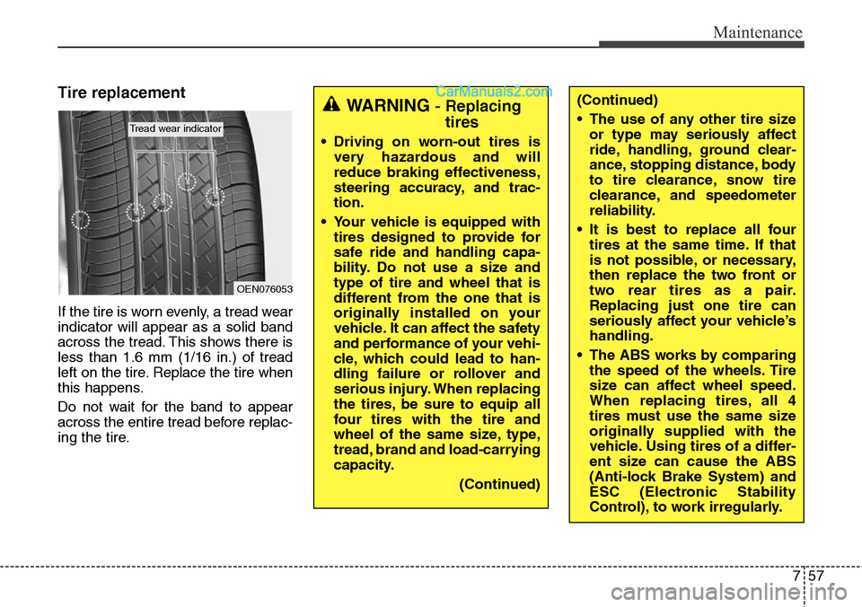
If the tire is worn evenly, a tread wear
indicator will appear as a solid band
across the tread. This shows there is
less than 1.6 mm (1/16 in.) of tread
left on the tire. Replace the tire when
this happens.
Do not wait for the band to appear
across the entire tread before replac-
ing the tire.
(Continued)
• The use of any other tire size
or type may seriously affect
ride, handling, ground clear-
ance, stopping distance, body
to tire clearance, snow tire
clearance, and speedometer
reliability.
• It is best to replace all four
tires at the same time. If that
is not possible, or necessary,
then replace the two front or
two rear tires as a pair.
Replacing just one tire can
seriously affect your vehicle’s
handling.
• The ABS works by comparing
the speed of the wheels. Tire
size can affect wheel speed.
When replacing tires, all 4
tires must use the same size
originally supplied with the
vehicle. Using tires of a differ-
ent size can cause the ABS
(Anti-lock Brake System) and
ESC (Electronic Stability
Control), to work irregularly.WARNING - Replacing
tires
• Driving on worn-out tires is
very hazardous and will
reduce braking effectiveness,
steering accuracy, and trac-
tion.
• Your vehicle is equipped with
tires designed to provide for
safe ride and handling capa-
bility. Do not use a size and
type of tire and wheel that is
different from the one that is
originally installed on your
vehicle. It can affect the safety
and performance of your vehi-
cle, which could lead to han-
dling failure or rollover and
serious injury. When replacing
the tires, be sure to equip all
four tires with the tire and
wheel of the same size, type,
tread, brand and load-carrying
capacity.
(Continued)
OEN076053
Tread wear indicator
Page 749 of 785

Maintenance
74 7
DescriptionFuse ratingProtected Component
START7.5AW/O IMMO. & Smart Key : ICM Relay Box (Burglar Alarm Relay)
With IMMO. or Smart Key : PCM, Transaxle Range Switch, Smart Key Control Module,
E/R Fuse & Relay Box (Start Relay)
MODULE 210ACrash Pad Switch, Multipurpose Check Connector, Head Lamp Leveling Device Actuator LH/RH,
Auto Head Lamp Leveling Device Module, Stop Lamp Switch
CORNERING LAMP10A-
SUNROOF 220ASunroof
S/HEATER RR15ARear Seat Warmer LH/RH
IGN20AE/R Fuse & Relay Box (Fuse - ABS 3, SENSOR 5, TCU)
A/CON 17.5AE/R Fuse & Relay Box (Blower Relay), A/C Control Module, Cluster Ionizer
WIPER RR15ARear Wiper Relay, Rear Wiper Motor, Multifunction Switch
SMART KEY 125ASmart Key Control Module
S/HEATER FRT20ADriver/Passenger CCS Control Module, Driver/Passenger Seat Warmer Module
A/CON 27.5AA/C Control Module
C/LIGHTER20AFront Power Outlet & Cigarette Lighter, Luggage Power Outlet
WIPER FRT15AMultifunction Switch, E/R Fuse & Relay Box (Wiper HI Relay, IG2 Relay)
BLOWER RR20A-
P/WDW RH 25APassenger Door Module, Rear Power Window Switch RH
RR HTD10AA/C Control Module
BRAKE SWITCH7.5ASmart Key Control Module, Stop Lamp Switch
Page 753 of 785

Maintenance
78 7
DescriptionFuse ratingProtected Component
MULTI
FUSE
MDPS80AMDPS Unit
B+260ASmart Junction Box (IPS 1 (4CH), IPS 2 (1CH), IPS 5 (1CH), Fuse - SUNROOF 1, P/SEAT
PASS, P/SEAT DRV)
BLOWER40ABlower Relay
RR HTD40ARear Defogger Relay
ABS140AESC Module, Multipurpose Check Connector
ABS240AESC Module
C/FAN60ACooling Fan Relay
B+360ASmart Junction Box (Fuse - MODULE 1, SMART KEY 4, SUNROOF 2, SMART KEY 1, Leak
Current Autocut Device)
FUSE
B+450ASmart Junction Box (IPS 3 (4CH), IPS 6 (2CH), Fuse - F/LID, STOP LAMP, DR LOCK, BRAKE
SWITCH)
EMS40AEMS Box
IG140AW/O Smart Key : Ignition Switch, With Smart Key - ACC Relay, IG1 Relay
IG240AStart Relay, IG2 Relay, W/O Smart Key : Ignition Switch
TRAILER30ATrailer Power Outlet
B+150ASmart Junction Box (Fuse - S/HEATER RR, S/HEATER FRT, P/WDW RH, P/WDW LH)
HORN15AHorn Relay
VACUUM PUMP20AVacuum Pump Relay
DEICER15AFront Deicer Relay
POWER OUTLET25APower Outlet Relay
Page 754 of 785

779
Maintenance
DescriptionFuse ratingProtected Component
FUSE
4WD20AAWD ECM
AMS10ABattery Sensor
AMS (WIPER)10ABCM, PCM
WIPER FRT25AWiper LO Relay, Front Wiper Motor
B/UP LAMP10AM/T - Back-Up Lamp Switch, A/T - Rear Combination Lamp (IN) LH/RH, Electro Chromic
Mirror, Audio, A/V & Navigation Head Unit
ABS37.5AESC Module
SENSOR57.5APCM
TCU15AA/T : Transaxle Range Switch, M/T : Fuse - B/UP LAMP (M/T)
F/PUMP15AFuel Pump Relay
ECU 115APCM
ECU 210A-
SENSOR 310AFuel Pump Relay, Camshaft Position Sensor #1/#2
IGN COIL20ACondenser, Ignition Coil #1/#2/#3/#4
SENSOR 210APurge Control Solenoid Valve, Variable Intake Solenoid Valve(G4KJ), RCV Control Solenoid
Valve(G4KH),Crankshaft Position Sensor, Oil Control Valve #1/#2, Canister Close Valve
SENSOR 115AOxygen Sensor (Up), Oxygen Sensor(Down), E/R Fuse & Relay Box (Cooling Fan Relay)
SENSOR 420APCM
B/A HORN10ABurglar Alarm Horn Relay
Page 757 of 785
Maintenance
82 7
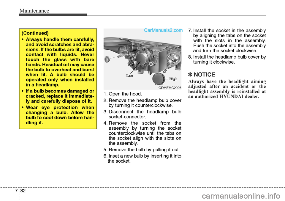
1. Open the hood.
2. Remove the headlamp bulb cover
by turning it counterclockwise.
3. Disconnect the headlamp bulb
socket-connector.
4. Remove the socket from the
assembly by turning the socket
counterclockwise until the tabs on
the socket align with the slots on
the assembly.
5. Remove the bulb by pulling it out.
6. Inset a new bulb by inserting it into
the socket.7. Install the socket in the assembly
by aligning the tabs on the socket
with the slots in the assembly.
Push the socket into the assembly
and turn the socket clockwise.
8. Install the headlamp bulb cover by
turning it clockwise.
✽NOTICE
Always have the headlight aiming
adjusted after an accident or the
headlight assembly is reinstalled at
an authorized HYUNDAI dealer.
(Continued)
• Always handle them carefully,
and avoid scratches and abra-
sions. If the bulbs are lit, avoid
contact with liquids. Never
touch the glass with bare
hands. Residual oil may cause
the bulb to overheat and burst
when lit. A bulb should be
operated only when installed
in a headlamp.
• If a bulb becomes damaged or
cracked, replace it immediate-
ly and carefully dispose of it.
• Wear eye protection when
changing a bulb. Allow the
bulb to cool down before han-
dling it.
ODMEMC2006
L L
o o
w wH H
i i
g g
h h
Page 758 of 785
783
Maintenance
Turn signal lamp/Position lamp
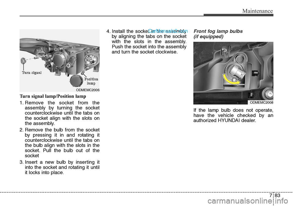
1. Remove the socket from the
assembly by turning the socket
counterclockwise until the tabs on
the socket align with the slots on
the assembly.
2. Remove the bulb from the socket
by pressing it in and rotating it
counterclockwise until the tabs on
the bulb align with the slots in the
socket. Pull the bulb out of the
socket
3. Insert a new bulb by inserting it
into the socket and rotating it until
it locks into place.4. Install the socket in the assembly
by aligning the tabs on the socket
with the slots in the assembly.
Push the socket into the assembly
and turn the socket clockwise.
Front fog lamp bulbs
(if equipped)
If the lamp bulb does not operate,
have the vehicle checked by an
authorized HYUNDAI dealer.
ODMEMC2006
T T
u u
r r
n n
s s
i i
g g
n n
a a
l l
P P
o o
s s
i i
t t
i i
o o
n n
l l
a a
m m
p p
ODMEMC2008
Page 760 of 785

785
Maintenance
Rear combination lamp bulb
replacement
(1) Rear stop and tail lamp
(2) Rear tail lamp
(3) Rear turn signal lamp
(4) Back-up lamp
(5) Rear side marker
Outside lamp
1. Open the tailgate.
2. Remove the service cover using a
flat-blade screwdriver.
3. Loosen the lamp assembly retain-
ing please verify.
4. Remove the rear combination
lamp assembly from the body of
the vehicle.
5. Remove the socket from the
assembly by turning the socket
counterclockwise until the tabs on
the socket align with the slots on
the assembly.
ODM072033
ODMEMC2007
■Type A
■Type BODM072034
ODM072035
ODMEMC2010 ■Type A
■Type B