Engine battery Hyundai Santa Fe Sport 2016 Owner's Manual
[x] Cancel search | Manufacturer: HYUNDAI, Model Year: 2016, Model line: Santa Fe Sport, Model: Hyundai Santa Fe Sport 2016Pages: 763, PDF Size: 37.75 MB
Page 7 of 763
1
2
3
4
5
6
7
8I
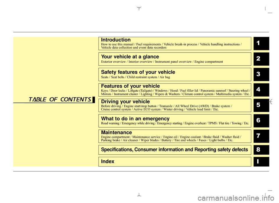
IntroductionHow to use this manual / Fuel requirements / Vehicle break-in process / Vehicle handling instructions /Vehicle data collection and event data recorders
Your vehicle at a glance
Exterior overview / Interior overview / Instrument panel overview / Engi\
ne compartment
Safety features of your vehicle
Seats / Seat belts / Child restraint system / Air bag
Features of your vehicleKeys / Door locks / Liftgate (Tailgate) / Windows / Hood / Fuel filler lid / Panoramic sunroof / Steering wheel /
Mirrors / Instrument cluster / Lighting / Wipers & Washers / Climate control system / Multimedia system / Etc.
Driving your vehicleBefore driving / Engine start/stop button / Transaxle / All Wheel Drive (AWD) / Brake system /
Cruise control system / Active ECO system / Winter driving / Vehicle load limit / Etc.
What to do in an emergencyRoad warning / Emergency while driving / Emergency starting / Engine overheat / TPMS / Flat tire / Towing / Etc.
MaintenanceEngine compartment / Maintenance service / Engine oil / Engine coolant /\
Brake fluid / Washer fluid /
Parking brake / Air cleaner / Wiper blades / Battery / Tire and wheels / Fuses / Light bulbs / Etc.
Specifications, Consumer information and Reporting safety defects
Index
table of contents
AN HMA FOREWORD.QXP 2015-05-07 ¿ ¨˜ 4:12 Page 7
Page 12 of 763
15
Introduction
VEHICLE BREAK-IN PROCESS
No special break-in period is needed.
By following a few simple precautions
for the first 600 miles (1,000 km) you
may add to the performance, econo-
my and life of your vehicle.
Do not race the engine.
While driving, keep your enginespeed (rpm, or revolutions per
minute) between 2,000 rpm and
4,000 rpm.
Do not maintain a single speed for long periods of time, either fast or
slow. Varying engine speed is
needed to properly break-in the
engine.
Avoid hard stops, except in emer- gencies, to allow the brakes to seat
properly. As with other vehicles of this type,
failure to operate this vehicle correct-
ly may result in loss of control, an
accident or vehicle rollover.
Specific design characteristics (high-
er ground clearance, track, etc.) give
this vehicle a higher center of gravity
than other types of vehicles. It is not
designed for cornering at the same
speeds as a conventional 2-wheel
drive sedans or sports coupe. Avoid
sharp turns or abrupt maneuvers.
Failure to operate this vehicle cor-
rectly may result in loss of control, an
accident or vehicle rollover.
Be sure
to read the “Reducing the risk of a
rollover” driving guidelines, in
section 5 of this manual.CALIFORNIA PROPO-
SITION 65 WARNING
Items contained in motor vehi-
cles or emitted from them are
known to the State of California
to cause cancer and birth
defects or reproductive harm.
These include:
ment components and materi-
als
subject to heat and wear
In addition, battery posts, termi-
nals and related accessories
contain lead, lead compounds
and other chemicals known to
the State of California to cause
cancer and reproductive harm.
VEHICLE HANDLING
INSTRUCTIONS
AN HMA 1.QXP 2015-02-03 ¿ 11:07 Page 5
Page 20 of 763
27
Your vehicle at a glance
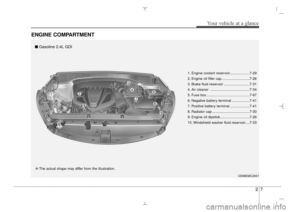
ENGINE COMPARTMENT
ODMEMC2001
❈The actual shape may differ from the illustration. 1. Engine coolant reservoir....................7-29
2. Engine oil filler cap ............................7-26
3. Brake fluid reservoir ..........................7-31
4. Air cleaner ........................................7-34
5. Fuse box ............................................7-67
6. Negative battery terminal ..................7-41
7. Positive battery terminal ....................7-41
8. Radiator cap ......................................7-30
9. Engine oil dipstick..............................7-26
10. Windshield washer fluid reservoir....7-33
■
Gasoline 2.4L GDI
AN HMA 2.QXP 6/10/2015 11:21 AM Page 7
Page 21 of 763
Your vehicle at a glance
82
ODMNMC2033
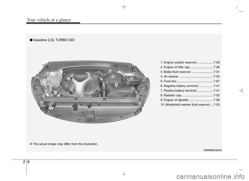
❈The actual shape may differ from the illustration. 1. Engine coolant reservoir....................7-29
2. Engine oil filler cap ............................7-26
3. Brake fluid reservoir ..........................7-31
4. Air cleaner ........................................7-34
5. Fuse box ............................................7-67
6. Negative battery terminal ..................7-41
7. Positive battery terminal ....................7-41
8. Radiator cap ......................................7-30
9. Engine oil dipstick..............................7-26
10. Windshield washer fluid reservoir....7-33
■
Gasoline 2.0L TURBO GDI
AN HMA 2.QXP 6/10/2015 11:21 AM Page 8
Page 27 of 763
Safety features of your vehicle
63
Lumbar support (for driver’s seat)
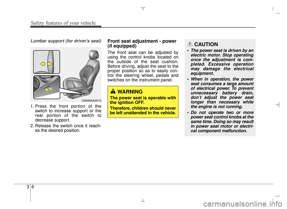
1. Press the front portion of theswitch to increase support or the
rear portion of the switch to
decrease support.
2. Release the switch once it reach- es the desired position.
Front seat adjustment - power
(if equipped)
The front seat can be adjusted by
using the control knobs located on
the outside of the seat cushion.
Before driving, adjust the seat to the
proper position so as to easily con-
trol the steering wheel, pedals and
switches on the instrument panel.
OANNSA2010
WARNING
The power seat is operable with
the ignition OFF.
Therefore, children should never
be left unattended in the vehicle.
CAUTION
The power seat is driven by anelectric motor. Stop operatingonce the adjustment is com-pleted. Excessive operationmay damage the electricalequipment.
When in operation, the power seat consumes a large amountof electrical power. To preventunnecessary battery drain,don’t adjust the power seatlonger than necessary whilethe engine is not running.
Do not operate two or more power seat control knobs at thesame time. Doing so may resultin power seat motor or electri-cal component malfunction.
AN HMA 3.QXP 3/5/2015 3:09 PM Page 6
Page 29 of 763
Safety features of your vehicle
83
Lumbar support (for driver’s seat, if equipped)
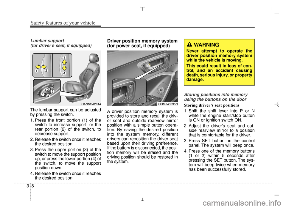
The lumbar support can be adjusted
by pressing the switch.
1. Press the front portion (1) of the switch to increase support, or the
rear portion (2) of the switch, to
decrease support.
2. Release the switch once it reaches the desired position.
3. Press the upper portion (3) of the switch to move the support position
up, or press the lower portion (4) of
the switch, to move the support
position down.
4. Release the switch once it reaches the desired position.
Driver position memory system
(for power seat, if equipped)
A driver position memory system is
provided to store and recall the driv-
er seat and outside rearview mirror
position with a simple button opera-
tion. By saving the desired position
into the system memory, different
drivers can reposition the driver seat
based upon their driving preference.
If the battery is disconnected, the posi-
tion memory will be erased and the
driving position should be restored in
the system.
Storing positions into memory
using the buttons on the door
Storing driver’s seat positions
1. Shift the shift lever into P or N while the engine start/stop button
is ON or ignition switch ON.
2. Adjust the driver’s seat and out- side rearview mirror to a position
that is comfortable for the driver.
3. Press SET button on the control panel. The system will beep once.
4. Press one of the memory buttons (1 or 2) within 5 seconds after
pressing the SET button. The sys-
tem will beep twice when memory
has been successfully stored.OANNSA2014ODM043335N
WARNING
Never attempt to operate the
driver position memory system
while the vehicle is moving.
This could result in loss of con-
trol, and an accident causing
death, serious injury, or property
damage.
AN HMA 3.QXP 3/5/2015 3:09 PM Page 8
Page 71 of 763
Safety features of your vehicle
50
3
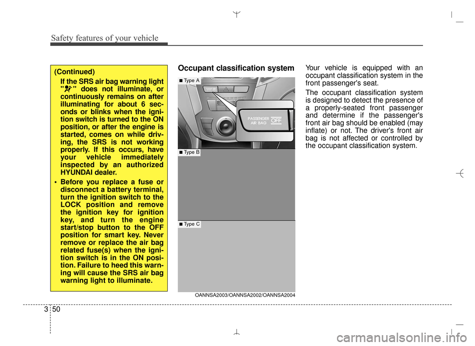
Occupant classification systemYour vehicle is equipped with an
occupant classification system in the
front passenger's seat.
The occupant classification system
is designed to detect the presence of
a properly-seated front passenger
and determine if the passenger's
front air bag should be enabled (may
inflate) or not. The driver's front air
bag is not affected or controlled by
the occupant classification system.(Continued)
If the SRS air bag warning light
" " does not illuminate, or
continuously remains on after
illuminating for about 6 sec-
onds or blinks when the igni-
tion switch is turned to the ON
position, or after the engine is
started, comes on while driv-
ing, the SRS is not working
properly. If this occurs, have
your vehicle immediately
inspected by an authorized
HYUNDAI dealer.
Before you replace a fuse or disconnect a battery terminal,
turn the ignition switch to the
LOCK position and remove
the ignition key for ignition
key, and turn the engine
start/stop button to the OFF
position for smart key. Never
remove or replace the air bag
related fuse(s) when the igni-
tion switch is in the ON posi-
tion. Failure to heed this warn-
ing will cause the SRS air bag
warning light to illuminate.
OANNSA2003/OANNSA2002/OANNSA2004
■ Type B
■Type A
■ Type C
AN HMA 3.QXP 3/5/2015 3:09 PM Page 50
Page 99 of 763
47
Features of your vehicle
Battery replacement
The transmitter uses a 3 volt lithium
battery which will normally last for
several years. When replacement is
necessary, use the following proce-
dure.
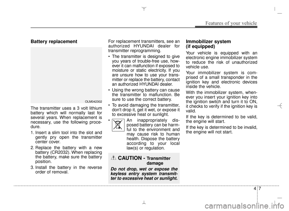
1. Insert a slim tool into the slot andgently pry open the transmitter
center cover.
2. Replace the battery with a new battery (CR2032). When replacing
the battery, make sure the battery
position.
3. Install the battery in the reverse order of removal. For replacement transmitters, see an
authorized HYUNDAI dealer for
transmitter reprogramming.
The transmitter is designed to give
you years of trouble-free use, how-
ever it can malfunction if exposed to
moisture or static electricity. If you
are unsure how to use your trans-
mitter or replace the battery, contact
an authorized HYUNDAI dealer.
Using the wrong battery can cause the transmitter to malfunction. Be
sure to use the correct battery.
To avoid damaging the transmitter, don't drop it, get it wet, or expose it
to excessive heat or sunlight.
An inappropriately dis- posed battery can be harm-
ful to the environment and
may cause risk to human
health. Dispose the battery
according to your local
law(s) or regulation.
Immobilizer system
(if equipped)
Your vehicle is equipped with an
electronic engine immobilizer system
to reduce the risk of unauthorized
vehicle use.
Your immobilizer system is com-
prised of a small transponder in the
ignition key and electronic devices
inside the vehicle.
With the immobilizer system, when-
ever you insert your ignition key into
the ignition switch and turn it to ON,
it checks to verify if the ignition key is
valid.
If the key is determined to be valid,
the engine will start.
If the key is determined to be invalid,
the engine will not start.
OLM042302
CAUTION - Transmitter
damage
Do not drop, wet or expose the keyless entry system transmit-ter to excessive heat or sunlight.
AN HMA 4A.QXP 3/5/2015 3:17 PM Page 7
Page 117 of 763
425
Features of your vehicle
Impact sensing door unlock
system
All doors will be automatically
unlocked if an impact or collision is
detected by the impact sensors while
the ignition switch is ON.
However, the doors may not be
unlocked if mechanical problems
occur with the door lock system or
battery.
✽ ✽NOTICE
You can select some auto door
lock/unlock features in “User
Settings” as follows;
• Speed sensing auto door lock
• Auto door unlock when the igni-
tion key is removed from the igni-
tion switch or engine is turned off.
• Auto door lock/unlock by shifting the shift lever out of P(Park) or
into P(Park).
For more information, refer to
“User Settings” in this section.
Child-protector rear door lock
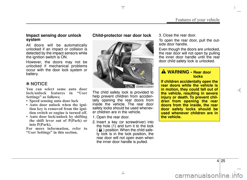
The child safety lock is provided to
help prevent children from acciden-
tally opening the rear doors from
inside the vehicle. The rear door
safety locks should be used whenev-
er children are in the vehicle.
1. Open the rear door.
2. Insert a key (or screwdriver) into
the hole (1) and turn it to the lock
( ) position. When the child safe-
ty lock is in the lock position, the
rear door will not open even when
the inner door handle is pulled. 3. Close the rear door.
To open the rear door, pull the out-
side door handle.
Even though the doors are unlocked,
the rear door will not open by pulling
the inner door handle until the rear
door child safety lock is unlocked.
WARNING - Rear door
locks
If children accidentally open the
rear doors while the vehicle is
in motion, they could fall out of
the vehicle, resulting in severe
injury or death. To prevent chil-
dren from opening the rear
doors from the inside, the rear
door safety locks should be
used whenever children are in
the vehicle.
ODMECO2031
AN HMA 4A.QXP 3/5/2015 3:18 PM Page 25
Page 123 of 763
431
Features of your vehicle
✽
✽NOTICE
• The power liftgate (power tailgate)
can be operated when the engine is
not running. However the power
liftgate (power tailgate) operation
consumes large amounts of vehicle
electric power. To prevent the bat-
tery from being discharged, do not
operate it excessively e.g.: more
than approximately 10 times
repeatedly.
• To prevent the battery from being discharged, do not leave the power
liftgate (power tailgate) in the
open position for a long lime.
• Do not modify or repair any part of the power liftgate (power tail-
gate) by yourself. This must be
done by an authorized HYUNDAI
dealer.
• When jacking up the vehicle to change a tire or repair the vehicle,
do not operate the power liftgate
(power tailgate). This could cause
the power liftgate (power tailgate)
to operate improperly.
• In cold and wet climates, the power liftgate (power tailgate) may
not work properly due to freezing
conditions.
Automatic reversal
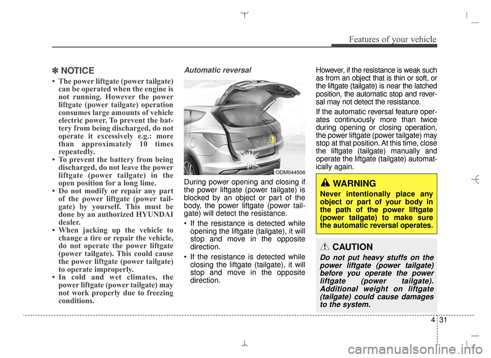
During power opening and closing if
the power liftgate (power tailgate) is
blocked by an object or part of the
body, the power liftgate (power tail-
gate) will detect the resistance.
If the resistance is detected while
opening the liftgate (tailgate), it will
stop and move in the opposite
direction.
If the resistance is detected while closing the liftgate (tailgate), it will
stop and move in the opposite
direction. However, if the resistance is weak such
as from an object that is thin or soft, or
the liftgate (tailgate) is near the latched
position, the automatic stop and rever-
sal may not detect the resistance.
If the automatic reversal feature oper-
ates continuously more than twice
during opening or closing operation,
the power liftgate (power tailgate) may
stop at that position. At this time, close
the liftgate (tailgate) manually and
operate the liftgate (tailgate) automat-
ically again.
ODM044506
WARNING
Never intentionally place any
object or part of your body in
the path of the power liftgate
(power tailgate) to make sure
the automatic reversal operates.
CAUTION
Do not put heavy stuffs on the
power liftgate (power tailgate)before you operate the powerliftgate (power tailgate).Additional weight on liftgate(tailgate) could cause damagesto the system.
AN HMA 4A.QXP 3/5/2015 3:18 PM Page 31