oil Hyundai Santa Fe Sport 2017 Owner's Guide
[x] Cancel search | Manufacturer: HYUNDAI, Model Year: 2017, Model line: Santa Fe Sport, Model: Hyundai Santa Fe Sport 2017Pages: 614, PDF Size: 18.99 MB
Page 518 of 614

721
Maintenance
MAINTENANCE UNDER SEVERE USAGE CONDITIONS
The following items must be serviced more frequently on cars normally used under severe driving conditions. Refer
to the chart below for the appropriate maintenance intervals.
R : Replace I : Inspect and, after inspection, clean, adjust, repair or replace if neces\
sary
MAINTENANCE ITEMMAINTENANCEOPERATIONMAINTENANCE INTERVALSDRIVING CONDI- TION
ENGINE OIL AND FILTER (2.4 GDI)REVERY 3,750 MILES (6,000 KM) OR 6 MONTHS
A, B, C, D, E, F, G,H, I, K, J
ENGINE OIL AND FILTER (2.0 TGDI)REVERY 3,000 MILES (5,000 KM) OR 3 MONTHS
AIR CLEANER FILTERRMORE FREQUENTLYC, E
SPARK PLUGSRMORE FREQUENTLYA, B, G, H, I, K
AUTOMATIC TRANSAXLE FLUIDREVERY 60,000 MILES (96,000 KM) A, C, E, F, G, I
FRONT BRAKE DISC/PADS, CALIPERSIMORE FREQUENTLYC, D, G, H
REAR BRAKE DISC /PADSIMORE FREQUENTLYC, D, G, H
PARKING BRAKEIMORE FREQUENTLYC, D, G, H
STEERING GEAR BOX, LINKAGE &
BOOTS/LOWER ARM BALL JOINT,
UPPER ARM BALL JOINT
IMORE FREQUENTLYC, D, E, F, G, H, I
Page 519 of 614

Maintenance
22
7
SEVERE DRIVING CONDITIONS
A - Repeatedly driving short distance of less than 5 miles (8 km)
in normal temperature or less than 10 miles (16 km) in freez-
ing temperature
B - Extensive engine idling or low speed driving for long dis- tances
C - Driving on rough, dusty, muddy, unpaved, graveled or salt- spread roads
D - Driving in areas using salt or other corrosive materials or in very cold weather
E - Driving in sandy areas F - Driving in heavy traffic area over 90°F (32°C)
G- Driving on uphill, downhill, or mountain road
H - Towing a Trailer, or using a camper, or roof rack
I - Driving as a patrol car, taxi, other commercial use or vehicle
towing
J - Driving over 106 mph (170 km/h)
K - Frequently driving in stop-and-go conditions
MAINTENANCE ITEMMAINTENANCE OPERATIONMAINTENANCE INTERVALSDRIVING CONDI- TION
DRIVE SHAFTS AND BOOTSIEVERY 7,500 MILES (12,000 KM) OR 6 MONTHSC, D, E, F, G, H, I, J
TRANSFER CASE OIL (AWD) REVERY 75,000 MILES (120,000 KM)C, D, E, G, H, I, J
REAR AXLE OIL (AWD)REVERY 75,000 MILES (120,000 KM)C, D, E, G, H, I, J
CLIMATE CONTROL AIR FILTER(FOR EVAPORATOR AND BLOWER
UNIT)
RMORE FREQUENTLYC, E
PROPELLER SHAFTIEVERY 7,500 MILES (12,000 KM) OR 6 MONTHSC, E
Page 520 of 614

EXPLANATION OF SCHEDULED MAINTENANCE ITEMS
Engine oil and filter
The engine oil and filter should be
changed at the intervals specified in
the maintenance schedule. If the car
is being driven in severe conditions,
more frequent oil and filter changes
are required.
Drive belts
Inspect all drive belts for evidence of
cuts, cracks, excessive wear or oil
saturation and replace if necessary.
Drive belts should be checked peri-
odically for proper tension and
adjusted as necessary.
Fuel filter
A clogged filter can limit the speed at
which the vehicle may be driven,
damage the emission system and
cause multiple issues such as hard
starting. If an excessive amount of
foreign matter accumulates in the
fuel tank, the filter may require
replacement more frequently.
After installing a new filter, run the
engine for several minutes, and
check for leaks at the connections.
Fuel filters should be installed by an
authorized HYUNDAI dealer.
Fuel lines, fuel hoses and con-
nections
Check the fuel lines, fuel hoses and
connections for leakage and dam-
age. Have an authorized HYUNDAI
dealer replace any damaged or leak-
ing parts immediately.
Vapor hose and fuel filler cap
The vapor hose and fuel filler cap
should be inspected at those inter-
vals specified in the maintenance
schedule. Make sure that a new
vapor hose or fuel filler cap is cor-
rectly replaced.
723
Maintenance
Page 523 of 614

Maintenance
26
7
ENGINE OIL
Checking the engine oil level
1. Be sure the vehicle is on level
ground.
2. Start the engine and allow it to reach normal operating tempera-
ture. 3. Turn the engine off and wait for a
few minutes (about 5 minutes) for
the oil to return to the oil pan.
4. Pull the dipstick out, wipe it clean, and re-insert it fully.
5. Pull the dipstick out again and check the level. The level should
be between F and L.
If it is near or at L, add enough oil to
bring the level to F.Do not overfill.
Use a funnel to help prevent oil
from being spilled on engine com-
ponents.
WARNING - Radiator hose
Be very careful not to touch the
radiator hose when checking or
adding the engine oil as it may
be hot enough to burn you.
CAUTION
Do not overfill with engine oil.
Engine damage may result.
Do not spill engine oil, when adding or changing engine oil.If you drop the engine oil onthe engine room, wipe it offimmediately.
ODM076059L
OAN077005N
■ Type A
■Type B
ODM076060L
OLF074079N
■Type A
■Type B
Page 524 of 614

727
Maintenance
Use only the specified engine oil.(Refer to “Recommended lubricantsand capacities” in section 8.)Changing the engine oil and
filter
Have engine oil and filter changed by
an authorized HYUNDAI dealer
according to the Maintenance
Schedule at the beginning of this
section.
CALIFORNIA PROPO-
SITION 65 WARNING
Engine oil contains chemicals
known to the State of California
to cause cancer, birth defects,
and reproductive harm.
Used engine oil may cause irri-
tation or cancer of the skin if
left in contact with the skin for
prolonged periods of time. Used
engine oil contains chemicals
that have caused cancer in lab-
oratory animals. Always protect
your skin by washing your
hands thoroughly with soap
and warm water as soon as pos-
sible after handling used oil.
Page 529 of 614

Maintenance
32
7
WARNING - Brake fluid
When changing and adding
brake fluid, handle it carefully.
Do not let it come in contact
with your eyes. If brake fluid
should come in contact with
your eyes, immediately flush
them with a large quantity of
fresh tap water. Have your eyes
examined by a doctor as soon
as possible.
CAUTION
Do not allow brake fluid to con-
tact the vehicle's body paint, aspaint damage will result. Brakefluid, which has been exposedto open air for an extended timeshould never be used as itsquality cannot be guaranteed. Itshould be disposed of properly.Do not put in the wrong type offluid. A few drops of mineral-based oil, such as engine oil, inyour brake system can damagebrake system parts.
Page 540 of 614
743
Maintenance
Reset items
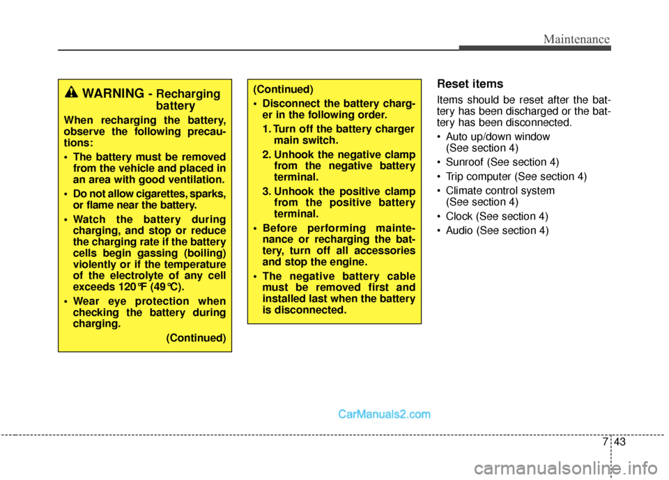
Items should be reset after the bat-
tery has been discharged or the bat-
tery has been disconnected.
Auto up/down window (See section 4)
Sunroof (See section 4)
Trip computer (See section 4)
Climate control system (See section 4)
Clock (See section 4)
Audio (See section 4)(Continued)
Disconnect the battery charg- er in the following order.
1. Turn off the battery charger main switch.
2. Unhook the negative clamp from the negative battery
terminal.
3. Unhook the positive clamp from the positive battery
terminal.
Before performing mainte- nance or recharging the bat-
tery, turn off all accessories
and stop the engine.
The negative battery cable must be removed first and
installed last when the battery
is disconnected.WARNING- Rechargingbattery
When recharging the battery,
observe the following precau-
tions:
The battery must be removed
from the vehicle and placed in
an area with good ventilation.
Do not allow cigarettes, sparks, or flame near the battery.
Watch the battery during charging, and stop or reduce
the charging rate if the battery
cells begin gassing (boiling)
violently or if the temperature
of the electrolyte of any cell
exceeds 120°F (49°C).
Wear eye protection when checking the battery during
charging.
(Continued)
Page 552 of 614

755
Maintenance
Cold Tire Pressure:The amount of
air pressure in a tire, measured in
pounds per square inch (psi) or kilo-
pascals (kPa) before a tire has built
up heat from driving.
Curb Weight: This means the weight
of a motor vehicle with standard and
optional equipment including the
maximum capacity of fuel, oil and
coolant, but without passengers and
cargo.
DOT Markings: A code molded into
the sidewall of a tire signifying that
the tire is in compliance with the U.S.
Department of Transportation motor
vehicle safety standards. The DOT
code includes the Tire Identification
Number (TIN), an alphanumeric des-
ignator which can also identify the
tire manufacturer, production plant,
brand and date of production.
GVWR: Gross Vehicle Weight Rating
GAWR FRT: Gross Axle Weight
Rating for the Front Axle.
GAWR RR: Gross Axle Weight
Rating for the Rear axle. Intended Outboard Sidewall:
The
side of an asymmetrical tire, that
must always face outward when
mounted on a vehicle.
Kilopascal (kPa): The metric unit for
air pressure.
Light truck(LT) tire: A tire designat-
ed by its manufacturer as primarily
intended for use on lightweight trucks
or multipurpose passenger vehicles.
Load ratings: The maximum load
that a tire is rated to carry for a given
inflation pressure.
Load Index: An assigned number
ranging from 1 to 279 that corre-
sponds to the load carrying capacity
of a tire.
Maximum Inflation Pressure: The
maximum air pressure to which a
cold tire may be inflated. The maxi-
mum air pressure is molded onto the
sidewall.
Maximum Load Rating: The load
rating for a tire at the maximum per-
missible inflation pressure for that tire.
Maximum Loaded Vehicle Weight:
The sum of curb weight; accessory
weight; vehicle capacity weight; and
production options weight. Normal Occupant Weight:
The
number of occupants a vehicle is
designed to seat multiplied by 150
pounds (68 kg).
Occupant Distribution: Designated
seating positions.
Outward Facing Sidewall: The side
of a asymmetrical tire that has a par-
ticular side that faces outward when
mounted on a vehicle. The outward
facing sidewall bears white lettering
or bears manufacturer, brand, and/or
model name molding that is higher or
deeper than the same moldings on
the inner facing sidewall.
Passenger (P-Metric) Tire: A tire
used on passenger cars and some
light duty trucks and multipurpose
vehicles.
Ply: A layer of rubber-coated parallel
cords
Pneumatic tire: A mechanical device
made of rubber, chemicals, fabric and
steel or other materials, that, when
mounted on an automotive wheel,
provides the traction and contains the
gas or fluid that sustains the load.
Page 557 of 614

Maintenance
60
7
FUSES
A vehicle’s electrical system is pro-
tected from electrical overload dam-
age by fuses. This vehicle has 2 fuse panels, one
located in the driver’s side panel bol-
ster, the other in the engine compart-
ment near the battery.
If any of your vehicle’s lights, acces-
sories, or controls do not work, check
the appropriate circuit fuse. If a fuse
has blown, the element inside the
fuse will be melted.
If the electrical system does not
work, first check the driver’s side
fuse panel.
Always replace a blown fuse with
one of the same rating.
Before replacing an open fuse, dis-
connect the negative battery cable.
If the replacement fuse blows, this
indicates an electrical problem. Avoid
using the system involved and imme-
diately consult an authorized
HYUNDAI dealer.
Three kinds of fuses are used: blade
type for lower amperage rating, car-tridge type, and multi fuse for higheramperage ratings.
✽ ✽ NOTICE
The actual fuse/relay panel label
may differ from equipped items.
OLM079051N
Normal
Normal
Blade type
Cartridge type
Multi fuse Blown
Blown
Normal Blown
Normal Blown
WARNING - Fuse
replacement
Never replace a fuse with any-
thing but another fuse of the
same rating.
A higher capacity fuse could cause damage and possibly a
fire.
Never install a wire or alu- minum foil instead of the
proper fuse - even as a tem-
porary repair. It may cause
extensive wiring damage and
a possible fire.
CAUTION
Do not use a screwdriver or anyother metal object to removefuses because it may cause ashort circuit and damage thesystem.
Page 568 of 614
771
Maintenance
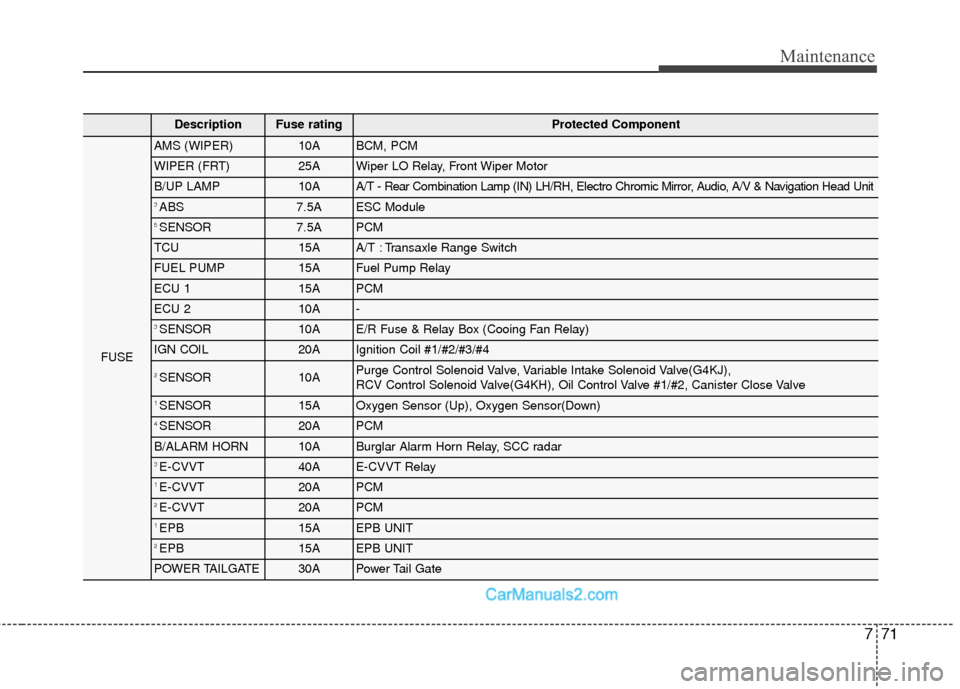
DescriptionFuse ratingProtected Component
FUSE
AMS (WIPER)10ABCM, PCM
WIPER (FRT)25AWiper LO Relay, Front Wiper Motor
B/UP LAMP10AA/T - Rear Combination Lamp (IN) LH/RH, Electro Chromic Mirror, Audio, A/V & Navigation Head Unit
3 ABS 7.5AESC Module
5 SENSOR7.5APCM
TCU15AA/T : Transaxle Range Switch
FUEL PUMP15AFuel Pump Relay
ECU 115APCM
ECU 210A-
3 SENSOR10AE/R Fuse & Relay Box (Cooing Fan Relay)
IGN COIL20AIgnition Coil #1/#2/#3/#4
2 SENSOR10APurge Control Solenoid Valve, Variable Intake Solenoid Valve(G4KJ),
RCV Control Solenoid Valve(G4KH), Oil Control Valve #1/#2, Canister Close Valve
1 SENSOR15AOxygen Sensor (Up), Oxygen Sensor(Down)
4 SENSOR20APCM
B/ALARM HORN10ABurglar Alarm Horn Relay, SCC radar
3 E-CVVT40AE-CVVT Relay
1 E-CVVT20APCM
2 E-CVVT20APCM
1 EPB15AEPB UNIT
2 EPB15AEPB UNIT
POWER TAILGATE30APower Tail Gate