ABS Hyundai Sonata
[x] Cancel search | Manufacturer: HYUNDAI, Model Year: , Model line: , Model:Pages: 285, PDF Size: 9.38 MB
Page 12 of 285
YOUR VEHICLE AT A GLANCE
F12
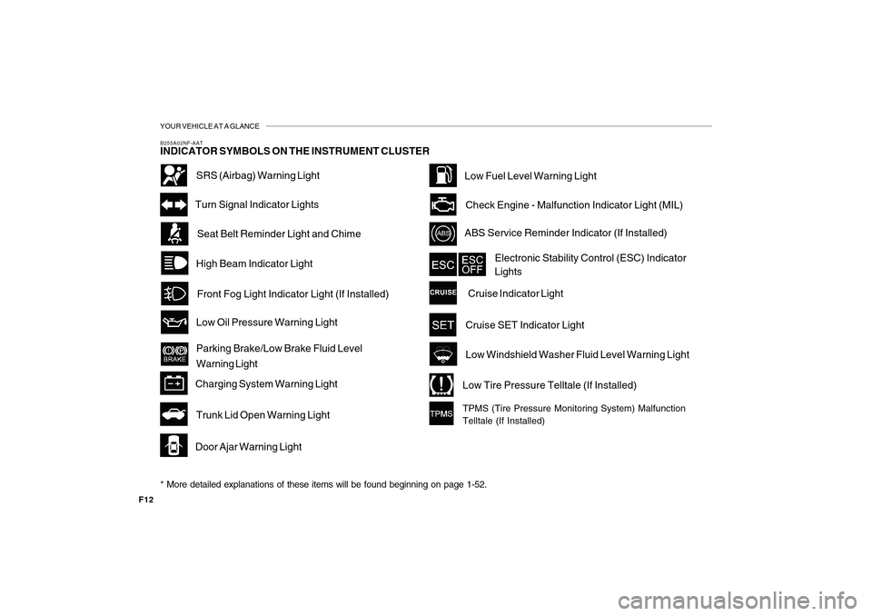
B255A02NF-AATINDICATOR SYMBOLS ON THE INSTRUMENT CLUSTER
High Beam Indicator Light
Door Ajar Warning LightSeat Belt Reminder Light and ChimeTurn Signal Indicator Lights
ABS Service Reminder Indicator (If Installed)
Low Oil Pressure Warning Light
Parking Brake/Low Brake Fluid Level
Warning Light
Charging System Warning Light
SRS (Airbag) Warning Light
Cruise Indicator Light Check Engine - Malfunction Indicator Light (MIL)
Electronic Stability Control (ESC) Indicator
Lights
Low Windshield Washer Fluid Level Warning LightFront Fog Light Indicator Light (If Installed)
Cruise SET Indicator LightLow Fuel Level Warning Light
Trunk Lid Open Warning Light
* More detailed explanations of these items will be found beginning on page 1-52.
Low Tire Pressure Telltale (If Installed)TPMS (Tire Pressure Monitoring System) Malfunction
Telltale (If Installed)
Page 16 of 285
1
FEATURES OF YOUR HYUNDAI
3
KEYS
BREAKING IN YOUR NEW
HYUNDAI
B010F01A-AATOperation in Foreign CountriesIf you are going to drive your Hyundai in
another country, be sure to:
o Observe all regulations regarding reg-
istration and insurance.
o Determine that acceptable fuel is
available.B010E01A-AATGasolines for Cleaner AirTo help contribute to cleaner air, Hyundai
recommends that you use gasolines
treated with detergent additives, which
help prevent deposit formation in the
engine. These gasolines will help the
engine run cleaner and enhance perfor-
mance of the Emission Control System.
B020A01S-AATDuring the First 1,200 Miles (1,931
Km)No formal "break-in" procedure is required
with your new Hyundai. However, you can
contribute to the economical operation
and durability of your Hyundai by observing
the following recommendations during the
first 1,200 miles (1,931 km).
o Don't drive faster than 55 MPH (88 km/
h).
o While driving, keep your engine speed
(rpm, or revolutions per minute) between
2,000 rpm and 4,000 rpm.
o Use moderate acceleration. Don't start
quickly or depress the accelerator pedal
fully.
o For the first 200 miles (322 km), try to
avoid hard stops.
o Don't lug the engine (in other words,
don't drive so slowly in too high a gear
that the engine "bucks":shift to a lower
gear).
o Whether going fast or slow, vary your
speed from time to time.
o Don't let the engine idle longer than 3
minutes at one time.
o Don't tow a trailer during the first 1,200
miles (1,931 km) of operation.
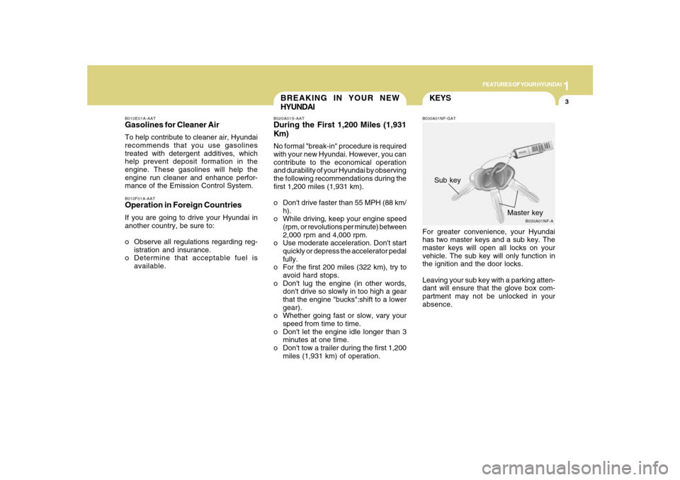
B030A01NF-GATFor greater convenience, your Hyundai
has two master keys and a sub key. The
master keys will open all locks on your
vehicle. The sub key will only function in
the ignition and the door locks.
Leaving your sub key with a parking atten-
dant will ensure that the glove box com-
partment may not be unlocked in your
absence.
B030A01NF-A
Master key Sub key
Page 44 of 285
1
FEATURES OF YOUR HYUNDAI
31
!
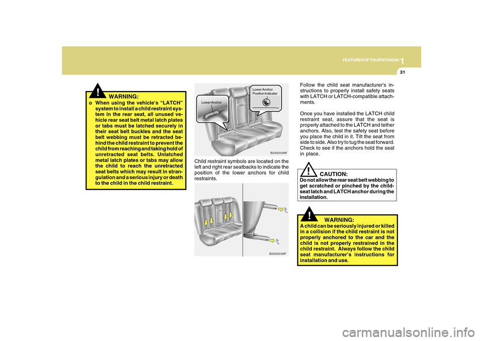
Child restraint symbols are located on the
left and right rear seatbacks to indicate the
position of the lower anchors for child
restraints.
B230D02NF
Lower AnchorLower Anchor
Position Indicator
B230D03NF
Follow the child seat manufacturer's in-
structions to properly install safety seats
with LATCH or LATCH-compatible attach-
ments.
Once you have installed the LATCH child
restraint seat, assure that the seat is
properly attached to the LATCH and tether
anchors. Also, test the safety seat before
you place the child in it. Tilt the seat from
side to side. Also try to tug the seat forward.
Check to see if the anchors hold the seat
in place.
!
o When using the vehicle’s “LATCH”
system to install a child restraint sys-
tem in the rear seat, all unused ve-
hicle rear seat belt metal latch plates
or tabs must be latched securely in
their seat belt buckles and the seat
belt webbing must be retracted be-
hind the child restraint to prevent the
child from reaching and taking hold of
unretracted seat belts. Unlatched
metal latch plates or tabs may allow
the child to reach the unretracted
seat belts which may result in stran-
gulation and a serious injury or death
to the child in the child restraint.
WARNING:
WARNING:
A child can be seriously injured or killed
in a collision if the child restraint is not
properly anchored to the car and the
child is not properly restrained in the
child restraint. Always follow the child
seat manufacturer’s instructions for
installation and use.
!
CAUTION:
Do not allow the rear seat belt webbing to
get scratched or pinched by the child-
seat latch and LATCH anchor during the
installation.
Page 64 of 285
1
FEATURES OF YOUR HYUNDAI
51
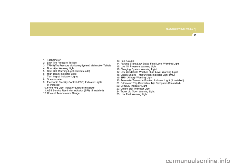
1. Tachometer
2. Low Tire Pressure Telltale
3. TPMS (Tire Pressure Monitoring System) Malfunction Telltale
4. Door Ajar Warning Light
5. Seat Belt Warning Light (Driver's side)
6. High Beam Indicator Light
7. Turn Signal Indicator Lights
8. Speedometer
9. Electronic Stability Control (ESC) Indicator Lights
(If Installed)
10. Front Fog Light Indicator Light (If Installed)
11. ABS Service Reminder Indicator (SRI) (If Installed)
12. Coolant Temperature Gauge13. Fuel Gauge
14. Parking Brake/Low Brake Fluid Level Warning Light
15. Low Oil Pressure Warning Light
16. Charging System Warning Light
17. Low Windshield Washer Fluid Level Warning Light
18. Check Engine - Malfunction Indicator Light (MIL)
19. SRS (Airbag) Warning Light
20. Automatic Transaxle Position Indicator Light (If Installed)
21. Odometer/ Trip Odometer/ Trip Computer (If Installed)
22. CRUISE Indicator Light
23. Cruise SET Indicator Light
24. Trunk Lid Open Warning Light
25. Low Fuel Warning Light
Page 68 of 285
1
FEATURES OF YOUR HYUNDAI
55
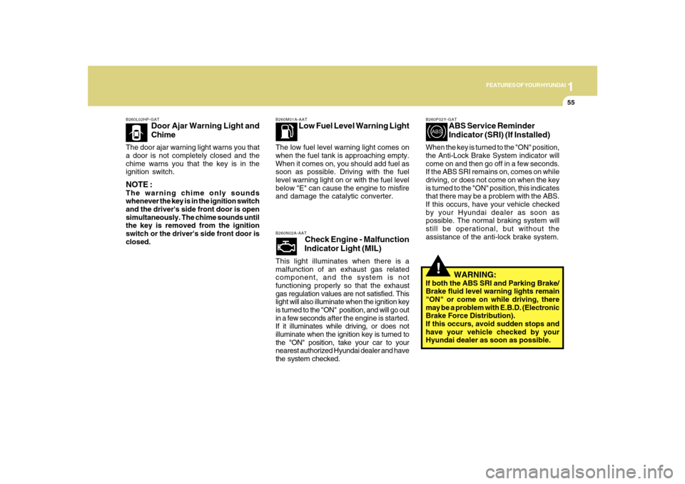
B260L02HP-GAT
Door Ajar Warning Light and
Chime
The door ajar warning light warns you that
a door is not completely closed and the
chime warns you that the key is in the
ignition switch.NOTE :The warning chime only sounds
whenever the key is in the ignition switch
and the driver's side front door is open
simultaneously. The chime sounds until
the key is removed from the ignition
switch or the driver's side front door is
closed.
B260M01A-AAT
Low Fuel Level Warning Light
The low fuel level warning light comes on
when the fuel tank is approaching empty.
When it comes on, you should add fuel as
soon as possible. Driving with the fuel
level warning light on or with the fuel level
below "E" can cause the engine to misfire
and damage the catalytic converter.B260N02A-AAT
Check Engine - Malfunction
Indicator Light (MIL)
This light illuminates when there is a
malfunction of an exhaust gas related
component, and the system is not
functioning properly so that the exhaust
gas regulation values are not satisfied. This
light will also illuminate when the ignition key
is turned to the "ON" position, and will go out
in a few seconds after the engine is started.
If it illuminates while driving, or does not
illuminate when the ignition key is turned to
the "ON" position, take your car to your
nearest authorized Hyundai dealer and have
the system checked.
!
B260P02Y-GAT
ABS Service Reminder
Indicator (SRI) (If Installed)
When the key is turned to the "ON" position,
the Anti-Lock Brake System indicator will
come on and then go off in a few seconds.
If the ABS SRI remains on, comes on while
driving, or does not come on when the key
is turned to the "ON" position, this indicates
that there may be a problem with the ABS.
If this occurs, have your vehicle checked
by your Hyundai dealer as soon as
possible. The normal braking system will
still be operational, but without the
assistance of the anti-lock brake system.
WARNING:
If both the ABS SRI and Parking Brake/
Brake fluid level warning lights remain
"ON" or come on while driving, there
may be a problem with E.B.D. (Electronic
Brake Force Distribution).
If this occurs, avoid sudden stops and
have your vehicle checked by your
Hyundai dealer as soon as possible.
Page 154 of 285
DRIVING YOUR HYUNDAI
2
Engine Exhaust Can Be Dangerous! ............................ 2-2
Before Starting the Engine ............................................ 2-3
Key Positions ................................................................ 2-4
Starting.........................................................................2-5
Operating the Manual Transaxle .................................. 2-6
Automatic Transaxle ..................................................... 2-8
Power Adjustable Pedals.............................................2-12
Anti-Lock Brake System (ABS) ...................................2-12
Electronic Stability Control (ESC) System ..................2-13
Good Braking Practices..............................................2-15
Driving for Economy....................................................2-16
Smooth Cornering........................................................2-17
Winter Driving..............................................................2-17
Trailer or Vehicle Towing .............................................2-20
Vehicle Load Limit........................................................2-24
2
Page 165 of 285
2
DRIVING YOUR HYUNDAI
12
!
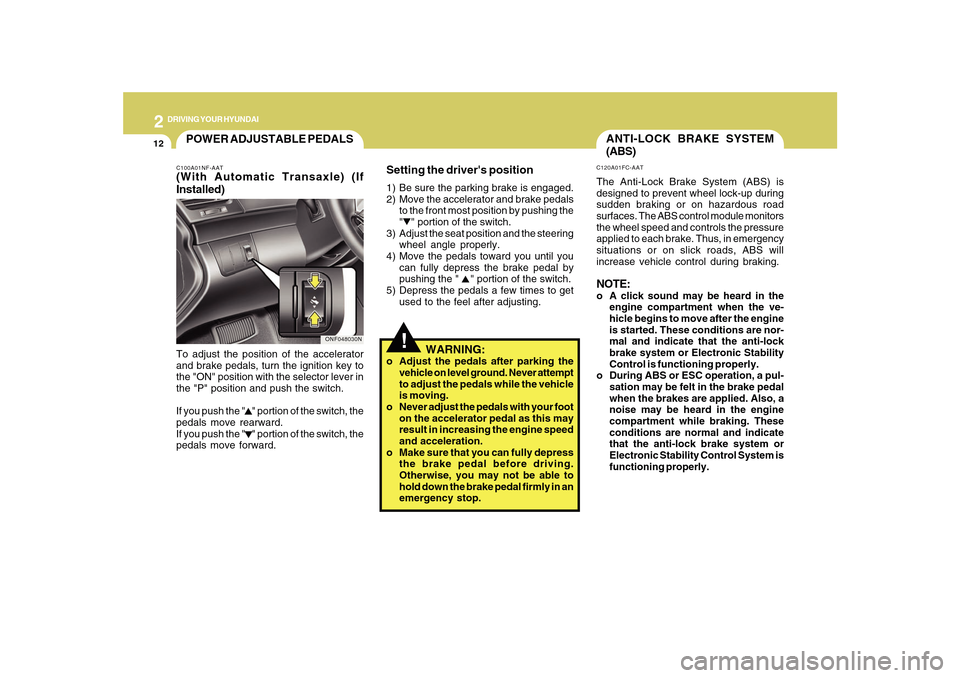
ANTI-LOCK BRAKE SYSTEM
(ABS)C120A01FC-AATThe Anti-Lock Brake System (ABS) is
designed to prevent wheel lock-up during
sudden braking or on hazardous road
surfaces. The ABS control module monitors
the wheel speed and controls the pressure
applied to each brake. Thus, in emergency
situations or on slick roads, ABS will
increase vehicle control during braking.NOTE:o A click sound may be heard in the
engine compartment when the ve-
hicle begins to move after the engine
is started. These conditions are nor-
mal and indicate that the anti-lock
brake system or Electronic Stability
Control is functioning properly.
o During ABS or ESC operation, a pul-
sation may be felt in the brake pedal
when the brakes are applied. Also, a
noise may be heard in the engine
compartment while braking. These
conditions are normal and indicate
that the anti-lock brake system or
Electronic Stability Control System is
functioning properly.
Setting the driver's position1) Be sure the parking brake is engaged.
2) Move the accelerator and brake pedals
to the front most position by pushing the
" " portion of the switch.
3) Adjust the seat position and the steering
wheel angle properly.
4) Move the pedals toward you until you
can fully depress the brake pedal by
pushing the " " portion of the switch.
5) Depress the pedals a few times to get
used to the feel after adjusting.
WARNING:
o Adjust the pedals after parking the
vehicle on level ground. Never attempt
to adjust the pedals while the vehicle
is moving.
o Never adjust the pedals with your foot
on the accelerator pedal as this may
result in increasing the engine speed
and acceleration.
o Make sure that you can fully depress
the brake pedal before driving.
Otherwise, you may not be able to
hold down the brake pedal firmly in an
emergency stop.
POWER ADJUSTABLE PEDALSC100A01NF-AAT(With Automatic Transaxle) (If
Installed)To adjust the position of the accelerator
and brake pedals, turn the ignition key to
the "ON" position with the selector lever in
the "P" position and push the switch.
If you push the " " portion of the switch, the
pedals move rearward.
If you push the " " portion of the switch, the
pedals move forward.
ONF048030N
Page 166 of 285
2
DRIVING YOUR HYUNDAI
13
!
!
WARNING:
ABS or ESC will not prevent accidents
due to improper or dangerous driving
maneuvers. Even though vehicle control
is improved during emergency braking,
always maintain a safe distance between
you and objects ahead. Vehicle speeds
should always be reduced during
extreme road conditions.
The braking distance for cars equipped
with an anti-lock braking system (Elec-
tronic Stability Control System) may be
longer than for those without it in the
following road conditions.
During these conditions the vehicle
should be driven at reduced speeds:
o Rough, gravel or snow-covered
roads.
o With tire chains installed.
o On roads where the road surface is
pitted or has different surface height.
The safety features of an ABS or ESC
equipped vehicle should not be tested by
high speed driving or cornering. This
could endanger the safety of yourself or
others.
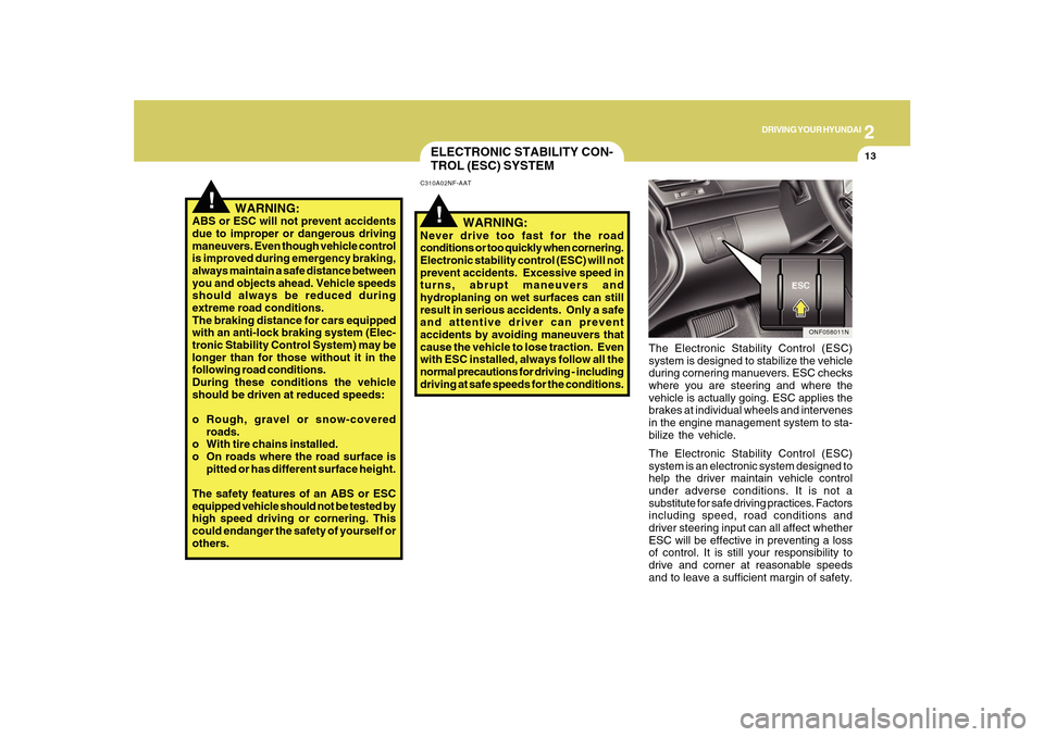
ELECTRONIC STABILITY CON-
TROL (ESC) SYSTEMC310A02NF-AAT
The Electronic Stability Control (ESC)
system is designed to stabilize the vehicle
during cornering manuevers. ESC checks
where you are steering and where the
vehicle is actually going. ESC applies the
brakes at individual wheels and intervenes
in the engine management system to sta-
bilize the vehicle.
The Electronic Stability Control (ESC)
system is an electronic system designed to
help the driver maintain vehicle control
under adverse conditions. It is not a
substitute for safe driving practices. Factors
including speed, road conditions and
driver steering input can all affect whether
ESC will be effective in preventing a loss
of control. It is still your responsibility to
drive and corner at reasonable speeds
and to leave a sufficient margin of safety.
ONF058011N
WARNING:
Never drive too fast for the road
conditions or too quickly when cornering.
Electronic stability control (ESC) will not
prevent accidents. Excessive speed in
turns, abrupt maneuvers and
hydroplaning on wet surfaces can still
result in serious accidents. Only a safe
and attentive driver can prevent
accidents by avoiding maneuvers that
cause the vehicle to lose traction. Even
with ESC installed, always follow all the
normal precautions for driving - including
driving at safe speeds for the conditions.
Page 202 of 285
4
CORROSION PREVENTION AND APPEARANCE CARE4
If you find any nicks or scratches in the
paint, use touch-up paint to cover them to
prevent corrosion. To protect the paintwork
of the car against corrosion, you must
clean your Hyundai (at least once a month).
Give special attention to the removal of
salt, mud and other substances on the
underside of the splashboards of the car.
Make sure that the outlets and the under-
side of the doors are open. Paint damage
can be caused by small accumulation of
tar, industrial precipitation, tree resin, in-
sects and bird droppings, when not re-
moved immediately. If water alone is not
strong enough to remove the accumulated
dirt, use a mild car washing solution. Be
sure to rinse the surface after washing to
remove the solution. Never allow the solu-
tion to dry on the painted surfaces. To clean whitewall tires, use a stiff brush or
soapy steel-wool scouring pad.
To clean plastic wheel covers, use a clean
sponge or soft cloth and water.
To clean cast aluminum alloy wheels, use
a mild soap or neutral detergent. Do not
use abrasive cleaners. Protect the bare-
metal surfaces by cleaning, polishing and
waxing. Because aluminum is subject to
corrosion, be sure to give aluminum alloy
wheels special attention in winter. If you
drive on salted roads, clean the wheels
thoroughly afterwards.
After washing, be sure to rinse thoroughly.
If soapy water dries on the finish, streaking
will result.
When the weather is warm and the humidity
low, you may find it necessary to rinse each
section immediately after washing to avoid
streaking.
After rinsing, dry the car using a damp
chamois or soft, absorbent cloth. The
reason for drying the car is to remove water
from the car so it will dry without water
spots. Don't rub, this can damage the finish.
CAUTION:
!
OJB037800
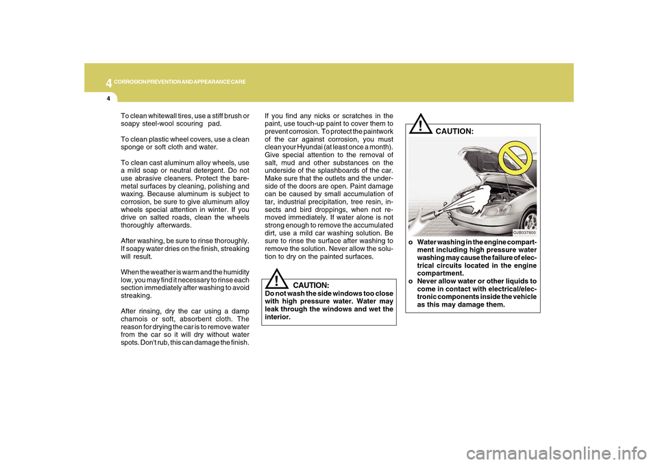
o Water washing in the engine compart-
ment including high pressure water
washing may cause the failure of elec-
trical circuits located in the engine
compartment.
o Never allow water or other liquids to
come in contact with electrical/elec-
tronic components inside the vehicle
as this may damage them.
!
CAUTION:
Do not wash the side windows too close
with high pressure water. Water may
leak through the windows and wet the
interior.
Page 252 of 285
6
DO-IT-YOURSELF MAINTENANCE
38
1
2
3
4
5
6
7
8
9
10
11
12
13
14
15
16
17
18
19
20
21
22
23
24
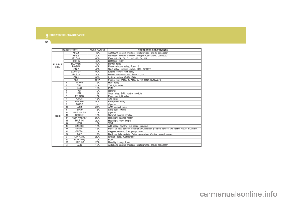
HORN
TAIL
ECU
IG1
DRL
FR FOG
A/CON
F/PUMP
DIODE
ATM
STOP
H/LP LO RH
S/ROOF
H/LP WASHER
H/LP HI
ECU
SNSR.3
SNSR.1
SNSR.2
B/UP
IGN COIL
ECU (IG1)
H/LP LO
ABS
PROTECTED COMPONENTS
ABS/ESC control module, Multipurpose check connector
ABS/ESC control module, Multipurpose check connector
Fuse 23, 24, 30, 31, 32, 33, 34, 35
Defogger relay
Blower relay
Power window relay, Fuse 16
Start relay, Ignition switch (IG2, START)
Engine control unit relay
Power connector 1/2, Fuse 21,22
Ignition switch (ACC, IG1)
Fusible Iink (ABS. 1, ABS. 2, RR HTD, BLOWER)
Horn relay
Tail light relay
PCM
(Spare)
Siren relay, DRL control module
Front fog light relay
A/C relay
Fuel pump relay
(Spare)
ATM control relay
Stop light switch
(Spare)
Sunroof control module
Headlight washer motor
Headlight relay (High)
TCM
A/C relay, Cooling fan relay, Injectors
Mass air flow sensor, Crankshaft/Camshaft position sensor, Oil control valve, SMATRA
Oxygen sensor, Fuel pump relay
Back up light switch, Pulse generator, Vehicle speed sensor
Ignition coils, Condenser
PCM
Headlight relay (Low)
ABS/ESC control module, Multipurpose check connector
ABS.1
ABS.2
I/P B+1
RR HTD
BLOWER
P/WDW
IGN.2
ECU RLY
I/P B+2
IGN.1
ALTFUSE RATING
40A
20A
40A
40A
40A
40A
40A
30A
30A
30A
150A
15A
20A
10A
10A
15A
15A
10A
20A
-
20A
15A
15A
15A
20A
20A
10A
10A
15A
15A
10A
20A
10A
20A
10A
DESCRIPTION
FUSIBLE
LINK
FUSE