flat tire Hyundai Sonata
[x] Cancel search | Manufacturer: HYUNDAI, Model Year: , Model line: , Model:Pages: 283, PDF Size: 13.5 MB
Page 186 of 283
3
WHAT TO DO IN AN EMERGENCY
9
!
SPARE TIRED040A03GK-AATTEMPORARY SPARE TIRE
The following instructions for the tem-
porary spare tire should be observed:
1. Check inflation pressure as soon as
practical after installing the spare
tire, and adjust to the specified pres-
sure. The tire pressure should be
periodically checked and maintained
at the specified pressure while the
tire is stored.Tire Size
Inflation Pressure
T125/80 D16
420 KPA(60 PSI)
4. As the temporary spare tire is spe-
cifically designed for your car, it
should not be used on any other
vehicle.
5. The temporary spare tire should not
be used on any other wheels, nor
should standard tires, snow tires,
wheel covers or trim rings be used
with the temporary spare wheel. If
such use is attempted, damage to
these items or other car components
may occur.
6. The temporary spare tire pressure
should be checked once a month
while the tire is stored.
2. The spare tire should only be used
temporarily and should be returned
to the luggage compartment as soon
as the original tire can be repaired or
replaced.
3. Continuous use at speeds of over 50
mph (80 km/h) is not recommended. Spare Tire Pressure
CAUTION:
o Do not use snow chains with your
temporary spare tire.
o Do not use more than one tempo-
rary spare tire at a time.
o Do not tow a trailer while the tem-
porary spare tire is installed.
!
WARNING:
The temporary spare tire is for emer-
gency use only. Do not operate your
vehicle on this temporary spare at
speeds over 50 mph (80 kmh). The
original tire should be repaired or
replaced as soon as is possible to
avoid failure of the spare possibly
leading to personal injury or death.
Page 187 of 283
310
WHAT TO DO IN AN EMERGENCY
CHANGING A FLAT TIRE
IF YOU HAVE A FLAT TIRE
D060A01A-AATThe procedure described on the follow-
ing pages can be used to rotate tires as
well as to change a flat tire. When
preparing to change a flat tire, check to
be sure the gear selector lever is in "P"
(automatic transaxle) or reverse gear
(manual transaxle) and that the parking
brake is set, then:
D050A01A-AATIf a tire goes flat while you are driving:
1. Take your foot off the accelerator pedal
and let the car slow down while driving
straight ahead. Do not apply the brakes
immediately or attempt to pull off the
road as this may cause a loss of
control. When the car has slowed to
such a speed that it is safe to do so,
brake carefully and pull off the road.
Drive off the road as far as possible
and park on firm, level ground. If you
are on a divided highway, do not park
in the median area between the two
traffic lanes.
2. When the car is stopped, turn on your
emergency hazard flashers, set the
parking brake and put the transaxle in
"P" (automatic) or reverse (manual
transaxle).
3. Have all passengers get out of the car.
Be sure they all get out on the side of
the car that is away from traffic.
4. Change the tire according to the in-
structions provided as follows.
D060A01NF-A
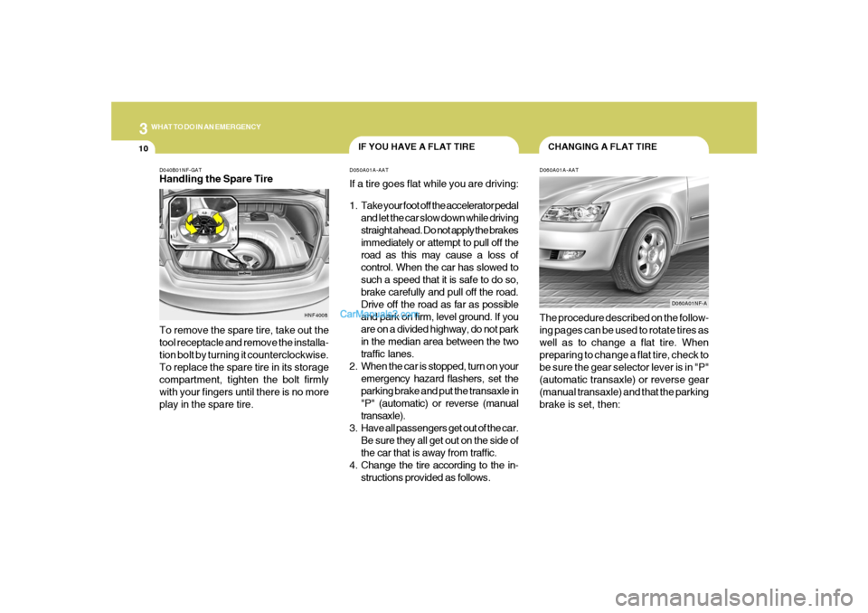
D040B01NF-GATHandling the Spare Tire
To remove the spare tire, take out the
tool receptacle and remove the installa-
tion bolt by turning it counterclockwise.
To replace the spare tire in its storage
compartment, tighten the bolt firmly
with your fingers until there is no more
play in the spare tire.
HNF4008
Page 188 of 283
3
WHAT TO DO IN AN EMERGENCY
11
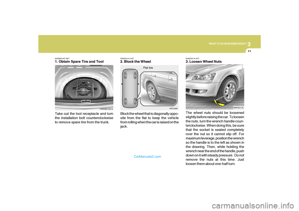
D060B01NF-GAT1. Obtain Spare Tire and Tool
7D060B01NF-A
Take out the tool receptacle and turn
the installation bolt counterclockwise
to remove spare tire from the trunk.
D060C01A-AAT2. Block the Wheel
Block the wheel that is diagonally oppo-
site from the flat to keep the vehicle
from rolling when the car is raised on the
jack.
HNF4009
Flat tire
D060D01A-AAT3. Loosen Wheel Nuts
The wheel nuts should be loosened
slightly before raising the car. To loosen
the nuts, turn the wrench handle coun-
terclockwise. When doing this, be sure
that the socket is seated completely
over the nut so it cannot slip off. For
maximum leverage, position the wrench
so the handle is to the left as shown in
the drawing. Then, while holding the
wrench near the end of the handle, push
down on it with steady pressure. Do not
remove the nuts at this time. Just
loosen them about one-half turn.
HNF4011-A
Page 189 of 283
312
WHAT TO DO IN AN EMERGENCY
!
Raise the car high enough so that the
fully inflated spare tire can be installed.
To do this, you will need more ground
clearance than is required to remove
the flat tire.
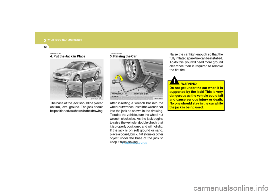
D060F02E-AAT5. Raising the Car
After inserting a wrench bar into the
wheel nut wrench, install the wrench bar
into the jack as shown in the drawing.
To raise the vehicle, turn the wheel nut
wrench clockwise. As the jack begins
to raise the vehicle, double check that
it is properly positioned and will not slip.
If the jack is on soft ground or sand,
place a board, brick, flat stone or other
object under the base of the jack to
keep it from sinking.WARNING:
Do not get under the car when it is
supported by the jack! This is very
dangerous as the vehicle could fall
and cause serious injury or death.
No one should stay in the car while
the jack is being used.
7HNF4025
Wrench bar Wheel nut
wrench
D060E01A-AAT4. Put the Jack in Place
The base of the jack should be placed
on firm, level ground. The jack should
be positioned as shown in the drawing.
D060E01NF-A
Page 190 of 283
3
WHAT TO DO IN AN EMERGENCY
13
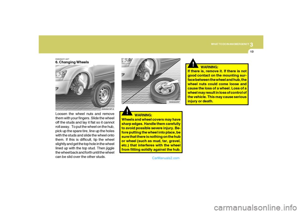
D060G02Y-AAT6. Changing Wheels
Loosen the wheel nuts and remove
them with your fingers. Slide the wheel
off the studs and lay it flat so it cannot
roll away. To put the wheel on the hub,
pick up the spare tire, line up the holes
with the studs and slide the wheel onto
them. If this is difficult, tip the wheel
slightly and get the top hole in the wheel
lined up with the top stud. Then jiggle
the wheel back and forth until the wheel
can be slid over the other studs.
D060G01NF-A
!
WARNING:
Wheels and wheel covers may have
sharp edges. Handle them carefully
to avoid possible severe injury. Be-
fore putting the wheel into place, be
sure that there is nothing on the hub
or wheel (such as mud, tar, gravel,
etc.) that interferes with the wheel
from fitting solidly against the hub.
D060G02NF
!
If there is, remove it. If there is not
good contact on the mounting sur-
face between the wheel and hub, the
wheel nuts could come loose and
cause the loss of a wheel. Loss of a
wheel may result in loss of control of
the vehicle. This may cause serious
injury or death.WARNING:
Page 192 of 283
3
WHAT TO DO IN AN EMERGENCY
15
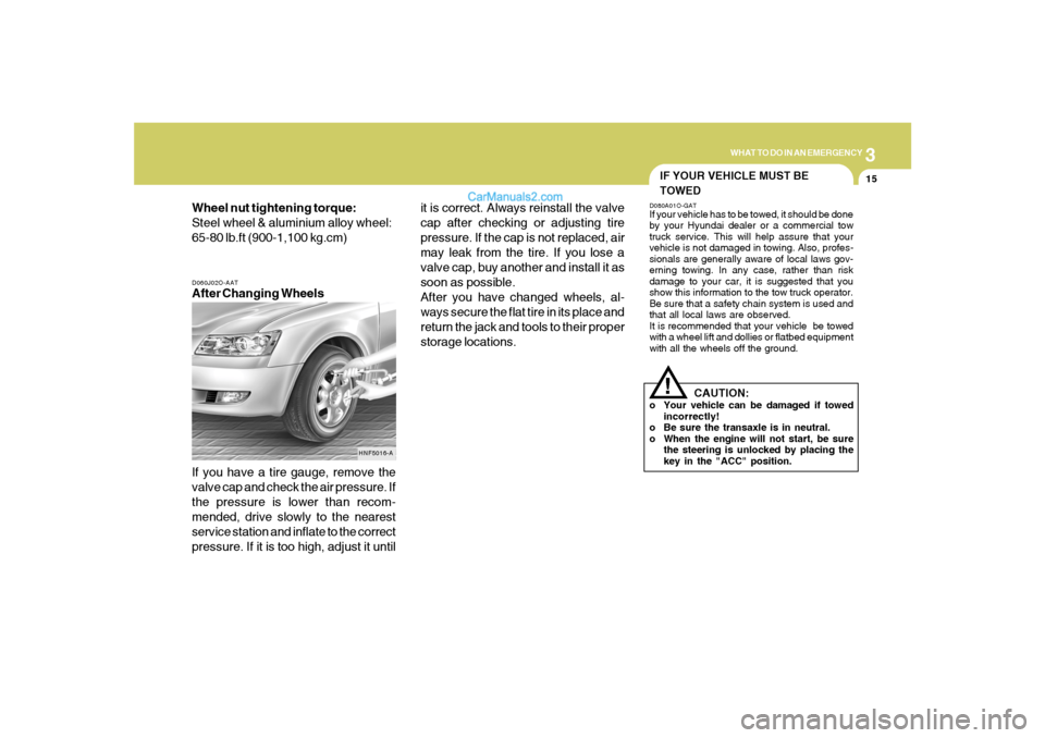
D060J02O-AATAfter Changing Wheels
If you have a tire gauge, remove the
valve cap and check the air pressure. If
the pressure is lower than recom-
mended, drive slowly to the nearest
service station and inflate to the correct
pressure. If it is too high, adjust it until Wheel nut tightening torque:
Steel wheel & aluminium alloy wheel:
65-80 lb.ft (900-1,100 kg.cm)
HNF5016-A
it is correct. Always reinstall the valve
cap after checking or adjusting tire
pressure. If the cap is not replaced, air
may leak from the tire. If you lose a
valve cap, buy another and install it as
soon as possible.
After you have changed wheels, al-
ways secure the flat tire in its place and
return the jack and tools to their proper
storage locations.
IF YOUR VEHICLE MUST BE
TOWEDD080A01O-GATIf your vehicle has to be towed, it should be done
by your Hyundai dealer or a commercial tow
truck service. This will help assure that your
vehicle is not damaged in towing. Also, profes-
sionals are generally aware of local laws gov-
erning towing. In any case, rather than risk
damage to your car, it is suggested that you
show this information to the tow truck operator.
Be sure that a safety chain system is used and
that all local laws are observed.
It is recommended that your vehicle be towed
with a wheel lift and dollies or flatbed equipment
with all the wheels off the ground.
!
CAUTION:
o Your vehicle can be damaged if towed
incorrectly!
o Be sure the transaxle is in neutral.
o When the engine will not start, be sure
the steering is unlocked by placing the
key in the "ACC" position.
Page 233 of 283
6
DO-IT-YOURSELF MAINTENANCE
22
Drive belts should be checked periodically for
proper tension. At the same time, belts should
be examined for cracks, wear, fraying or other
evidence of deterioration and replaced if neces-
sary.
When a new belt is replaced, the belt should be
located within the pulley of flat idler.
Belt routing should also be checked to be sure
there is no interference between the belts and
other parts of the engine.
NOTE:Drive belt tension is adjusted automatically
by the auto tensioner.
CHECKING AND REPLACING
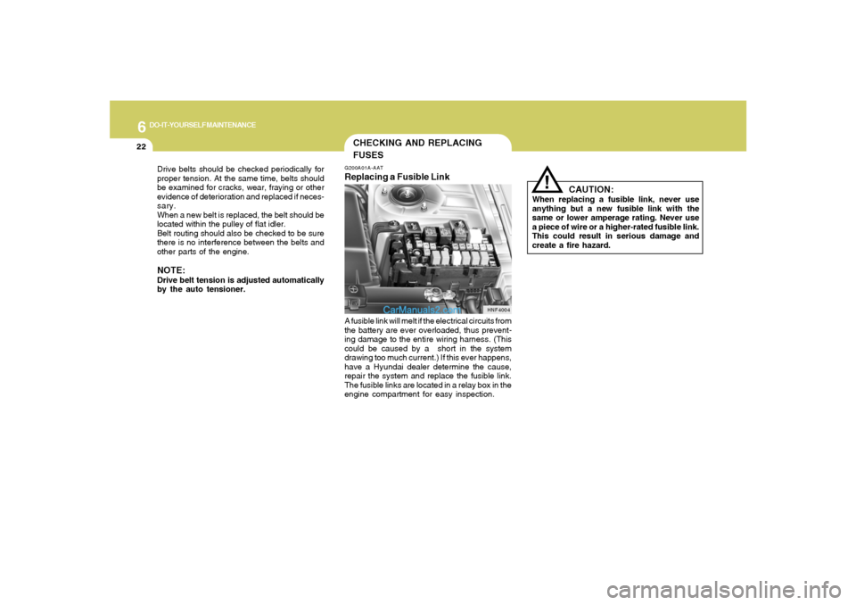
FUSESG200A01A-AATReplacing a Fusible LinkA fusible link will melt if the electrical circuits from
the battery are ever overloaded, thus prevent-
ing damage to the entire wiring harness. (This
could be caused by a short in the system
drawing too much current.) If this ever happens,
have a Hyundai dealer determine the cause,
repair the system and replace the fusible link.
The fusible links are located in a relay box in the
engine compartment for easy inspection.
HNF4004
!
CAUTION:
When replacing a fusible link, never use
anything but a new fusible link with the
same or lower amperage rating. Never use
a piece of wire or a higher-rated fusible link.
This could result in serious damage and
create a fire hazard.
Page 238 of 283
6
DO-IT-YOURSELF MAINTENANCE
27
HEADLIGHT AIMING ADJUSTMENTG290A03O-AATBefore performing aiming adjustment, make
sure of the following.
1. Keep all tires inflated to the correct pressure.
2. Place the vehicle on level ground and press
the front bumper & rear bumper down sev-
eral times.
Place vehicle at a distance of 118 in. (3m)
from the test wall.
3. See that the vehicle is unloaded (except for
full levels of coolant, engine oil and fuel, and
spare tire, jack, and tools). Have the driver
or equivalent weight placed in driver's seat.
4. Clean the headlight lenses and turn on the
headlights (Low beam).
5. Open the hood.
G290A01NF-A
Vertical
aiming
!
6. Draw a vertical line (through the center of
each headlight beam pattern) and a horizon-
tal line (through the center of each headlight
beam pattern) on the aiming screen.
And then, draw a parallel line at 0.8 in. (21
mm) under the horizontal line.
7. Adjust each cut-off line of the low beam to the
parallel line with a phillips screwdriver -
VERTICAL AIMING.
WARNING:
Never attempt to adjust the horizontal align-
ment of your headlights. Horizontal aiming
must be adjusted by an authorized Hyundai
dealer to avoid incorrect alignment that will
reduce the effectiveness of your headlights.
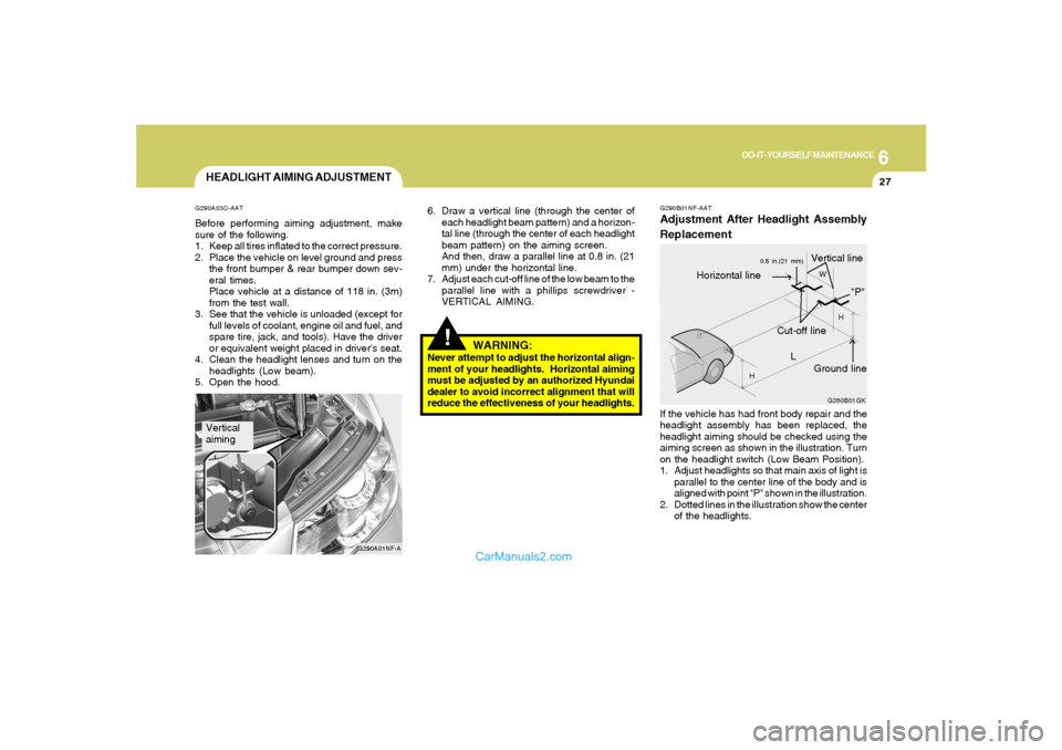
G290B01NF-AATAdjustment After Headlight Assembly
Replacement
G260B01GK
L
W
H
H
Cut-off line
Ground line
"P"
Horizontal line
Vertical line
0.8 in.(21 mm)
If the vehicle has had front body repair and the
headlight assembly has been replaced, the
headlight aiming should be checked using the
aiming screen as shown in the illustration. Turn
on the headlight switch (Low Beam Position).
1. Adjust headlights so that main axis of light is
parallel to the center line of the body and is
aligned with point "P" shown in the illustration.
2. Dotted lines in the illustration show the center
of the headlights.
Page 255 of 283
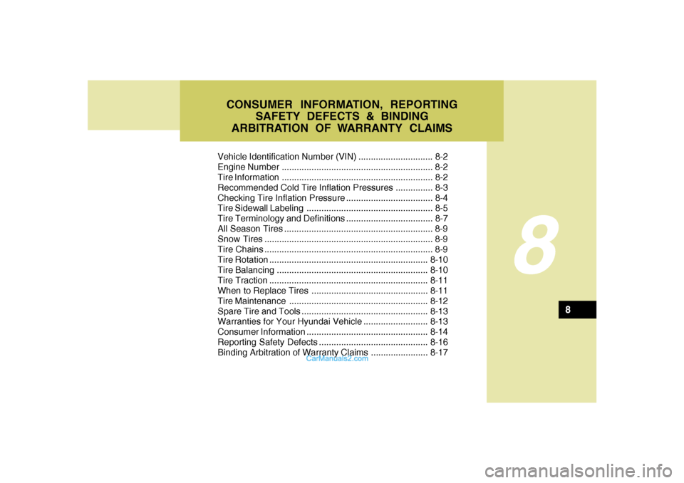
Vehicle Identification Number (VIN) .............................. 8-2
Engine Number ............................................................. 8-2
Tire Information ............................................................. 8-2
Recommended Cold Tire Inflation Pressures ............... 8-3
Checking Tire Inflation Pressure ................................... 8-4
Tire Sidewall Labeling ................................................... 8-5
Tire Terminology and Definitions ................................... 8-7
All Season Tires ............................................................ 8-9
Snow Tires .................................................................... 8-9
Tire Chains .................................................................... 8-9
Tire Rotation................................................................8-10
Tire Balancing.............................................................8-10
Tire Traction................................................................8-11
When to Replace Tires ...............................................8-11
Tire Maintenance........................................................8-12
Spare Tire and Tools ...................................................8-13
Warranties for Your Hyundai Vehicle..........................8-13
Consumer Information.................................................8-14
Reporting Safety Defects............................................8-16
Binding Arbitration of Warranty Claims.......................8-17
8
8
CONSUMER INFORMATION, REPORTING
SAFETY DEFECTS & BINDING
ARBITRATION OF WARRANTY CLAIMS
Page 257 of 283
8
CONSUMER INFORMATION, REPORTING SAFETY DEFECTS & BINDING ARBITRATION OF WARRANTY CLAIMS
3
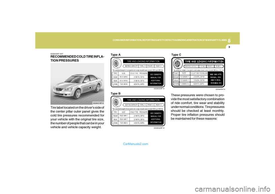
I030A03NF-AATRECOMMENDED COLD TIRE INFLA-
TION PRESSURES
Tire label located on the driver's side of
the center pillar outer panel gives the
cold tire pressures recommended for
your vehicle with the original tire size,
the number of people that can be in your
vehicle and vehicle capacity weight.These pressures were chosen to pro-
vide the most satisfactory combination
of ride comfort, tire wear and stability
under normal conditions. Tire pressures
should be checked at least monthly.
Proper tire inflation pressures should
be maintained for these reasons:
I030A01NF-A
I030A03NF-A
I030A04NF-A
Type A
Type B
i030a05nf-a
Type C