check Hyundai Sonata Turbo 2011 Manual Online
[x] Cancel search | Manufacturer: HYUNDAI, Model Year: 2011, Model line: Sonata Turbo, Model: Hyundai Sonata Turbo 2011Pages: 390, PDF Size: 8.44 MB
Page 334 of 390
739
Maintenance
Remove the valve cap from the tire
valve stem. Press the tire gage firm-
ly onto the valve to get a pressure
measurement. If the cold tire inflation
pressure matches the recommended
pressure on the tire and loading
information label, no further adjust-
ment is necessary. If the pressure is
low, add air until you reach the rec-
ommended amount.
If you overfill the tire, release air by
pushing on the metal stem in the
center of the tire valve. Recheck the
tire pressure with the tire gage. Be
sure to put the valve caps back on
the valve stems. They help prevent
leaks by keeping out dirt and mois-
ture.Tire rotation
To equalize tread wear, it is recom-
mended that the tires be rotated
every 7,500 miles (12,000 km) or
sooner if irregular wear develops.
During rotation, check the tires for
correct balance.
When rotating tires, check for uneven
wear and damage. Abnormal wear is
usually caused by incorrect tire pres-
sure, improper wheel alignment, out-
of-balance wheels, severe braking or
severe cornering. Look for bumps or
bulges in the tread or side of tire.
Replace the tire if you find either of
these conditions. Replace the tire if
fabric or cord is visible. After rotation,
be sure to bring the front and rear tire
pressures to specification and check
lug nut tightness.
WARNING
Inspect your tires frequently
for proper inflation as well as
wear and damage. Always use
a tire pressure gauge.
Tires with too much or too little pressure wear unevenly caus-
ing poor handling, loss of vehi-
cle control, and sudden tire
failure leading to accidents,
injuries, and even death. The
recommended cold tire pres-
sure for your vehicle can be
found in this manual and on
the tire label located on the dri-
ver's side center pillar.
Worn tires can cause acci- dents. Replace tires that are
worn, show uneven wear, or
are damaged.
Remember to check the pres- sure of your spare tire.
HYUNDAI recommends that
you check the spare every
time you check the pressure
of the other tires on your vehi-
cle.
YF HMA 7.qxp 8/24/2010 3:29 PM Page 39
Page 337 of 390
Maintenance42
7Compact spare tire replacement A compact spare tire has a shorter
tread life than a regular size tire.
Replace it when you can see the
tread wear indicator bars on the tire.
The replacement compact spare tire
should be the same size and design
tire as the one provided with your
new vehicle and should be mounted
on the same compact spare tire
wheel. The compact spare tire is not
designed to be mounted on a regular
size wheel, and the compact spare
tire wheel is not designed for mount-
ing a regular size tire. Wheel replacement
When replacing the metal wheels for
any reason, make sure the new
wheels are equivalent to the original
factory units in diameter, rim width
and offset.
Tire traction
Tire traction can be reduced if you
drive on worn tires, tires that are
improperly inflated or on slippery
road surfaces. Tires should be
replaced when tread wear indicators
appear. To reduce the possibility of
losing control, slow down whenever
there is rain, snow or ice on the road.
Tire maintenance
In addition to proper inflation, correct
wheel alignment helps to decrease
tire wear. If you find a tire is worn
unevenly, have your dealer check the
wheel alignment.
When you have new tires installed,
make sure they are balanced. This
will increase vehicle ride comfort and
tire life. Additionally, a tire should
always be rebalanced if it is removed
from the wheel.
WARNING
A wheel that is not the correct
size may adversely affect wheel
and bearing life, braking and
stopping abilities, handling char-
acteristics, ground clearance,
body-to-tire clearance, snow
chain clearance, speedometer
and odometer calibration, head-
light aim and bumper height.
YF HMA 7.qxp 8/24/2010 3:29 PM Page 42
Page 339 of 390
Maintenance44
7Tire speed ratings The chart below lists many of the dif-
ferent speed ratings currently being
used for passenger car tires. The
speed rating is part of the tire size
designation on the sidewall of the
tire. This symbol corresponds to that
tire's designed maximum safe oper-
ating speed.
3. Checking tire life (TIN : Tire
Identification Number) Any tires that are over 6 years old,
based on the manufacturing date,
(including the spare tire) should be
replaced by new ones. You can find
the manufacturing date on the tire
sidewall (possibly on the inside of the
wheel), displaying the DOT Code.
The DOT Code is a series of num-
bers on a tire consisting of numbers
and English letters. The manufactur-
ing date is designated by the last four
digits (characters) of the DOT code.
DOT : XXXX XXXX OOOO
The front part of the DOT means a
plant code number, tire size and
tread pattern and the last four num-
bers indicate week and year manu-
factured.
For example:
DOT XXXX XXXX 1610 represents
that the tire was produced in the 16th
week of 2010.
4. Tire ply composition and materialThe number of layers or plies of rub-
ber-coated fabric in the tire. Tire
manufacturers also must indicate the
materials in the tire, which include
steel, nylon, polyester, and others.
The letter "R" means radial ply con-
struction; the letter "D" means diago-
nal or bias ply construction; and the
letter "B" means belted-bias ply con-
struction.
S 112 mph (180 km/h)
T 118 mph (190 km/h)
H 130 mph (210 km/h) V 149 mph (240 km/h)Z Above 149 mph (240 km/h)
Maximum Speed
Speed
Rating
Symbol
WARNING - Tire age
Tires degrade over time, even
when they are not being used.
Regardless of the remaining
tread, it is recommended that
tires generally be replaced after
six (6) years of normal service.
Heat caused by hot climates or
frequent high loading condi-
tions can accelerate the aging
process. Failure to follow this
warning can result in sudden
tire failure, which could lead to
a loss of control and an acci-
dent involving serious injury or
death.
YF HMA 7.qxp 8/24/2010 3:29 PM Page 44
Page 345 of 390
Maintenance50
7FUSESA vehicle’s electrical system is protected
from electrical overload damage by
fuses. This vehicle has 2 fuse panels, one locat-
ed in the driver’s side panel bolster, the
other in the engine compartment.
If any of your vehicle’s lights, acces-
sories, or controls do not work, check the
appropriate circuit fuse. If a fuse has
blown, the element inside the fuse will be
melted.
If the electrical system does not work,
first check the driver’s side fuse panel.
Always replace a blown fuse with one of
the same rating.
If the replacement fuse blows, this indi-
cates an electrical problem. Avoid using
the system involved and immediately
consult an authorized HYUNDAI dealer.
Three kinds of fuses are used: blade type
for lower amperage rating, cartridge type,and multi fuse for higher amperage rat-ings.
OBK079042
Normal
Normal
Blade type
Cartridge type
Multi fuse Blown
Blown
Normal Blown
WARNING
- Fuse replace-
ment
Never replace a fuse with any-
thing but another fuse of the
same rating.
A higher capacity fuse could cause damage and possibly a
fire.
Never install a wire instead of the proper fuse - even as a temporary
repair. It may cause extensive
wiring damage and a possible fire.
CAUTION
Do not use a screwdriver or any
other metal object to remove fusesbecause it may cause a short circuit and damage the system.
YF HMA 7.qxp 8/24/2010 3:29 PM Page 50
Page 346 of 390
751
Maintenance
Instrument panel fuse replace-
ment1. Turn the ignition switch and all otherswitches off.
2. Open the fuse panel cover. 3. Pull the suspected fuse straight out.
Use the removal tool provided in the
engine compartment fuse panel.
4. Check the removed fuse; replace it if it is blown.
5. Push in a new fuse of the same rating, and make sure it fits tightly in the clips.
If it fits loosely, consult an authorized
HYUNDAI dealer.
If you do not have a spare, use a fuse of the same rating from a circuit you maynot need for operating the vehicle, such as the cigarette lighter fuse.
If the headlights or other electrical com-
ponents do not work and the fuses are
OK, check the fuse panel in the engine
compartment. If a fuse is blown, it must
be replaced.
OYF079020
OYF079021
YF HMA 7.qxp 8/24/2010 3:29 PM Page 51
Page 348 of 390
753
Maintenance
3. Check the removed fuse; replace it if itis blown. To remove or insert the fuse,
use the fuse puller in the engine com-
partment fuse panel.
4. Push in a new fuse of the same rating, and make sure it fits tightly in the clips.
If it fits loosely, consult an authorized
HYUNDAI dealer.
Multi fuseIf the multi fuse is blown, it must be
removed as follows:
1. Turn off the engine.
2. Disconnect the negative battery cable.
3. Remove the fuse panel on the rightside in the engine compartment.
4. Remove the nuts shown in the picture above.
5. Replace the fuse with a new one of the same rating.
6. Reinstall in the reverse order of removal.
✽ ✽NOTICEIf the multi fuse is blown, consult an
authorized HYUNDAI dealer.
CAUTION
After checking the fuse panel in the
engine compartment, securelyinstall the fuse panel cover. If not,electrical failures may occur from water contact.
OYF079024
YF HMA 7.qxp 8/24/2010 3:30 PM Page 53
Page 352 of 390
757
Maintenance
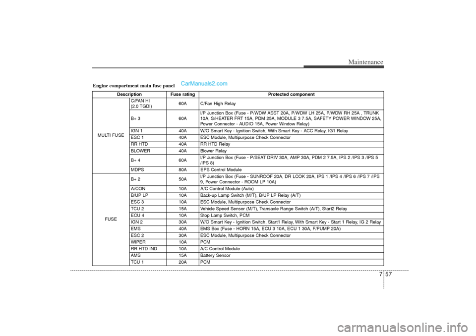
Engine compartment main fuse panel
DescriptionFuse rating Protected component
MULTI FUSE C/FAN HI
(2.0 TGDI)
60A C/Fan High Relay
B+ 3 60AI/P Junction Box (Fuse - P/WDW ASST 20A, P/WDW LH 25A, P/WDW RH 25A , TRUNK
10A, S/HEATER FRT 15A, PDM 25A, MODULE 3 7.5A, SAFETY POWER WINDOW 25A,
Power Connector - AUDIO 15A, Power Window Relay)
IGN 1 40A W/O Smart Key - Ignition Switch, With Smart Key - ACC Relay, IG1 Relay
ESC 1 40A ESC Module, Multipurpose Check Connector
RR HTD 40A RR HTD Relay
BLOWER 40A Blower Relay
B+ 4 60AI/P Junction Box (Fuse - P/SEAT DRIV 30A, AMP 30A, PDM 2 7.5A, IPS 2 /IPS 3 /IPS 5
/IPS 8)
MDPS
80A
EPS Control Module
FUSE B+ 2 50A
I/P Junction Box (Fuse - SUNROOF 20A, DR LCOK 20A, IPS 1 /IPS 4 /IPS 6 /IPS 7 /IPS
9, Power Connector - ROOM LP 10A)
A/CON
10A
A/C Control Module (Auto)
B/UP LP 10A Back-up Lamp Switch (M/T), B/UP LP Relay (A/T)
ESC 3 10A ESC Module, Multipurpose Check Connector
TCU 2 15A Vehicle Speed Sensor (M/T), Transaxle Range Switch (A/T), Start2 Relay
ECU 4 10A Stop Lamp Switch, PCM
IGN 2 30A W/O Smart Key - Ignition Switch, Start1 Relay, With Smart Key - Start 1 Relay, IG 2 Relay
EMS 40A EMS Box (Fuse - HORN 15A, ECU 3 10A, ECU 1 30A, F/PUMP 20A)
ESC 2 30A ESC Module, Multipurpose Check Connector
WIPER 10A PCM
RR HTD IND 10A A/C Control Module
AMS 15A Battery Sensor
TCU 1 20A PCM
YF HMA 7.qxp 8/24/2010 3:30 PM Page 57
Page 354 of 390
759
Maintenance
LIGHT BULBSUse only bulbs of the specified wattage.
✽
✽NOTICEAfter heavy, driving rain or washing,
headlight and taillight lenses could
appear frosty. This condition is caused by
the temperature difference between the
lamp inside and outside. This is similar
to the condensation on your windows
inside your vehicle during the rain and
doesn’t indicate a problem with your
vehicle. If the water leaks into the lamp
bulb circuitry, have the vehicle checked
by an authorized HYUNDAI dealer.
WARNING
- Working on
the lights
Prior to working on the light, firmly
apply the parking brake, ensure
that the ignition switch is turned to
the LOCK position and turn off the
lights to avoid sudden movement
of the vehicle and burning your fin-
gers or receiving an electric shock.
CAUTION
Be sure to replace the burned-out
bulb with one of the same wattage rating. Otherwise, it may causedamage to the fuse or electric wiring system.
CAUTION
If you don’t have necessary tools,the correct bulbs and the expertise,consult an authorized HYUNDAIdealer. In many cases, it is difficult to replace vehicle light bulbsbecause other parts of the vehiclemust be removed before you canget to the bulb. This is especially true if you have to remove the head-light assembly to
get to the bulb(s).
Removing/installing
the headlight
assembly can result in damage to the vehicle.
YF HMA 7.qxp 8/24/2010 3:30 PM Page 59
Page 356 of 390
761
Maintenance
1. Open the hood.
2. Remove the headlight bulb cover byturning it counterclockwise.
3. Disconnect the headlight bulb socket- connector.
4. Unsnap the headlight bulb retaining wire by depressing the end and push-
ing it upward.
5. Remove the bulb from the headlight assembly.
6. Install a new headlight bulb and snap the headlight bulb retaining wire into
position by aligning the wire with the
groove on the bulb.
7. Connect the headlight bulb socket- connector.
8. Install the headlight bulb cover by turn- ing it clockwise.
✽ ✽NOTICEIf the headlight aiming adjustment is
necessary after the headlight assembly is
reinstalled, consult an authorized
HYUNDAI dealer.G220102ABH-EUFront turn signal, position, side mark-
er and fog light bulbs (if equipped)If the light bulb is not operating, have the
vehicle checked by an authorized
HYUNDAI dealer.
Side repeater light bulb replace-
ment (if equipped)If the light bulb is not operating, have the
vehicle checked by an authorized
HYUNDAI dealer.
OYF079041
OYF079045
YF HMA 7.qxp 8/24/2010 3:31 PM Page 61
Page 357 of 390
Maintenance62
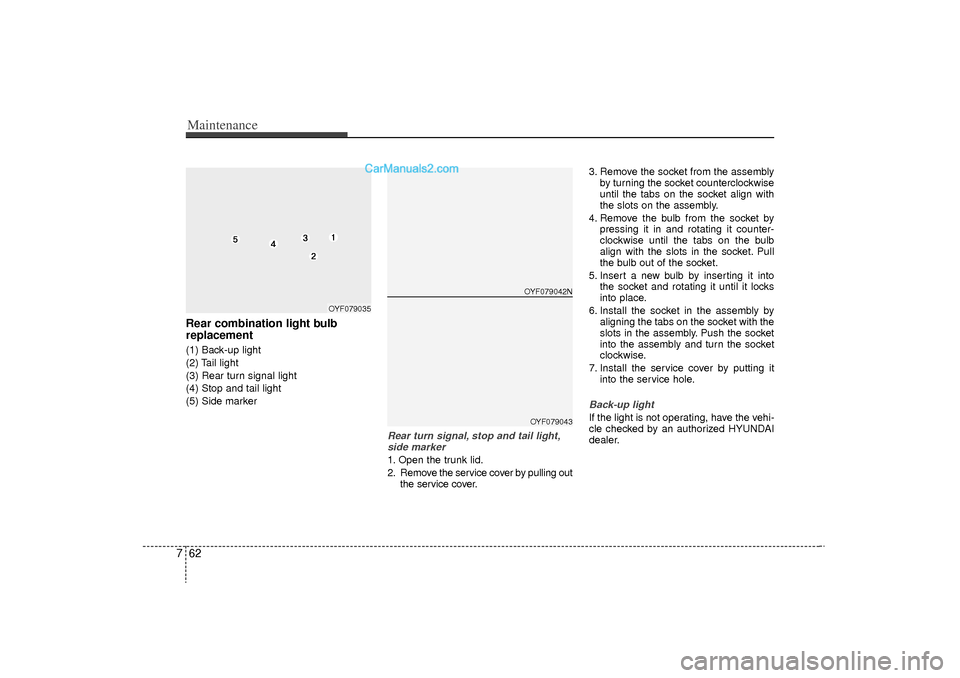
7Rear combination light bulb
replacement(1) Back-up light
(2) Tail light
(3) Rear turn signal light
(4) Stop and tail light
(5) Side marker
Rear turn signal, stop and tail light,
side marker1. Open the trunk lid.
2. Remove the service cover by pulling out the service cover. 3. Remove the socket from the assembly
by turning the socket counterclockwise
until the tabs on the socket align with
the slots on the assembly.
4. Remove the bulb from the socket by pressing it in and rotating it counter-
clockwise until the tabs on the bulb
align with the slots in the socket. Pull
the bulb out of the socket.
5. Insert a new bulb by inserting it into the socket and rotating it until it locks
into place.
6. Install the socket in the assembly by aligning the tabs on the socket with the
slots in the assembly. Push the socket
into the assembly and turn the socket
clockwise.
7. Install the service cover by putting it into the service hole.
Back-up lightIf the light is not operating, have the vehi-
cle checked by an authorized HYUNDAI
dealer.
OYF079042N
OYF079035
OYF079043
YF HMA 7.qxp 8/24/2010 3:31 PM Page 62