low beam Hyundai Terracan 2005 Owner's Manual
[x] Cancel search | Manufacturer: HYUNDAI, Model Year: 2005, Model line: Terracan, Model: Hyundai Terracan 2005Pages: 539, PDF Size: 18.03 MB
Page 14 of 539
YOUR VEHICLE AT A GLANCE
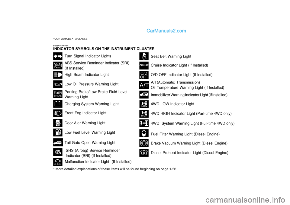
B255A01HP-GAT INDICATOR SYMBOLS ON THE INSTRUMENT CLUSTER
Turn Signal Indicator Lights
ABS Service Reminder Indicator (SRI) (If Installed) High Beam Indicator Light Low Oil Pressure Warning Light Parking Brake/Low Brake Fluid Level Warning Light Charging System Warning Light
Tail Gate Open Warning Light
Door Ajar Warning Light Low Fuel Level Warning Light
Front Fog Indicator Light
O/D OFF Indicator Light (If Installed)
Immobilizer Warning Indicator Light (If Installed)
SRS (Airbag) Service Reminder Indicator (SRI) (If Installed) Seat Belt Warning Light Cruise Indicator Light (If Installed)
Malfunction Indicator Light (If Installed)
A/T(Automatic Transmission) Oil Temperature Warning Light (If Installed)
4WD LOW Indicator Light 4WD HIGH Indicator Light (Part-time 4WD only)
4WD System Warning Light (Full-time 4WD only)
Fuel Filter Warning Light (Diesel Engine)
Brake Vacuum Warning Light (Diesel Engine)
* More detailed explanations of these items will be found beginning on page 1-58.
Diesel Preheat Indicator Light (Diesel Engine)
Page 69 of 539
1
FEATURES OF YOUR HYUNDAI
55
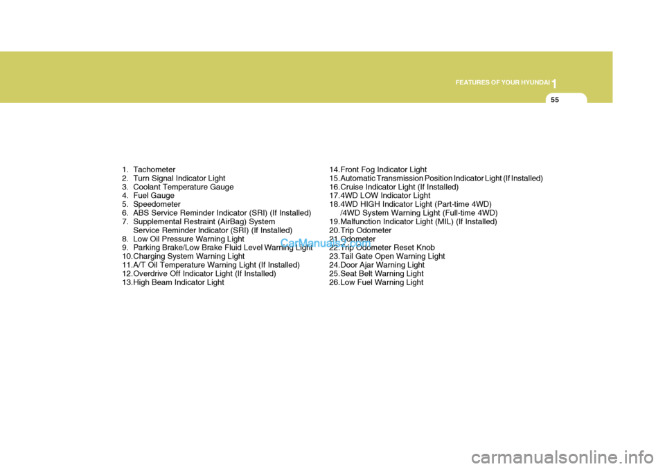
1. Tachometer
2. Turn Signal Indicator Light
3. Coolant Temperature Gauge
4. Fuel Gauge
5. Speedometer
6. ABS Service Reminder Indicator (SRI) (If Installed)
7. Supplemental Restraint (AirBag) System Service Reminder lndicator (SRI) (If Installed)
8. Low Oil Pressure Warning Light
9. Parking Brake/Low Brake Fluid Level Warning Light
10.Charging System Warning Light
11.A/T Oil Temperature Warning Light (If Installed)
12.Overdrive Off Indicator Light (If Installed)
13.High Beam Indicator Light 14.Front Fog Indicator Light
15.Automatic Transmission Position Indicator Light (If Installed)
16.Cruise Indicator Light (If Installed)
17.4WD LOW Indicator Light
18.4WD HIGH Indicator Light (Part-time 4WD)
/4WD System Warning Light (Full-time 4WD)
19.Malfunction Indicator Light (MIL) (If Installed)
20.Trip Odometer
21.Odometer 22.Trip Odometer Reset Knob
23.Tail Gate Open Warning Light
24.Door Ajar Warning Light
25.Seat Belt Warning Light
26.Low Fuel Warning Light
Page 71 of 539
1
FEATURES OF YOUR HYUNDAI
57
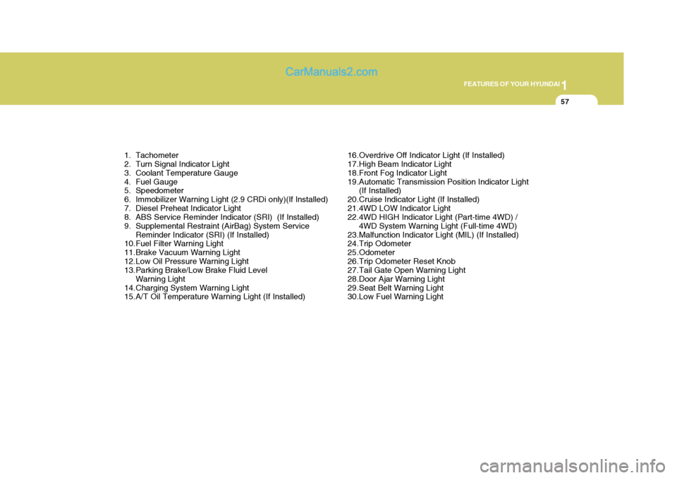
1. Tachometer
2. Turn Signal Indicator Light
3. Coolant Temperature Gauge
4. Fuel Gauge
5. Speedometer
6. Immobilizer Warning Light (2.9 CRDi only)(If Installed)
7. Diesel Preheat Indicator Light
8. ABS Service Reminder Indicator (SRI) (If Installed)
9. Supplemental Restraint (AirBag) System Service Reminder Indicator (SRI) (If Installed)
10.Fuel Filter Warning Light
11.Brake Vacuum Warning Light
12.Low Oil Pressure Warning Light
13.Parking Brake/Low Brake Fluid Level
Warning Light
14.Charging System Warning Light
15.A/T Oil Temperature Warning Light (If Installed) 16.Overdrive Off Indicator Light (If Installed)
17.High Beam Indicator Light
18.Front Fog Indicator Light
19.Automatic Transmission Position Indicator Light
(If Installed)
20.Cruise Indicator Light (If Installed)
21.4WD LOW Indicator Light
22.4WD HIGH Indicator Light (Part-time 4WD) / 4WD System Warning Light (Full-time 4WD)
23.Malfunction Indicator Light (MIL) (If Installed)
24.Trip Odometer
25.Odometer
26.Trip Odometer Reset Knob
27.Tail Gate Open Warning Light
28.Door Ajar Warning Light
29.Seat Belt Warning Light
30.Low Fuel Warning Light
Page 72 of 539
1FEATURES OF YOUR HYUNDAI
58WARNING AND INDICATOR LIGHTS
!
B260D01A-AAT
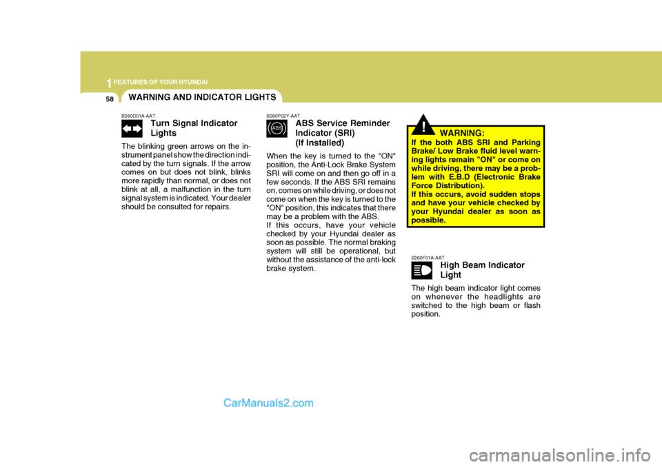
Turn Signal Indicator Lights
The blinking green arrows on the in- strument panel show the direction indi-cated by the turn signals. If the arrow comes on but does not blink, blinks more rapidly than normal, or does notblink at all, a malfunction in the turn signal system is indicated. Your dealer should be consulted for repairs. B260P02Y-AAT
ABS Service Reminder Indicator (SRI)(If Installed)
When the key is turned to the "ON" position, the Anti-Lock Brake System SRI will come on and then go off in afew seconds. If the ABS SRI remains on, comes on while driving, or does not come on when the key is turned to the"ON" position, this indicates that there may be a problem with the ABS. If this occurs, have your vehiclechecked by your Hyundai dealer as soon as possible. The normal braking system will still be operational, butwithout the assistance of the anti-lock brake system. WARNING:
If the both ABS SRI and ParkingBrake/ Low Brake fluid level warn- ing lights remain "ON" or come onwhile driving, there may be a prob- lem with E.B.D (Electronic Brake Force Distribution).If this occurs, avoid sudden stops and have your vehicle checked by your Hyundai dealer as soon aspossible. B260F01A-AAT High Beam Indicator Light
The high beam indicator light comes on whenever the headlights areswitched to the high beam or flash position.
Page 88 of 539
1FEATURES OF YOUR HYUNDAI
74
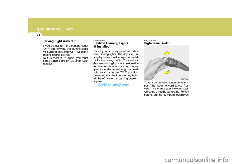
B340F01A-GAT Daytime Running Lights (If Installed) Your Hyundai is equipped with day- time running lights. The daytime run-ning lights are used to improve visibil- ity for oncoming traffic. Your vehicle daytime running lights are designed toremain on continuously when the en- gine is operating even though the head- light switch is in the "OFF" position.However, the daytime running lights will be off while the parking brake is applied. B340D01A-AAT High-beam Switch
Parking Light Auto Cut If you do not turn the parking lights "OFF" after driving, the parking lightswill automatically shut "OFF" when the driver's door is opened. To turn them "ON" again, you mustsimply turn the ignition key to the "ON" position.
To turn on the headlight high beams,push the lever forward (away from you). The High Beam Indicator Lightwill come on at the same time. For low beams, pull the lever back toward you.HHP2097
Page 113 of 539
1
FEATURES OF YOUR HYUNDAI
99HEADLIGHT LEVELING DE- VICE SYSTEMSTEERING WHEEL TILT LEVERREAR SEAT ARMREST
!
B611A01HP-AAT (If Installed) The rear seat armrest is located in the center of the rear seatback. A storage box and two drink holders are includedfor convenience. B600A01HP-GAT (If Installed) To adjust the steering wheel:
1. Pull the lever toward you and hold it
to unlock.
2. Raise or lower the steering wheel to
the desired position.
3. After adjustment, release the lever.
WARNING:
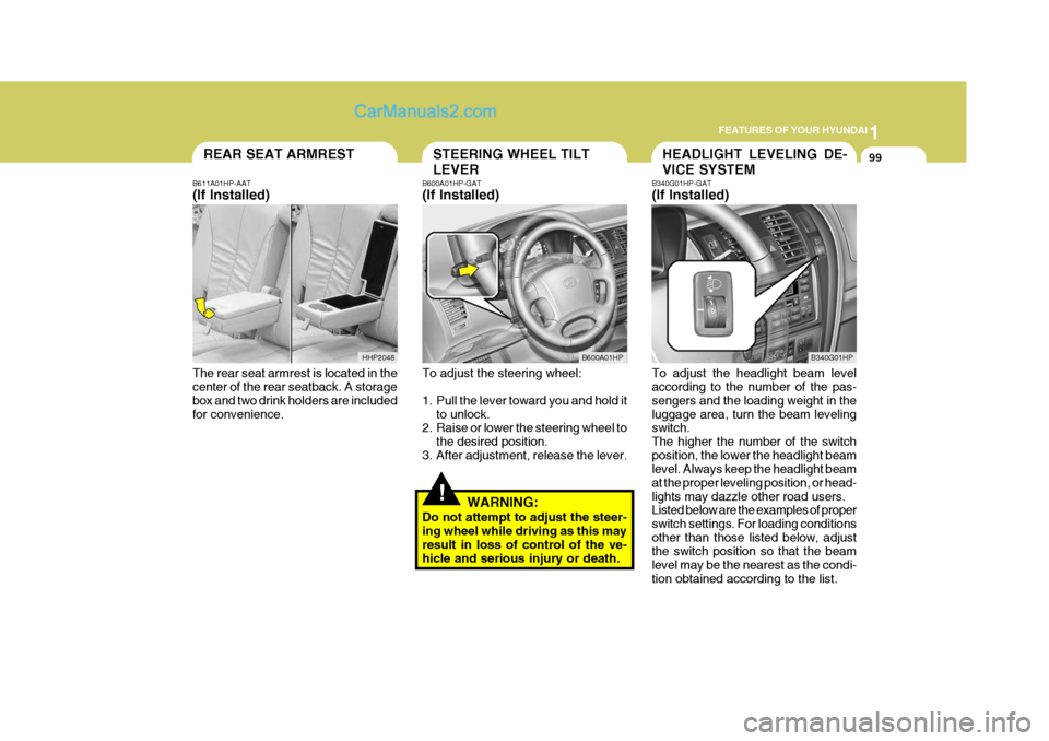
Do not attempt to adjust the steer- ing wheel while driving as this may result in loss of control of the ve- hicle and serious injury or death. B340G01HP-GAT (If Installed) To adjust the headlight beam level according to the number of the pas- sengers and the loading weight in theluggage area, turn the beam leveling switch. The higher the number of the switchposition, the lower the headlight beam level. Always keep the headlight beam at the proper leveling position, or head-lights may dazzle other road users. Listed below are the examples of proper switch settings. For loading conditionsother than those listed below, adjust the switch position so that the beam level may be the nearest as the condi-tion obtained according to the list.
B600A01HP
B340G01HP
HHP2048
Page 183 of 539
2 DRIVING YOUR HYUNDAI
28
C190B01S-AAT Trailer Hitches Select the proper hitch and ball combi- nation, making sure that it's location is compatible with that of the trailer or vehicle being towed.Use a quality non-equalizing hitch which distributes the tongue load uniformly throughout the chassis. The hitch should be bolted securely to the car and installed by a qualifiedtechnician. DO NOT USE A HITCH DESIGNED FOR TEMPORARY IN- STALLATION AND NEVER USE ONETHAT ATTACHES ONLY TO THE BUMPER.TRAILER OR VEHICLE TOWING
!
C190A01HP-GAT If you are considering towing with your car, you should first check with your Province Department of Motor Vehicles to determine their legal requirements.Since laws vary from province to prov- ince the requirements for towing trail- ers, cars, or other types of vehicles orapparatus may differ. Ask your Hyundai dealer for further details before towing.
CAUTION:
Do not do any towing with your carduring its first 2,000 km (1,200 miles) in order to allow the engine to prop-erly break in. Failure to heed this caution may result in serious en- gine or transmission damage.
USE OF LIGHTS
C180A01A-AAT Check your lights regularly for correct operation and always keep them clean. When driving during the day in condi- tions of poor visibility, it is helpful todrive with headlights on low beam. This enables you to be seen as well as to see.
Page 262 of 539
6 DO-IT-YOURSELF MAINTENANCE
40HEADLIGHT AIMING AD- JUSTMENT
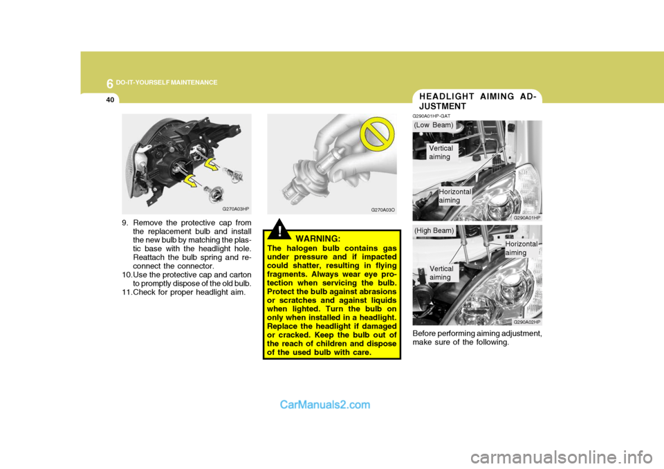
G290A01HP-GAT
G290A01HP G290A02HP
Before performing aiming adjustment,
make sure of the following.
!WARNING:
The halogen bulb contains gas
under pressure and if impacted could shatter, resulting in flyingfragments. Always wear eye pro- tection when servicing the bulb. Protect the bulb against abrasionsor scratches and against liquids when lighted. Turn the bulb on only when installed in a headlight.Replace the headlight if damaged or cracked. Keep the bulb out of the reach of children and disposeof the used bulb with care.
G270A03HP
9. Remove the protective cap from the replacement bulb and install the new bulb by matching the plas- tic base with the headlight hole.Reattach the bulb spring and re- connect the connector.
10.Use the protective cap and carton to promptly dispose of the old bulb.
11.Check for proper headlight aim. G270A03O(Low Beam)
(High Beam)
Vertical aiming
Horizontal aiming
Vertical aiming
Horizontal aiming
Page 263 of 539
6
DO-IT-YOURSELF MAINTENANCE
41
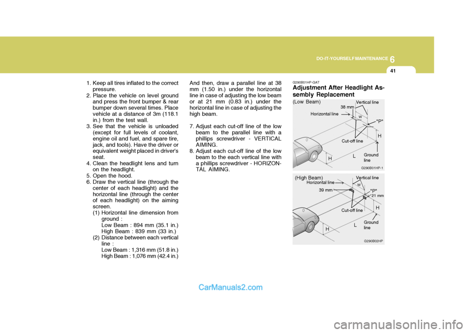
1. Keep all tires inflated to the correct
pressure.
2. Place the vehicle on level ground and press the front bumper & rear bumper down several times. Placevehicle at a distance of 3m (118.1 in.) from the test wall.
3. See that the vehicle is unloaded (except for full levels of coolant, engine oil and fuel, and spare tire,jack, and tools). Have the driver or equivalent weight placed in driver's seat.
4. Clean the headlight lens and turn on the headlight.
5. Open the hood.
6. Draw the vertical line (through the center of each headlight) and thehorizontal line (through the center of each headlight) on the aiming screen.
(1) Horizontal line dimension from
ground : Low Beam : 894 mm (35.1 in.) High Beam : 839 mm (33 in.)
(2) Distance between each vertical line : Low Beam : 1,316 mm (51.8 in.) High Beam : 1,076 mm (42.4 in.) And then, draw a parallel line at 38
mm (1.50 in.) under the horizontalline in case of adjusting the low beam or at 21 mm (0.83 in.) under the horizontal line in case of adjusting thehigh beam.
7. Adjust each cut-off line of the low beam to the parallel line with a phillips screwdriver - VERTICALAIMING.
8. Adjust each cut-off line of the low beam to the each vertical line witha phillips screwdriver - HORIZON- TAL AIMING. G290B01HP-GAT Adjustment After Headlight As- sembly Replacement
G290B02HP
LW
H Cut-off line
"P"
Vertical line
Horizontal line
Ground line
21 mm39 mm
(High Beam)
H
G290B01HP-1
LW
"P"
38 mm
H
H
(Low Beam)
Vertical line
Ground line
Cut-off line
Horizontal line
Page 264 of 539
6 DO-IT-YOURSELF MAINTENANCE
42
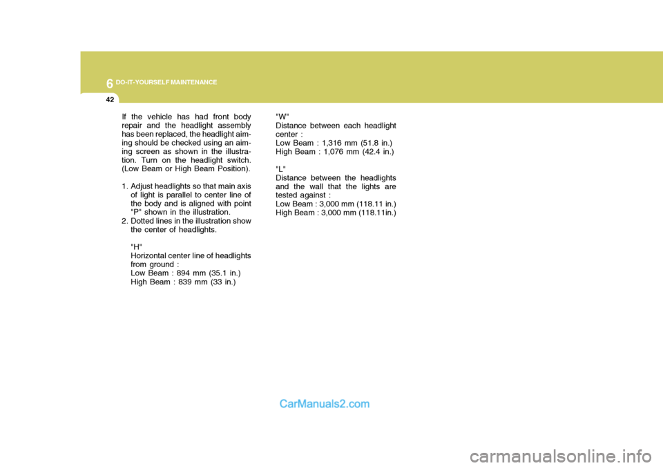
"W" Distance between each headlight center :Low Beam : 1,316 mm (51.8 in.) High Beam : 1,076 mm (42.4 in.) "L" Distance between the headlightsand the wall that the lights are tested against : Low Beam : 3,000 mm (118.11 in.) High Beam : 3,000 mm (118.11in.)
If the vehicle has had front body
repair and the headlight assemblyhas been replaced, the headlight aim- ing should be checked using an aim- ing screen as shown in the illustra-tion. Turn on the headlight switch. (Low Beam or High Beam Position).
1. Adjust headlights so that main axis of light is parallel to center line of the body and is aligned with point "P" shown in the illustration.
2. Dotted lines in the illustration show the center of headlights. "H" Horizontal center line of headlightsfrom ground :Low Beam : 894 mm (35.1 in.) High Beam : 839 mm (33 in.)