open bonnet Hyundai Terracan 2005 Owner's Manual
[x] Cancel search | Manufacturer: HYUNDAI, Model Year: 2005, Model line: Terracan, Model: Hyundai Terracan 2005Pages: 539, PDF Size: 18.03 MB
Page 317 of 539
1CONTROLS AND EQUIPMENT
12
!
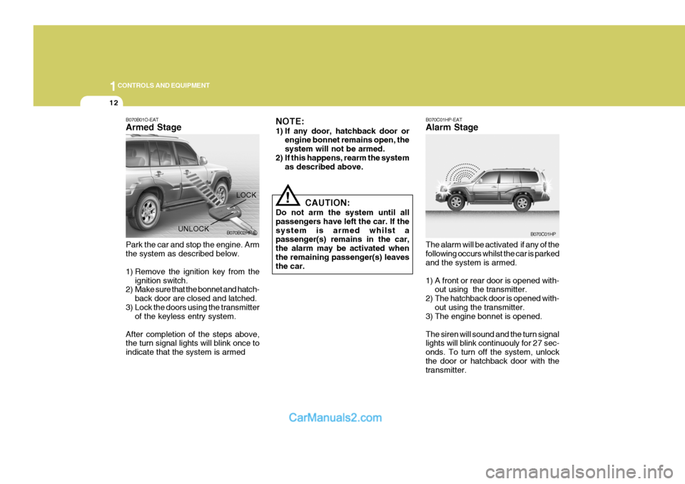
B070B01O-EAT Armed Stage
NOTE:
1) If any door, hatchback door or
engine bonnet remains open, the system will not be armed.
2) If this happens, rearm the system as described above.
Park the car and stop the engine. Armthe system as described below.
1) Remove the ignition key from the ignition switch.
2) Make sure that the bonnet and hatch-
back door are closed and latched.
3) Lock the doors using the transmitter of the keyless entry system.
After completion of the steps above, the turn signal lights will blink once to indicate that the system is armed CAUTION:
Do not arm the system until allpassengers have left the car. If thesystem is armed whilst a passenger(s) remains in the car, the alarm may be activated when the remaining passenger(s) leaves the car.LOCK
UNLOCK B070B02HP-E
B070C01HP-EAT Alarm Stage The alarm will be activated if any of the following occurs whilst the car is parked and the system is armed.
1) A front or rear door is opened with-
out using the transmitter.
2) The hatchback door is opened with- out using the transmitter.
3) The engine bonnet is opened.The siren will sound and the turn signal lights will blink continuouly for 27 sec- onds. To turn off the system, unlockthe door or hatchback door with the transmitter.
B070C01HP
Page 318 of 539
1
CONTROLS AND EQUIPMENT
13
!
CAUTION:
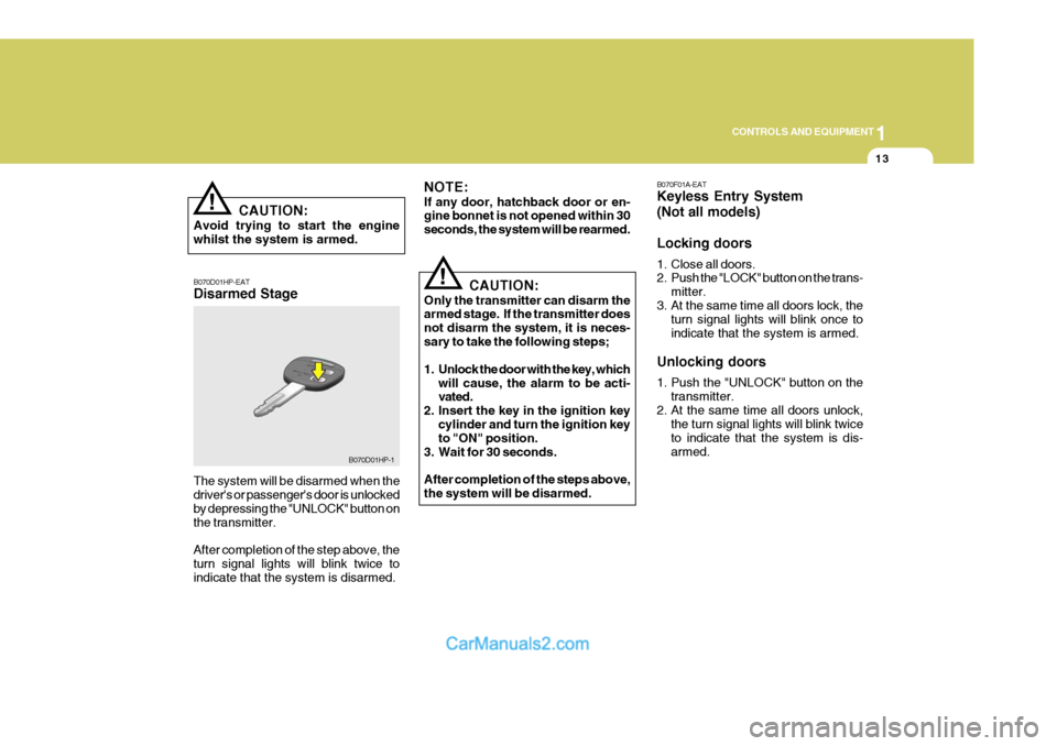
Avoid trying to start the engine whilst the system is armed. B070D01HP-EAT Disarmed Stage The system will be disarmed when the driver's or passenger's door is unlocked by depressing the "UNLOCK" button onthe transmitter. After completion of the step above, the turn signal lights will blink twice to indicate that the system is disarmed.
!
NOTE: If any door, hatchback door or en- gine bonnet is not opened within 30 seconds, the system will be rearmed.
CAUTION:
Only the transmitter can disarm the armed stage. If the transmitter does not disarm the system, it is neces-sary to take the following steps;
1. Unlock the door with the key, which will cause, the alarm to be acti- vated.
2. Insert the key in the ignition key
cylinder and turn the ignition keyto "ON" position.
3. Wait for 30 seconds. After completion of the steps above, the system will be disarmed.
B070D01HP-1 B070F01A-EAT Keyless Entry System (Not all models) Locking doors
1. Close all doors.
2. Push the "LOCK" button on the trans-
mitter.
3. At the same time all doors lock, the turn signal lights will blink once to indicate that the system is armed.
Unlocking doors
1. Push the "UNLOCK" button on the transmitter.
2. At the same time all doors unlock, the turn signal lights will blink twice to indicate that the system is dis-armed.
Page 357 of 539
1CONTROLS AND EQUIPMENT
52
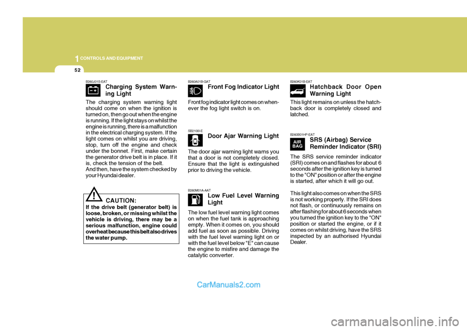
SB2100I-EDoor Ajar Warning Light
B260M01A-AAT Low Fuel Level Warning Light
B260A01B-GAT
Front Fog Indicator Light B260K01B-EAT
Hatchback Door OpenWarning Light
B260B01HP-EAT SRS (Airbag) ServiceReminder Indicator (SRI)
!
B260J01S-EAT
Charging System Warn- ing Light
CAUTION:
If the drive belt (generator belt) is loose, broken, or missing whilst thevehicle is driving, there may be a serious malfunction, engine could overheat because this belt also drivesthe water pump.
The charging system warning light should come on when the ignition is turned on, then go out when the engine is running. If the light stays on whilst theengine is running, there is a malfunction in the electrical charging system. If the light comes on whilst you are driving,stop, turn off the engine and check under the bonnet. First, make certain the generator drive belt is in place. If itis, check the tension of the belt. And then, have the system checked by your Hyundai dealer. Front fog indicator light comes on when-ever the fog light switch is on. The door ajar warning light warns you that a door is not completely closed. Ensure that the light is extinguished prior to driving the vehicle. The low fuel level warning light comes on when the fuel tank is approachingempty. When it comes on, you should add fuel as soon as possible. Driving with the fuel level warning light on orwith the fuel level below "E" can cause the engine to misfire and damage the catalytic converter. This light remains on unless the hatch-back door is completely closed and latched. The SRS service reminder indicator (SRI) comes on and flashes for about 6 seconds after the ignition key is turned to the "ON" position or after the engineis started, after which it will go out. This light also comes on when the SRS is not working properly. If the SRI does not flash, or continuously remains on after flashing for about 6 seconds whenyou turned the ignition key to the "ON" position or started the engine, or if it comes on whilst driving, have the SRSinspected by an authorised Hyundai Dealer.
Page 363 of 539
1CONTROLS AND EQUIPMENT
58
The needle on the coolant temperature gauge should stay in the normal range.If it moves across the dial to "H" (Hot), pull over and stop as soon as possible and turn off the engine. Then open thebonnet and check the coolant level and the water pump drive belt. If you sus- pect cooling system trouble, have yourcooling system checked by Hyundai dealer as soon as possible.
! CAUTION:
The engine should not be raced to such a speed that the needle enters the red zone on the tachometer face. This can cause severe engine dam-age and may void your warranty.
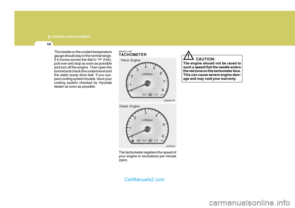
B330A01L-AAT TACHOMETER The tachometer registers the speed of your engine in revolutions per minute (rpm).Petrol Engine
B330A01HP
HHP2078
Diesel Engine
Page 388 of 539
1
CONTROLS AND EQUIPMENT
83
HHP2017-1
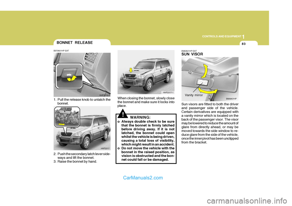
BONNET RELEASE
2. Push the secondary latch lever side-
ways and lift the bonnet.
3. Raise the bonnet by hand. B570A01HP-EAT
1. Pull the release knob to unlatch the
bonnet. HHP2016-E
HHP2017
!
When closing the bonnet, slowly close the bonnet and make sure it locks into place. WARNING:
o Always double check to be sure that the bonnet is firmly latched before driving away. If it is not latched, the bonnet could open whilst the vehicle is being driven,causing a total loss of visibility, which might result in an accident.
o Do not move the vehicle with the bonnet in the raised position, asvision is obstructed and the bon- net could fall or be damaged. B580A01HP-EAT SUN VISOR Sun visors are fitted to both the driver and passenger side of the vehicle. Certain derivatives are equipped with a vanity mirror which is located on theback of the passenger visor. The visor may be lowered to reduce the amount of glare from directly ahead, or may bemoved towards the side window to re- duce glare from the side of the vehicle, once the inner pivot has been unclippedfrom the bracket.B580A01HPVanity mirror
Page 448 of 539
3 IN CASE OF EMERGENCY
4
!
1. Ensure that the booster battery is 12
volt type. If the booster battery is installed in another vehicle, ensure that the two vehicles are not touch- ing.
2. Turn off all unnecessary electrical equipment in both vehicles.
3. Ensure that the engine of the ve- hicle providing the jump start is run- ning prior to connection of the jump cables.
4. Connect the red jump cable to the positive (+) terminal of the boosterbattery and the other end to thepositive (+) terminal of the dis- charged battery.
5. Attach the black jump cable to the negative (-) terminal of the boosterbattery, and the other end to a ground point within the engine compartmentof the vehicle with the flat bat-tery. Do not connect to the negative bat- tery terminal of the flat battery sincesparks may be generated with the subsequent risk of explosion.
6. Raise the booster vehicle engine speed to 2,000 r.p.m. and start theengine of the vehicle with the flat battery. 7. Switch "ON" the main beam
headlamps before carefully remov-ing the jumper cables in the reverse order of attachment. Once the jumper cables have been removed,switch "OFF" the main beam headlamps.
CAUTION:
If the jump cable is incorrectly in- stalled, damage to the vehicle elec- trical system may occur, in particu- lar the electronic components suchas the Fuel Injection system com- puter and the Automatic transmis- sion computer. The battery mustnever be disconnected whilst the engine is running.
IF THE ENGINE OVERHEATS
HPD040A2-E If the temperature gauge indicates overheating:
1. Pull off the road and stop as soon as it is safe to do so.
2. Place the gear selector lever in "P"
(automatic), or neutral (manual trans- mission) and set the parking brake. If the air conditioning is on, turn it off.
3. If coolant is running out under the car or steam is coming out from underthe bonnet, stop the engine. Do not open the bonnet until the coolant hasstopped running or the steaming has stopped. If there is no visible loss of coolant and no steam, leave theengine running and check to be sure the engine cooling fan is operating. If the fan is not running, turn theengine off.
4. Check to see if the water pump drive
belt is missing. If it is not missing,check to see that it is tight. If the drive belt seems to be satisfactory, check for coolant leaking from theradiator, hoses or under the car. (If the air conditioning had been in use, it is normal for cold water to bedraining from it).
Page 485 of 539
6 OWNER MAINTENANCE
8
!
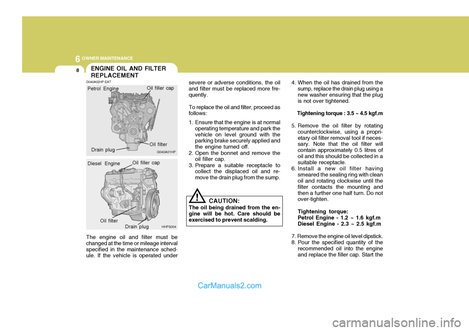
The engine oil and filter must be changed at the time or mileage intervalspecified in the maintenance sched- ule. If the vehicle is operated under severe or adverse conditions, the oil and filter must be replaced more fre-quently.
To replace the oil and filter, proceed as
follows:
1. Ensure that the engine is at normal
operating temperature and park the vehicle on level ground with the parking brake securely applied and the engine turned off.
2. Open the bonnet and remove the oil filler cap.
3. Prepare a suitable receptacle to collect the displaced oil and re-move the drain plug from the sump. 4. When the oil has drained from the
sump, replace the drain plug using anew washer ensuring that the plug is not over tightened.
Tightening torque : 3.5 ~ 4.5 kgf.m
5. Remove the oil filter by rotating counterclockwise, using a propri- etary oil filter removal tool if neces- sary. Note that the oil filter will contain approximately 0.5 litres ofoil and this should be collected in a suitable receptacle.
6. Install a new oil filter having smeared the sealing ring with cleanoil and rotating clockwise until the filter contacts the mounting andthen a further one half turn. Do not over-tighten. Tightening torque: Petrol Engine - 1.2 ~ 1.6 kgf.m Diesel Engine - 2.3 ~ 2.5 kgf.m
7. Remove the engine oil level dipstick.
8. Pour the specified quantity of the recommended oil into the engine and replace the filler cap. Start the
CAUTION:
The oil being drained from the en-
gine will be hot. Care should be exercised to prevent scalding.
ENGINE OIL AND FILTER REPLACEMENT
G040A02HP-EAT
G040A01HP
Petrol Engine
Oil filter
Drain plug Oil filler cap
HHP5004
Diesel Engine
Oil filler capOil filter
Drain plug
Page 495 of 539
6 OWNER MAINTENANCE
18
!
Transmission Fluid Capacity The fluid capacity of the automatic transmission is 10.5 litres (Petrol En- gine)/ 11.8 litres (Diesel Engine).
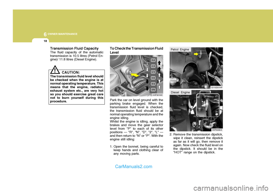
To Check the Transmission Fluid Level
2. Remove the transmission dipstick,wipe it clean, reinsert the dipstick as far as it will go, then remove it again. Now check the fluid level on the dipstick. It should be in the"HOT" range on the dipstick.
CAUTION:
The transmission fluid level shouldbe checked when the engine is atnormal operating temperature. This means that the engine, radiator, exhaust system etc., are very hotso you should exercise great care not to burn yourself during this procedure. Park the car on level ground with the
parking brake engaged. When thetransmission fluid level is checked, the transmission fluid should be at normal operating temperature and theengine idling.
Whilst the engine is idling, apply the
brakes and move the gear selectorlevel from "P" to each of its other positions — "R", "N", "D", "2", "L" — and then return to "N" or "P". With theengine still idling:
1. Open the bonnet, being careful to keep hands and clothing clear of any moving parts.
HHP3018-E
HHP5009-E
G110D01HP
Petrol Engine
Diesel Engine
Page 508 of 539
6
OWNER MAINTENANCE
31
!
!
3. Check to be sure that the warning
lamp illuminates when the ignition key is turned to "ON", and that it goes off when the engine is started. If in doubt, consult your nearest authorised HYUNDAI dealer.
NOTE: It is recommended that water accu- mulated in the fuel filter should be removed by an authorised Hyundai dealer.
WARNING:
Be sure to carefully wipe away anywater drained out in this manner, because the fuel mixed in the water might be ignited and resultin a fire. Before attempting to replace a head-
light bulb, be sure the switch is turned to the "OFF" position.
The next paragraph shows how to
reach the headlight bulbs so they may be changed. Be sure to replacethe burned-out bulb with one of the same number and wattage rating.
Ensure that the replacement bulb has
the same cap configuration and watt-age as the original.
See page 6-35 for the wattage descrip-
tions.
CAUTION:
Keep the lamps out of contact with
petroleum product, such as oil, petrol, etc.
REPLACING HEADLIGHT BULBS
G260A01HP-EAT
G270A01B-EAT Headlight Bulb
1. Allow the bulb to cool. Wear eye
protection.
2. Open the engine bonnet.
3. Always grasp the bulb by its plas- tic base, avoid touching the glass.
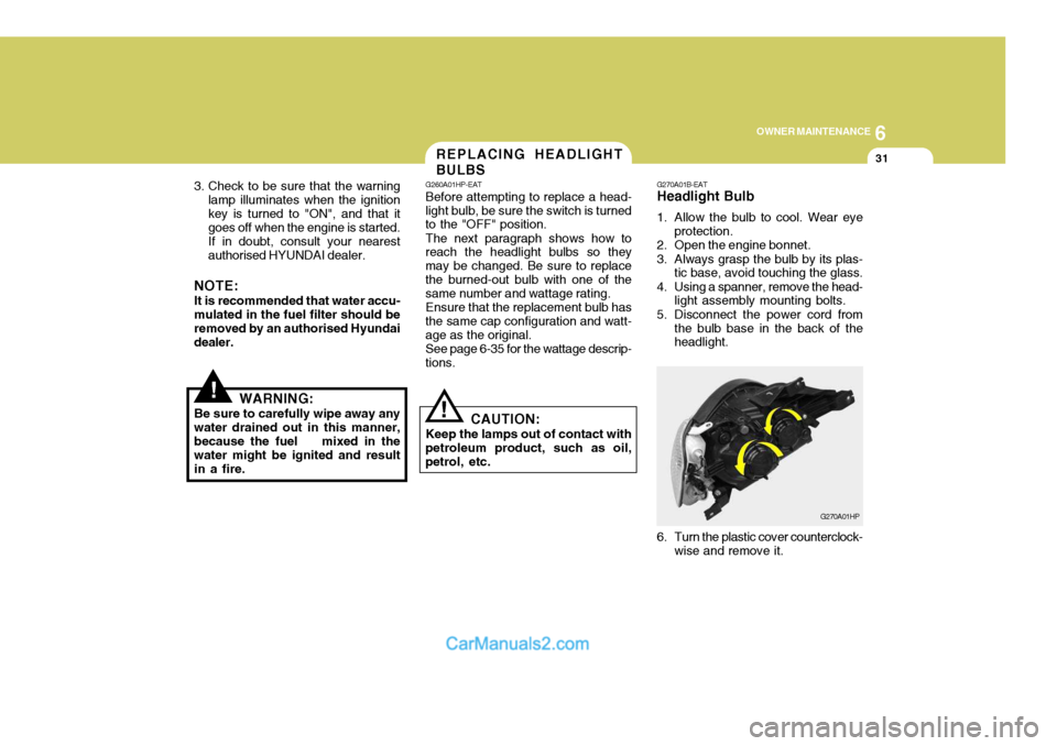
4. Using a spanner, remove the head- light assembly mounting bolts.
5. Disconnect the power cord from the bulb base in the back of the headlight.
G270A01HP
6. Turn the plastic cover counterclock- wise and remove it.
Page 510 of 539
6
OWNER MAINTENANCE
33
And then, draw a parallel line at 1.50 in. (38 mm) under the horizontal line incase of adjusting the low beam or at 0.83 in. (21 mm) under the horizontal line in case of adjusting the high beam.
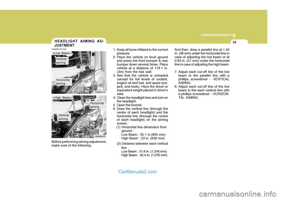
7. Adjust each cut-off line of the low beam to the parallel line with a phillips screwdriver - VERTICAL AIMING.
8. Adjust each cut-off line of the low beam to the each vertical line witha phillips screwdriver - HORIZON-TAL AIMING.
Before performing aiming adjustment,make sure of the following.HEADLIGHT AIMING AD- JUSTMENT
G290A01HP-EAT
1. Keep all tyres inflated to the correct
pressure.
2. Place the vehicle on level ground and press the front bumper & rear bumper down several times. Placevehicle at a distance of 118.1 in. (3m) from the test wall.
3. See that the vehicle is unloaded (except for full levels of coolant, engine oil and fuel, and spare tyre,jack, and tools). Have the driver or equivalent weight placed in driver's seat.
4. Clean the headlight lens and turn on the headlight.
5. Open the bonnet.
6. Draw the vertical line (through the centre of each headlight) and thehorizontal line (through the centre of each headlight) on the aiming screen.
(1) Horizontal line dimension from
Horizontal aiming
Vertical aiming
G290B01HP
G290B02HP
Horizontal aiming
Vertical aiming
ground : Low Beam : 35.1 in.(894 mm) High Beam : 33 in. (839 mm)
(2) Distance between each vertical line :Low Beam : 51.8 in. (1,316 mm) High Beam : 42.4 in. (1,076 mm)