steering wheel Hyundai Terracan 2005 Owner's Manual
[x] Cancel search | Manufacturer: HYUNDAI, Model Year: 2005, Model line: Terracan, Model: Hyundai Terracan 2005Pages: 539, PDF Size: 18.03 MB
Page 11 of 539
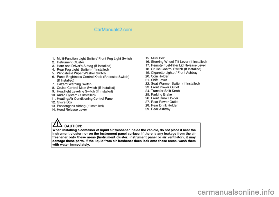
1. Multi-Function Light Switch/ Front Fog Light Switch
2. Instrument Cluster
3. Horn and Driver's Airbag (If Installed)
4. Rear Fog Light Switch (If Installed)
5. Windshield Wiper/Washer Switch
6. Panel Brightness Control Knob (Rheostat Switch)(If Installed)
7. Hazard Warning Switch
8. Cruise Control Main Switch (If Installed)
9. Headlight Leveling Switch (If Installed)
10. Audio System (If Installed)
11. Heating/Air Conditioning Control Panel
12. Glove Box
13. Passenger's Airbag (If Installed)
14. Hood Release Lever
CAUTION:
When installing a container of liquid air freshener inside the vehicle, do not place it near theinstrument cluster nor on the instrument panel surface. If there is any leakage from the air freshener onto these areas (Instrument cluster, instrument panel or air ventilator), it maydamage these parts. If the liquid from air freshener does leak onto these areas, wash them with water immediately.
! 15. Multi Box
16. Steering Wheel Tilt Lever (If Installed)
17. Remote Fuel-Filler Lid Release Lever
18. Cruise Control Switch (If Installed)
19. Cigarette Lighter/ Front Ashtray
20. Coin Holder
21. Shift Lever
22. Seat Warmer Switch (If Installed)
23. Front Power Outlet
24. Transfer Shift Knob
25. Parking Brake
26. Front Drink Holder
27. Rear Power Outlet
28. Rear Drink Holder
29. Rear Ashtray
Page 13 of 539
CAUTION:
When installing a container of liquid air freshener inside the vehicle, do not place it near the instrument cluster nor on the instrument panel surface. If there is any leakage from the air freshener onto these areas (Instrument cluster, instrument panel or air ventilator), it may damage these parts. If the liquid from air freshener does leak onto these areas, wash themwith water immediately.!
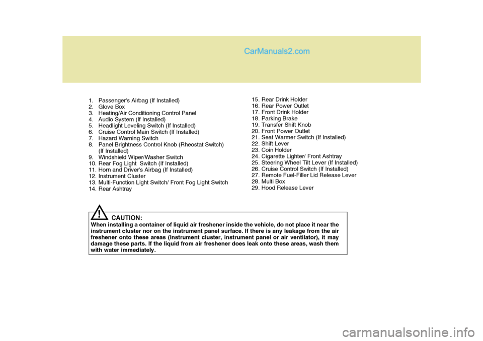
1. Passenger's Airbag (If Installed)
2. Glove Box
3. Heating/Air Conditioning Control Panel
4. Audio System (If Installed)
5. Headlight Leveling Switch (If Installed)
6. Cruise Control Main Switch (If Installed)
7. Hazard Warning Switch
8. Panel Brightness Control Knob (Rheostat Switch)
(If Installed)
9. Windshield Wiper/Washer Switch
10. Rear Fog Light Switch (If Installed)
11. Horn and Driver's Airbag (If Installed)
12. Instrument Cluster
13. Multi-Function Light Switch/ Front Fog Light Switch
14. Rear Ashtray 15. Rear Drink Holder
16. Rear Power Outlet
17. Front Drink Holder
18. Parking Brake
19. Transfer Shift Knob
20. Front Power Outlet
21. Seat Warmer Switch (If Installed)
22. Shift Lever
23. Coin Holder
24. Cigarette Lighter/ Front Ashtray
25. Steering Wheel Tilt Lever (If Installed)
26. Cruise Control Switch (If Installed)
27. Remote Fuel-Filler Lid Release Lever
28. Multi Box
29. Hood Release Lever
Page 35 of 539
1
FEATURES OF YOUR HYUNDAI
21
!
!
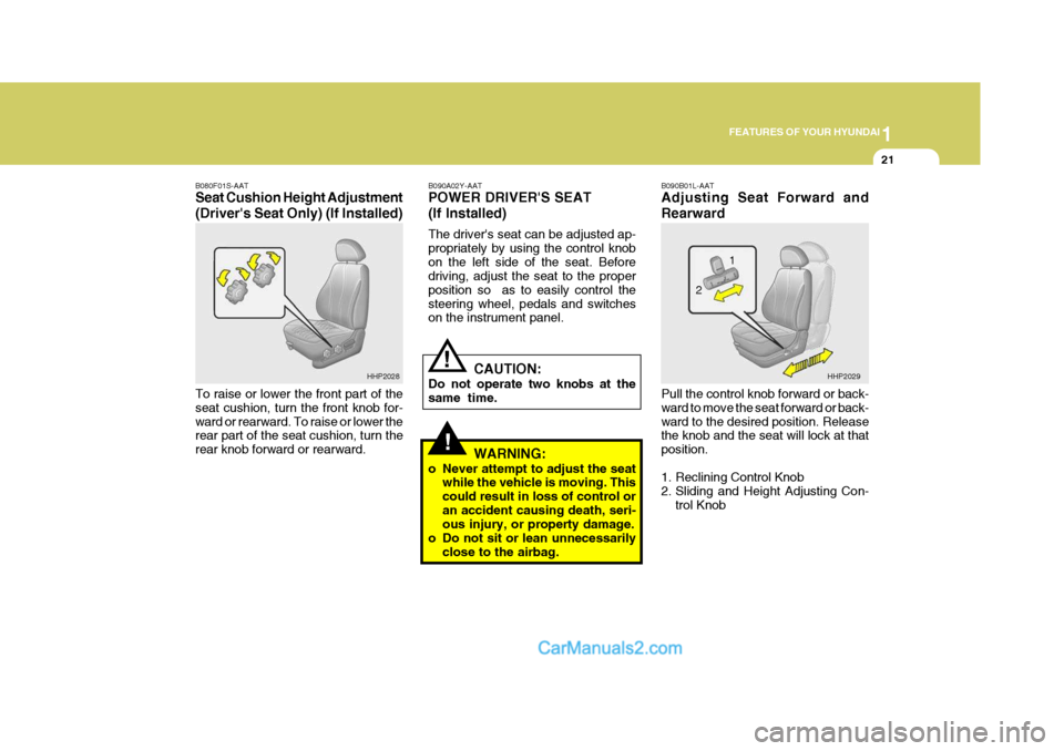
B090A02Y-AAT POWER DRIVER'S SEAT (If Installed) The driver's seat can be adjusted ap- propriately by using the control knobon the left side of the seat. Before driving, adjust the seat to the proper position so as to easily control thesteering wheel, pedals and switches on the instrument panel.
CAUTION:
Do not operate two knobs at the same time.
WARNING:
o Never attempt to adjust the seat while the vehicle is moving. Thiscould result in loss of control oran accident causing death, seri- ous injury, or property damage.
o Do not sit or lean unnecessarily close to the airbag. B090B01L-AAT Adjusting Seat Forward and Rearward Pull the control knob forward or back- ward to move the seat forward or back-ward to the desired position. Release the knob and the seat will lock at that position.
1. Reclining Control Knob
2. Sliding and Height Adjusting Con-
trol Knob
B080F01S-AAT Seat Cushion Height Adjustment (Driver's Seat Only) (If Installed) To raise or lower the front part of the seat cushion, turn the front knob for-ward or rearward. To raise or lower the rear part of the seat cushion, turn the rear knob forward or rearward.
HHP2028
HHP2029
1
2
Page 62 of 539
1FEATURES OF YOUR HYUNDAI
48
!
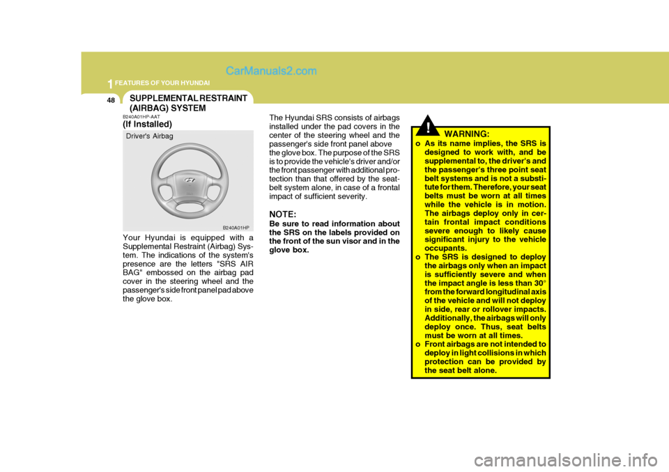
The Hyundai SRS consists of airbags installed under the pad covers in thecenter of the steering wheel and the passenger's side front panel above the glove box. The purpose of the SRSis to provide the vehicle's driver and/or the front passenger with additional pro- tection than that offered by the seat-belt system alone, in case of a frontal impact of sufficient severity. NOTE: Be sure to read information about the SRS on the labels provided on the front of the sun visor and in the glove box. WARNING:
o As its name implies, the SRS is designed to work with, and be supplemental to, the driver's and the passenger's three point seatbelt systems and is not a substi- tute for them. Therefore, your seat belts must be worn at all timeswhile the vehicle is in motion. The airbags deploy only in cer- tain frontal impact conditionssevere enough to likely cause significant injury to the vehicle occupants.
o The SRS is designed to deploy the airbags only when an impactis sufficiently severe and whenthe impact angle is less than 30° from the forward longitudinal axis of the vehicle and will not deployin side, rear or rollover impacts. Additionally, the airbags will only deploy once. Thus, seat beltsmust be worn at all times.
o Front airbags are not intended to
deploy in light collisions in whichprotection can be provided by the seat belt alone.
SUPPLEMENTAL RESTRAINT (AIRBAG) SYSTEM
B240A01HP-AAT (If Installed)
Your Hyundai is equipped with a Supplemental Restraint (Airbag) Sys- tem. The indications of the system'spresence are the letters "SRS AIR BAG" embossed on the airbag pad cover in the steering wheel and thepassenger's side front panel pad above the glove box. Driver's Airbag
B240A01HP
Page 63 of 539
1
FEATURES OF YOUR HYUNDAI
49
o No objects should be placed over
or near the airbag modules on the steering wheel, instrument panel, and the front passenger'spanel above the glove box, because any such object could cause harm if the vehicle is in acrash severe enough to cause the airbags to deploy.
o If the airbags deploy, they must be replaced by an authorizedHyundai dealer.
o Do not tamper with or discon- nect SRS wiring, or other com-ponents of the SRS system. Do- ing so could result in injury, dueto accidental firing of the airbags or by rendering the SRS inopera- tive.
o Do not install a child restraint system in the front passengerseat position. A child restraintsystem must never be placed in the front seat. The infant or child could be severely injured or killedby an airbag deployment in case of an accident. Do not allow chil- dren to ride in the front passen- ger seat. If older children (teen- agers and older) must ride in the front seat, make sure they arealways properly belted and that the seat is moved back as far as possible.
o For maximum safety protection in all types of crashes, all occu-pants including the driver shouldalways wear their seat belts whether or not an airbag is also provided at their seating posi-tion to minimize the risk of se- vere injury or death in the event of a crash. Do not sit or leanunnecessarily close to the airbag while the vehicle is in motion.
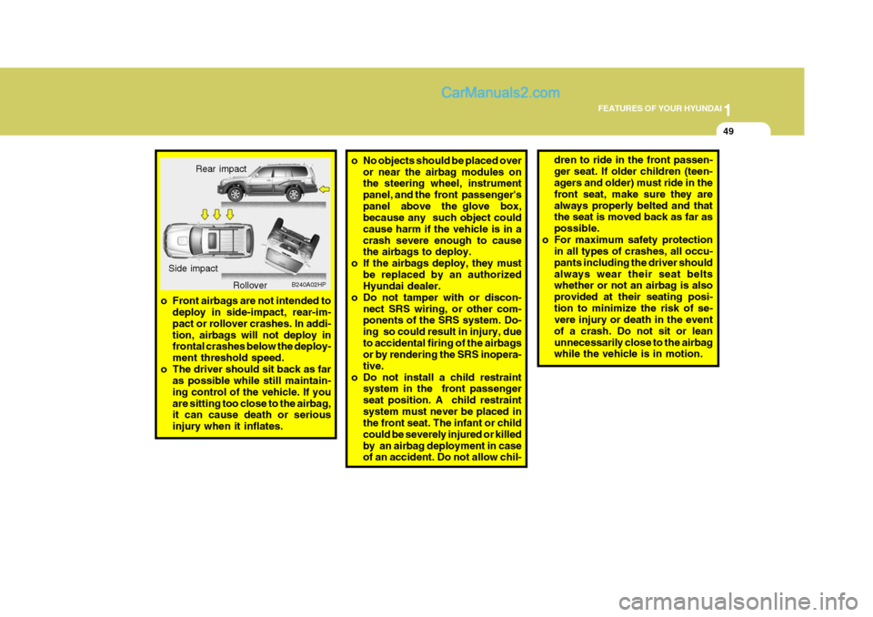
o Front airbags are not intended to
deploy in side-impact, rear-im- pact or rollover crashes. In addi-tion, airbags will not deploy in frontal crashes below the deploy- ment threshold speed.
o The driver should sit back as far as possible while still maintain-ing control of the vehicle. If youare sitting too close to the airbag, it can cause death or serious injury when it inflates. Rear impact
B240A02HP
Side impact
Rollover
Page 64 of 539
1FEATURES OF YOUR HYUNDAI
50
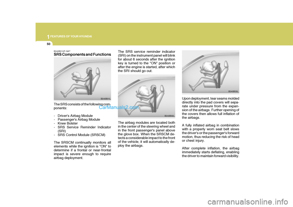
The SRS service reminder indicator (SRI) on the instrument panel will blinkfor about 6 seconds after the ignition key is turned to the "ON" position or after the engine is started, after whichthe SRI should go out.
Upon deployment, tear seams moldeddirectly into the pad covers will sepa- rate under pressure from the expan- sion of the airbags. Further opening ofthe covers then allows full inflation of the airbags. A fully inflated airbag in combination with a properly worn seat belt slows the driver's or the passenger's forwardmotion, thus reducing the risk of head or chest injury. After complete inflation, the airbag immediately starts deflating, enabling the driver to maintain forward visibility.
The airbag modules are located both in the center of the steering wheel and in the front passenger's panel abovethe glove box. When the SRSCM de- tects a considerable impact to the front of the vehicle, it will automatically de-ploy the airbags.
B240B02L
B240B03L
B240B01HP-GAT SRS Components and Functions The SRS consists of the following com- ponents:
- Driver's Airbag Module
- Passenger's Airbag Module
- Knee Bolster
- SRS Service Reminder Indicator
(SRI)
- SRS Control Module (SRSCM) The SRSCM continually monitors all elements while the ignition is "ON" todetermine if a frontal or near-frontal impact is severe enough to require airbag deployment. B240B01L
Page 66 of 539
1FEATURES OF YOUR HYUNDAI
52
o For cleaning the airbag pad cov-
ers, use only a soft, dry cloth or one which has been moistened with plain water. Solvents orcleaners could adversely affect the airbag covers and proper deployment of the system.
o No objects should be placed over or near the airbag modules onthe steering wheel, instrumentpanel, and the front passenger's panel above the glove box, be- cause any such object couldcause harm if the vehicle is in a crash severe enough to cause the airbags to inflate.
o If the airbags inflate, they must be replaced by an authorizedHyundai dealer.
o Do not tamper with or discon- nect SRS wiring, or other com-ponents of the SRS system. Do-ing so could result in injury, due to accidental firing of the airbags or by rendering the SRS inopera-tive.
!WARNING:
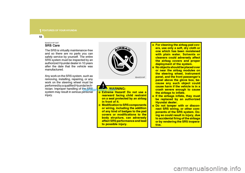
o Extreme Hazard! Do not use a rearward facing child restraint on a seat protected by an airbag in front of it.
o Modification to SRS components or wiring, including the additionof any kind of badges to the padcovers or modifications to the body structure, can adversely affect SRS performance and leadto possible injury. B240C01HP
B240C01HP-GAT SRS Care The SRS is virtually maintenance-free and so there are no parts you cansafely service by yourself. The entire SRS system must be inspected by an authorized Hyundai dealer in 10 yearsafter the date that the vehicle was manufactured. Any work on the SRS system, such as removing, installing, repairing, or any work on the steering wheel must beperformed by a qualified Hyundai tech- nician. Improper handling of the SRS system may result in serious personalinjury.
Page 75 of 539
1
FEATURES OF YOUR HYUNDAI
61
B260B01B-GAT Tail Gate Open Warning Light
This light remains on unless the tail gate is completely closed and latched. B260B01HP-GAT SRS (Airbag) Service Reminder Indicator (SRI)(If Installed)
The SRS service reminder indicator (SRI) comes on and flashes for about 6 seconds after the ignition key is turned to the "ON" position or after the engine is started, after which it will goout. This light also comes on when the SRS is not working properly. If the SRI does not flash, or continuously remains on after flashing for about 6 seconds whenyou turned the ignition key to the "ON" position or started the engine, or if it comes on while driving, have the SRSinspected by an authorized Hyundai Dealer.
B260N02A-AAT Malfunction Indicator Light (If Installed)
This light illuminates when there is a malfunction of an exhaust gas relatedcomponent, and the system is not functioning properly so that the ex- haust gas regulation values are notsatisfied. This light will also illuminate when the ignition key is turned to the "ON" position, and then it will go out ina few seconds after the engine is started. If it illuminates while driving, or does not illuminate when the ignitionkey is turned to the "ON" position, take your car to your nearest authorized Hyundai dealer and have the systemchecked.
B260E01HP-GAT Seat Belt Warning Light
The seat belt warning light blinks for about 6 seconds when the ignition key is turned from the "OFF" position to"ON" or "START".
B260Q01HP-DAT Cruise Indicator Light (For Gasoline Engine)(If Installed)
The cruise indicator light in the instru- ment cluster is illuminated only when the vehicle cruising speed has beenset using the control switch on the steering wheel. The indicator light does not illuminatewhen the main cruise control switch is activated. Information about the use of cruise control may be found on page 1-100.
B265Q01HP-GAT Cruise Indicator Light (For Diesel Engine)(If Installed)
The cruise indicator light in the instru- ment cluster is illuminated when the cruise control main switch is activated.Information about the use of cruise control may be found on page 1-100.
Page 112 of 539
1FEATURES OF YOUR HYUNDAI
98
!WARNING:
Do not place the sun visor in such a manner that it obscures visibility of the roadway, traffic or other ob- jects.
HORNFRONT DOOR EDGE WARNING LIGHT
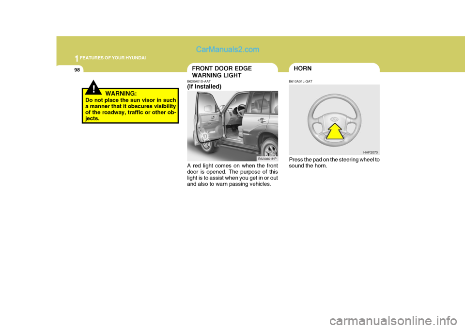
B620A01S-AAT (If Installed) A red light comes on when the front door is opened. The purpose of this light is to assist when you get in or outand also to warn passing vehicles. B610A01L-GAT Press the pad on the steering wheel to sound the horn.
B620A01HP
HHP2070
Page 113 of 539
1
FEATURES OF YOUR HYUNDAI
99HEADLIGHT LEVELING DE- VICE SYSTEMSTEERING WHEEL TILT LEVERREAR SEAT ARMREST
!
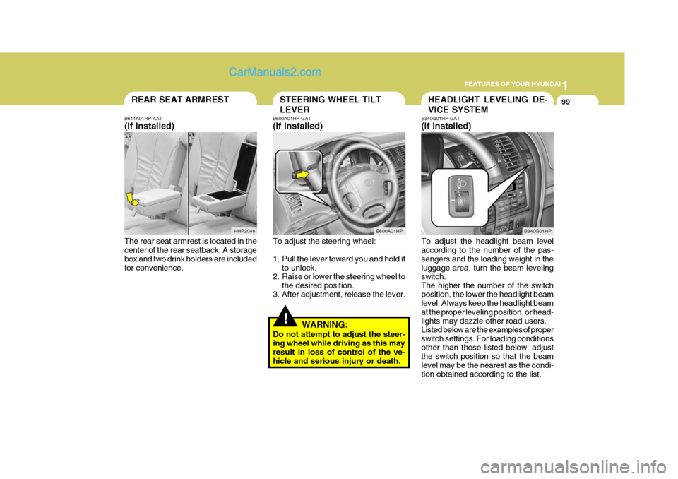
B611A01HP-AAT (If Installed) The rear seat armrest is located in the center of the rear seatback. A storage box and two drink holders are includedfor convenience. B600A01HP-GAT (If Installed) To adjust the steering wheel:
1. Pull the lever toward you and hold it
to unlock.
2. Raise or lower the steering wheel to
the desired position.
3. After adjustment, release the lever.
WARNING:
Do not attempt to adjust the steer- ing wheel while driving as this may result in loss of control of the ve- hicle and serious injury or death. B340G01HP-GAT (If Installed) To adjust the headlight beam level according to the number of the pas- sengers and the loading weight in theluggage area, turn the beam leveling switch. The higher the number of the switchposition, the lower the headlight beam level. Always keep the headlight beam at the proper leveling position, or head-lights may dazzle other road users. Listed below are the examples of proper switch settings. For loading conditionsother than those listed below, adjust the switch position so that the beam level may be the nearest as the condi-tion obtained according to the list.
B600A01HP
B340G01HP
HHP2048