Hyundai Tiburon 2005 Owner's Manual
Manufacturer: HYUNDAI, Model Year: 2005, Model line: Tiburon, Model: Hyundai Tiburon 2005Pages: 262, PDF Size: 11.12 MB
Page 231 of 262
6
DO-IT-YOURSELF MAINTENANCE
42
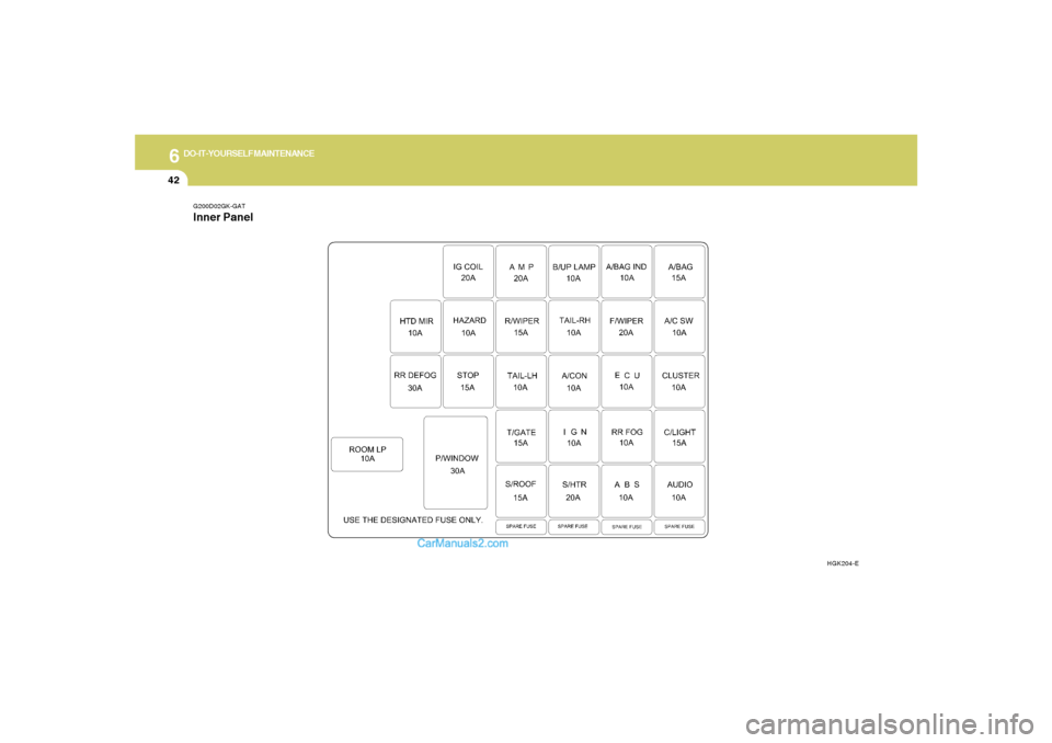
G200D02GK-GATInner Panel
HGK204-E
Page 232 of 262
6
DO-IT-YOURSELF MAINTENANCE
43
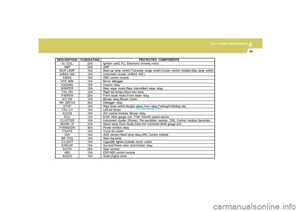
DESCRIPTION
IG COIL
AMP
B/UP LAMP
A/BAG IND
A/BAG
HTD MIR
HAZARD
R/WIPER
TAIL-RH
F/WIPER
A/C SW
RR DEFOG
STOP
TAIL-LH
A/CON
ECU
CLUSTER
ROOM LP
P/WINDOW
T/GATE
IGN
RR FOG
C/LIGHT
S/ROOF
S/HTR
ABS
AUDIO
PROTECTED COMPONENTS
Ignition coil(2.7L), Electronic chrome mirror
AMP
Back-up lamp switch,Transaxle range switch,Cruise control module,Stop lamp switch
Instrument cluster (A/BAG IND.)
SRS control module
Mirror defogger
Hazard relay
Rear wiper motor,Rear intermittent wiper relay
Right tail lamps,Glove box lamp
Front wiper motor,Front wiper relay
Blower relay,Blower motor
Defogger relay
Stop lamp switch,Burglar alarm horn relay,Folding/Unfolding rely
Left tail lamps
A/C control module, Blower relay
ECM, Multi gauge unit, TCM, Vehicle speed sensor
Instrument cluster (Power), Per-excitation resister, DRL Control module,Generator
Room lamp,Clock,Audio,Data link connector,Multi gauge unit
Power window relay
Trunk lid switch
AQS sensor,Head lamp relay,DRL Control module
Rear fog lamp
Cigarette lighter,Outside mirror switch
Sunroof,Power door lock/Unlock relay
Seat warmer
ESP/ABS control module
Audio,Digital clock FUSERATING
20A
20A
10A
10A
15A
10A
10A
15A
10A
20A
10A
30A
15A
10A
10A
10A
10A
10A
30A
15A
10A
10A
15A
15A
20A
10A
10A
Page 233 of 262
EMISSION CONTROL SYSTEMS
7
Emission Control System ............................................. 7-2
Catalytic Converter ....................................................... 7-3
7
Page 234 of 262
7
EMISSION CONTROL SYSTEMS2
EMISSION CONTROL SYSTEM
H010D01A-AAT3. Exhaust Emission Control SystemThe Exhaust Emission Control System is a
highly effective system which controls exhaust
emissions while maintaining good vehicle per-
formance.
H010B01A-AAT1. Crankcase Emission Control
SystemThe Positive Crankcase Ventilation System is
employed to prevent air pollution caused by
blow-by gases being emitted from the crank-
case. This system supplies fresh filtered air to
the crankcase through the air intake hose.
Inside the crankcase, the fresh air mixes with
blow-by gases, which then pass through the
PCV valve and into the induction system.
H010A02GK-AATYour Hyundai is equipped with an emission
control system to meet all requirements of the
U.S. Environmental Protection Agency or Cali-
fornia Air Resources Board.
There are three emission control systems which
are as follows.
1) Crankcase Emission Control System
2) Evaporative Emission Control System
3) Exhaust Emission Control System
In order to ensure the proper function of the
emission control systems, it is recommended
that you have your car inspected and main-
tained by an authorized Hyundai dealer in ac-
cordance with the maintenance schedule in this
manual.
Caution for the Inspection and Maintenance
Test (Vehicle with Electronic Stability Pro-
gram)
o To prevent the vehicle from misfiring
during dynamometer testing, discon-
nect the ABS connector located inside
of the wheel guard (driver side).
o For more information, see shop manual
(BR Group, Wheel Speed Sensor).
CanisterFuel vapors generated inside the fuel tank are
absorbed and stored in the onboard canister.
When the engine is running, the fuel vapors
absorbed in the canister are drawn into the
induction system through the purge control
solenoid valve.Purge Control Solenoid Valve (PCSV)The purge control solenoid valve is controlled
by the Engine Control Module (ECM); when the
engine coolant temperature is low during idling,
the PCSV closes so that evaporated fuel is not
taken into the engine. After the engine warms-
up during ordinary driving, the PCSV opens to
introduce evaporated fuel to the engine.
H010C01S-AAT2. Evaporative Emission Control (Includ-
ing ORVR: Onboard Refueling Vapor
Recovery) SystemThe Evaporative Emission Control System is
designed to prevent fuel vapors from escaping
into the atmosphere.
(The ORVR system is designed to allow the
vapors from the fuel tank to be loaded into a
canister while refueling at the gas station, pre-
venting the escape of fuel vapors into the
atmosphere.)
Page 235 of 262
7
EMISSION CONTROL SYSTEMS
3
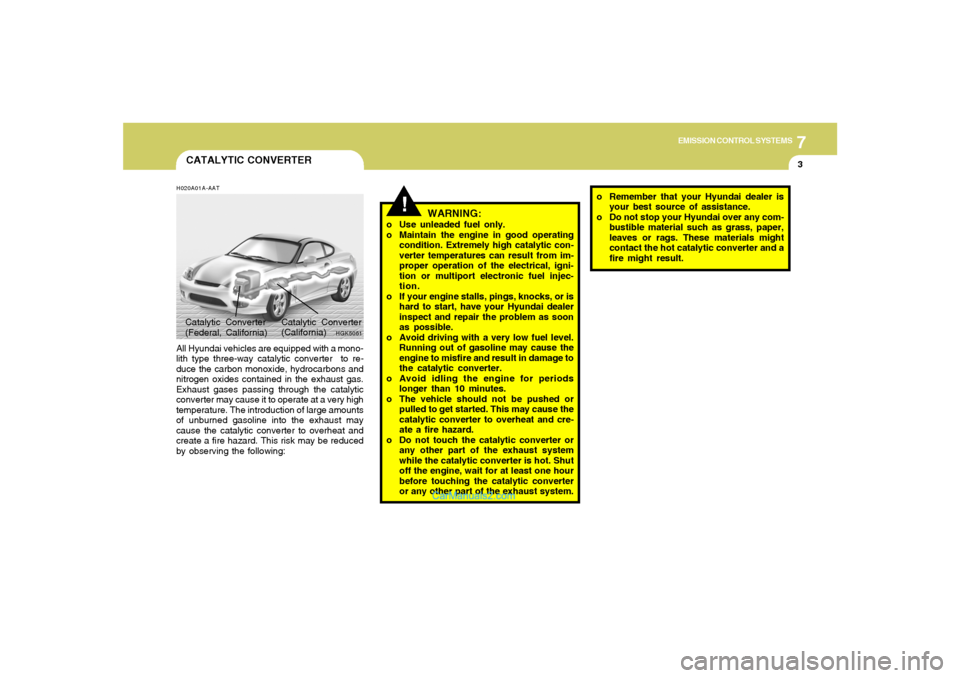
CATALYTIC CONVERTERH020A01A-AATAll Hyundai vehicles are equipped with a mono-
lith type three-way catalytic converter to re-
duce the carbon monoxide, hydrocarbons and
nitrogen oxides contained in the exhaust gas.
Exhaust gases passing through the catalytic
converter may cause it to operate at a very high
temperature. The introduction of large amounts
of unburned gasoline into the exhaust may
cause the catalytic converter to overheat and
create a fire hazard. This risk may be reduced
by observing the following:
HGK5061
Catalytic Converter
(California) Catalytic Converter
(Federal, California)
!
WARNING:
o Use unleaded fuel only.
o Maintain the engine in good operating
condition. Extremely high catalytic con-
verter temperatures can result from im-
proper operation of the electrical, igni-
tion or multiport electronic fuel injec-
tion.
o If your engine stalls, pings, knocks, or is
hard to start, have your Hyundai dealer
inspect and repair the problem as soon
as possible.
o Avoid driving with a very low fuel level.
Running out of gasoline may cause the
engine to misfire and result in damage to
the catalytic converter.
o Avoid idling the engine for periods
longer than 10 minutes.
o The vehicle should not be pushed or
pulled to get started. This may cause the
catalytic converter to overheat and cre-
ate a fire hazard.
o Do not touch the catalytic converter or
any other part of the exhaust system
while the catalytic converter is hot. Shut
off the engine, wait for at least one hour
before touching the catalytic converter
or any other part of the exhaust system.o Remember that your Hyundai dealer is
your best source of assistance.
o Do not stop your Hyundai over any com-
bustible material such as grass, paper,
leaves or rags. These materials might
contact the hot catalytic converter and a
fire might result.
Page 236 of 262
Vehicle Identification Number (VIN) .............................. 8-2
Engine Number ............................................................. 8-2
Recommended Inflation Pressures ............................... 8-3
Tire Sidewall Labeling ................................................... 8-4
Tire Terminology and Definitions ................................... 8-6
Snow Tires .................................................................... 8-8
Tire Chains .................................................................... 8-9
Tire Rotation .................................................................. 8-9
Tire Balancing.............................................................8-10
Tire Traction................................................................8-10
When to Replace Tires ...............................................8-10
Spare Tire and Tools ...................................................8-11
Warranties for Your Hyundai Vehicle..........................8-11
Consumer Information.................................................8-11
Reporting Safety Defects............................................8-13
Binding Arbitration of Warranty Claims.......................8-15
CONSUMER INFORMATION, REPORTING
SAFETY DEFECTS & BINDING
ARBITRATION OF WARRANTY CLAIMS
8
8
Page 237 of 262
8
CONSUMER INFORMATION, REPORTING SAFETY DEFECTS & BINDING ARBITRATION OF WARRANTY CLAIMS2
ENGINE NUMBER
VEHICLE IDENTIFICATION
NUMBER (VIN)
I010B01A-AAT I010A01A-AAT
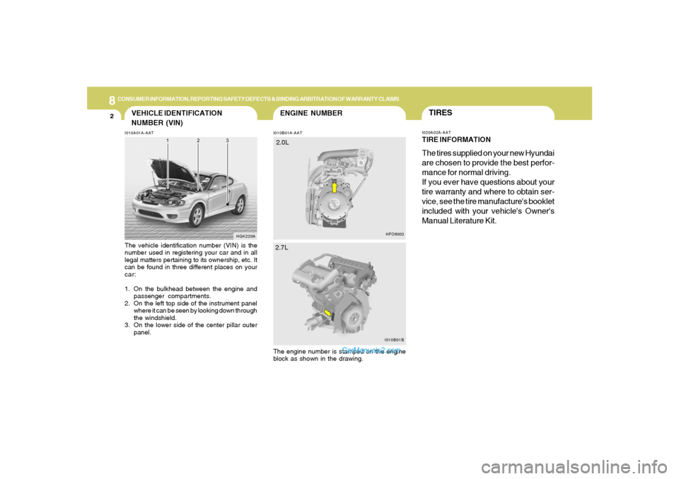
The vehicle identification number (VIN) is the
number used in registering your car and in all
legal matters pertaining to its ownership, etc. It
can be found in three different places on your
car:
1. On the bulkhead between the engine and
passenger compartments.
2. On the left top side of the instrument panel
where it can be seen by looking down through
the windshield.
3. On the lower side of the center pillar outer
panel.
The engine number is stamped on the engine
block as shown in the drawing.
HGK220A
TIRESI020A02A-AATTIRE INFORMATIONThe tires supplied on your new Hyundai
are chosen to provide the best perfor-
mance for normal driving.
If you ever have questions about your
tire warranty and where to obtain ser-
vice, see the tire manufacture's booklet
included with your vehicle's Owner's
Manual Literature Kit.
I010B01B
2.7L
HFO6003
2.0L
Page 238 of 262
8
CONSUMER INFORMATION, REPORTING SAFETY DEFECTS & BINDING ARBITRATION OF WARRANTY CLAIMS
3
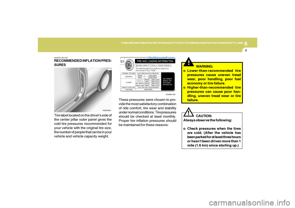
I030A01JM-AATRECOMMENDED INFLATION PRES-
SURES
Tire label located on the driver's side of
the center pillar outer panel gives the
cold tire pressures recommended for
your vehicle with the original tire size,
the number of people that can be in your
vehicle and vehicle capacity weight.These pressures were chosen to pro-
vide the most satisfactory combination
of ride comfort, tire wear and stability
under normal conditions. Tire pressures
should be checked at least monthly.
Proper tire inflation pressures should
be maintained for these reasons:
I030B01GK
HGK6003
!
CAUTION:
Always observe the following:
o Check pressures when the tires
are cold. (After the vehicle has
been parked for at least three hours
or hasn't been driven more than 1
mile (1.6 km) since starting up.)
!
WARNING:
o Lower-than-recommended tire
pressures cause uneven tread
wear, poor handling, poor fuel
economy or tire failure.
o Higher-than-recommended tire
pressures can cause poor han-
dling, uneven tread wear or tire
failure.
Page 239 of 262
8
CONSUMER INFORMATION, REPORTING SAFETY DEFECTS & BINDING ARBITRATION OF WARRANTY CLAIMS4
Check the tire's inflation pressure when
the tires are cold. - "Cold" means your
vehicle has been sitting for at least
three hours or driven no more than 1
mile (1.6 km).
Remove the valve cap from the tire
valve stem. Press the tire gage firmly
onto the valve to get a pressure mea-
surement. If the cold tire inflation pres-
sure matches the recommended pres-
sure on the tire and loading information
label, no further adjustment is neces-
sary. If the pressure is low, add air until
you reach the recommended amount.
If you overfill the tire, release air by
pushing on the metal stem in the center
of the tire valve. Recheck the tire pres-
sure with the tire gage. Be sure to put
the valve caps back on the valve stems.
They help prevent leaks by keeping out
dirt and moisture.
I035A01JM-AATCHECKING TIRE INFLATION PRES-
SURE
Check your tires once a month or more.
Also, check the tire pressure of the
spare tire.
How to Check
Use a good quality gage to check tire
pressure. You can not tell if your tires
are properly inflated simply by looking
at them. Radial tires may look properly
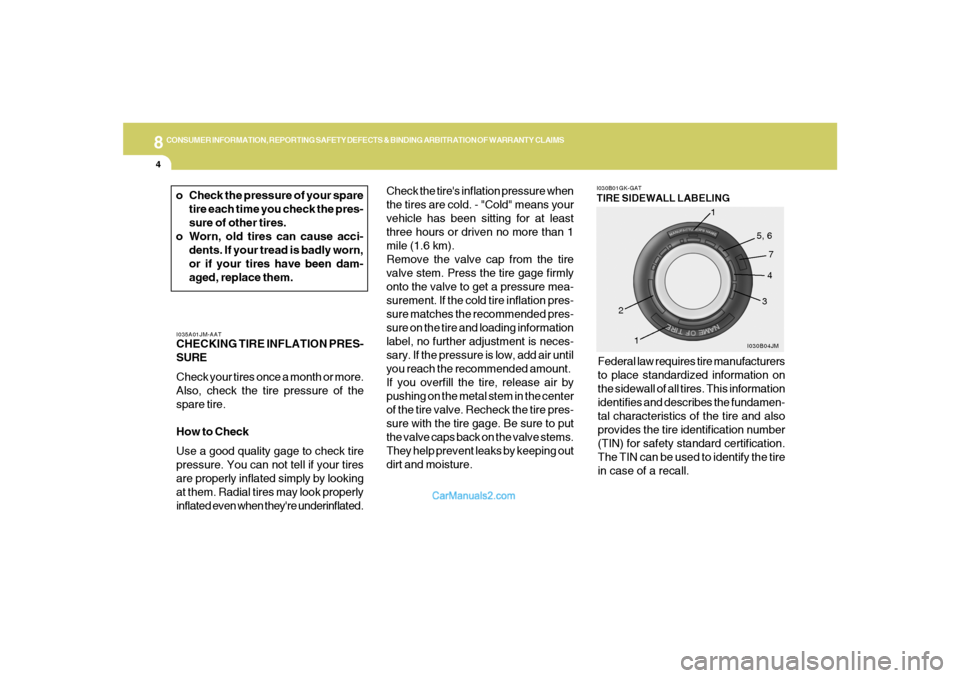
inflated even when they're underinflated.Federal law requires tire manufacturers
to place standardized information on
the sidewall of all tires. This information
identifies and describes the fundamen-
tal characteristics of the tire and also
provides the tire identification number
(TIN) for safety standard certification.
The TIN can be used to identify the tire
in case of a recall.
I030B01GK-GATTIRE SIDEWALL LABELING
I030B04JM
1
234 5, 6
7
1
o Check the pressure of your spare
tire each time you check the pres-
sure of other tires.
o Worn, old tires can cause acci-
dents. If your tread is badly worn,
or if your tires have been dam-
aged, replace them.
Page 240 of 262
8
CONSUMER INFORMATION, REPORTING SAFETY DEFECTS & BINDING ARBITRATION OF WARRANTY CLAIMS
5
1. Manufacturer or Brand name
o Manufacturer or Brand name is
shown.
2. Tire size
(example: P215/45R17 87V)
o The "P" indicates the tire is de-
signed for passenger vehicles.
A "T" is the designation for a tem-
porary spare tire.
o Three-digit number (215): This num-
ber gives the width in millimeters
of the tire from sidewall edge to
sidewall edge.
o Two-digit number (45): This num-
ber, known as the aspect ratio,
gives the tire's ratio of height to
width.
o R: The "R" stands for radial.
o Two-digit number (17): This num-
ber is the wheel or rim diameter in
inches.
o Two digit number (87): This num-
ber is the tire's load index. It is a
measurement of how much weight
each tire can support.o V: Speed Rating. The speed rating
denotes the speed at which a tire is
designed to be driven for extended
periods of time. The ratings range
from "A" to "Z" (98 to 186 MPH).
3. TIN (Tire Identification Number) for
new tire (example: DOT XX XX XXX
XXXX)
o DOT: Abbreviation for the "Depart-
ment of Transportation". The sym-
bol can be placed above, below or
to the left or right of the Tire Iden
tification Number. Indicates tire is
in compliance with the U.S. De-
partment of Transportation Motor
Vehicle Safety Standards.
o 1st two-digit code: Manufacturer's
identification mark
o 2nd two-digit code: Tire size
o 3rd three-digit code: Tire type code
(Optional)
o 4th four-digit code: Date of Manu-
factureo Four numbers represent the week
and year the tire was built. For
example, the numbers 3105 means
the 31st week of 2005.
4. Tire ply composition and material
The number of layers or plies of
rubbercoated fabric in the tire. Tire
manufacturers also must indicate
the materials in the tire, which in-
clude steel, nylon, polyester, and
others. The letter "R" means radial
ply construction; the letter "D" means
diagonal or bias ply construction;
and the letter "B" means belted-bias
ply construction.
5. Maximum permissible inflation
pressure
This number is the greatest amount
of air pressure that should be put in
the tire. Do not exceed the maximum
permissible inflation pressure. Refer
to the Tire and Loading Information
label for recommended inflation pres-
sure.