HYUNDAI TUCSON 2005 Owners Manual
TUCSON 2005
HYUNDAI
HYUNDAI
https://www.carmanualsonline.info/img/35/41157/w960_41157-0.png
HYUNDAI TUCSON 2005 Owners Manual
Trending: clock reset, checking oil, transmission, torque, engine oil capacity, fuel cap release, air conditioning
Page 231 of 273
6
DO-IT-YOURSELF MAINTENANCE
25
HEADLIGHT AIMING ADJUSTMENT
!
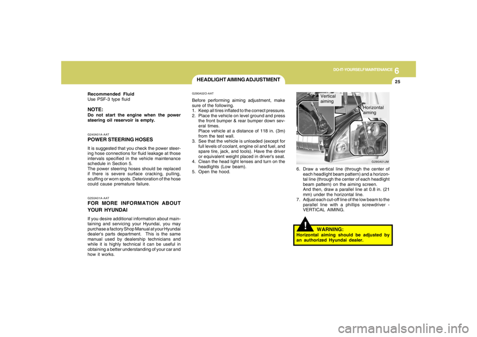
6. Draw a vertical line (through the center of
each headlight beam pattern) and a horizon-
tal line (through the center of each headlight
beam pattern) on the aiming screen.
And then, draw a parallel line at 0.8 in. (21
mm) under the horizontal line.
7. Adjust each cut-off line of the low beam to the
parallel line with a phillips screwdriver -
VERTICAL AIMING.
WARNING:
Horizontal aiming should be adjusted by
an authorized Hyundai dealer.
G290A02O-AATBefore performing aiming adjustment, make
sure of the following.
1. Keep all tires inflated to the correct pressure.
2. Place the vehicle on level ground and press
the front bumper & rear bumper down sev-
eral times.
Place vehicle at a distance of 118 in. (3m)
from the test wall.
3. See that the vehicle is unloaded (except for
full levels of coolant, engine oil and fuel, and
spare tire, jack, and tools). Have the driver
or equivalent weight placed in driver's seat.
4. Clean the head light lenses and turn on the
headlights (Low beam).
5. Open the hood.
G250A01A-AATFOR MORE INFORMATION ABOUT
YOUR HYUNDAIIf you desire additional information about main-
taining and servicing your Hyundai, you may
purchase a factory Shop Manual at your Hyundai
dealer's parts department. This is the same
manual used by dealership technicians and
while it is highly technical it can be useful in
obtaining a better understanding of your car and
how it works.G240A01A-AATPOWER STEERING HOSESIt is suggested that you check the power steer-
ing hose connections for fluid leakage at those
intervals specified in the vehicle maintenance
schedule in Section 5.
The power steering hoses should be replaced
if there is severe surface cracking, pulling,
scuffing or worn spots. Deterioration of the hose
could cause premature failure. Recommended Fluid
Use PSF-3 type fluidNOTE:Do not start the engine when the power
steering oil reservoir is empty.
G290A01JM
Vertical
aiming
Horizontal
aiming
Page 232 of 273
6
DO-IT-YOURSELF MAINTENANCE
26
REPLACEMENT OF LIGHT BULBS!
G260A02A-AATBefore attempting to replace a light bulb, be sure
the switch is turned to the "OFF" position.
The next paragraph shows how to reach the
light bulbs so they may be changed. Be sure to
replace the burned-out bulb with one of the
same number and wattage rating.
See page 6-34 for the wattage description.
CAUTION:
Keep the lamps out of contact with petro-
leum products, such as oil, gasoline, etc.
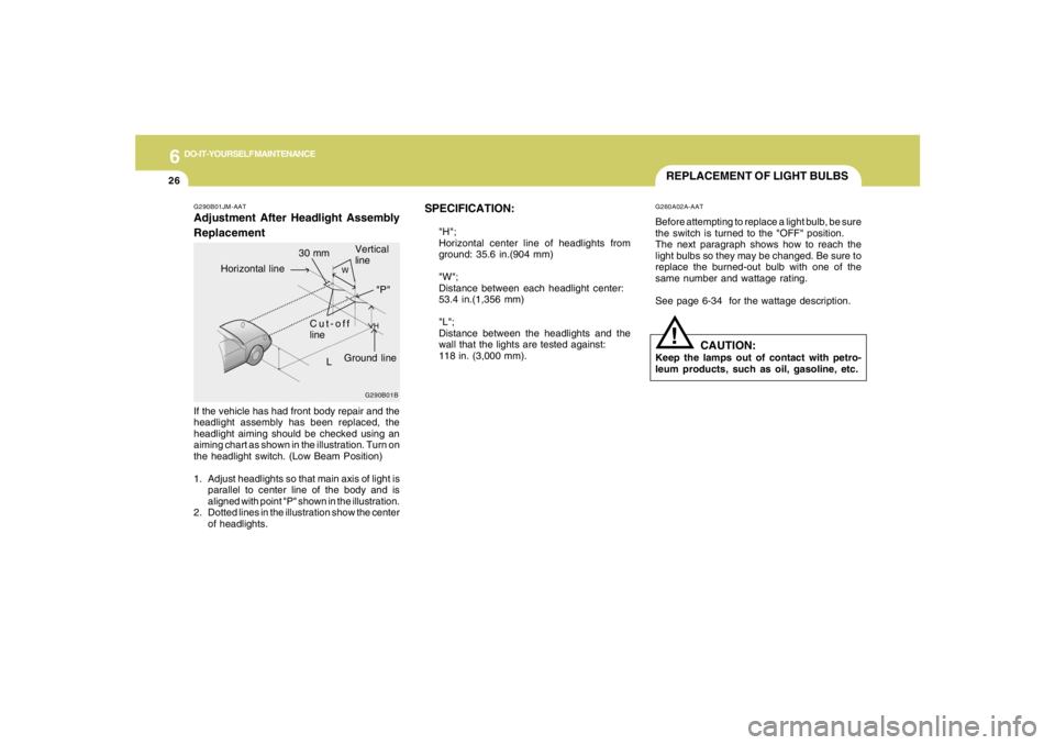
SPECIFICATION:
"H";
Horizontal center line of headlights from
ground: 35.6 in.(904 mm)
"W";
Distance between each headlight center:
53.4 in.(1,356 mm)
"L";
Distance between the headlights and the
wall that the lights are tested against:
118 in. (3,000 mm).
G290B01JM-AATAdjustment After Headlight Assembly
ReplacementIf the vehicle has had front body repair and the
headlight assembly has been replaced, the
headlight aiming should be checked using an
aiming chart as shown in the illustration. Turn on
the headlight switch. (Low Beam Position)
1. Adjust headlights so that main axis of light is
parallel to center line of the body and is
aligned with point "P" shown in the illustration.
2. Dotted lines in the illustration show the center
of headlights.
G290B01B
L
W
H
Cut-off
line
Ground line
"P" Horizontal line
Vertical
line
30 mm
Page 233 of 273
6
DO-IT-YOURSELF MAINTENANCE
27
HJM5016HJM5013
HJM5017 G270A02O-AAT
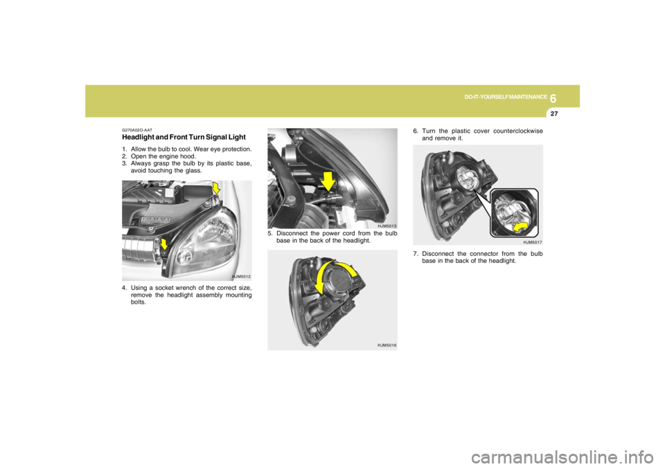
Headlight and Front Turn Signal Light1. Allow the bulb to cool. Wear eye protection.
2. Open the engine hood.
3. Always grasp the bulb by its plastic base,
avoid touching the glass.
4. Using a socket wrench of the correct size,
remove the headlight assembly mounting
bolts.
HJM5012
6. Turn the plastic cover counterclockwise
and remove it.
5. Disconnect the power cord from the bulb
base in the back of the headlight.
7. Disconnect the connector from the bulb
base in the back of the headlight.
Page 234 of 273
6
DO-IT-YOURSELF MAINTENANCE
28
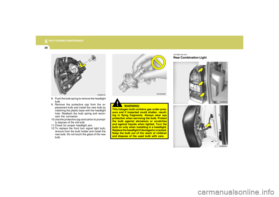
G270B01JM-AATRear Combination Light
!
WARNING:
This halogen bulb contains gas under pres-
sure and if impacted could shatter, result-
ing in flying fragments. Always wear eye
protection when servicing the bulb. Protect
the bulb against abrasions or scratches
and against liquids when lighted. Turn the
bulb on only when installing in a headlight.
Replace the headlight if damaged or cracked.
Keep the bulb out of the reach of children
and dispose of the used bulb with care. 8. Push the bulb spring to remove the headlight
bulb.
9. Remove the protective cap from the re-
placement bulb and install the new bulb by
matching the plastic base with the headlight
hole. Reattach the bulb spring and recon-
nect the connector.
10.Use the protective cap and carton to prompt-
ly dispose of the old bulb.
11.Check for proper headlight aim.
12.To replace the front turn signal light bulb,
remove from the bulb holder and install the
new bulb. Do not touch the glass of the new
bulb.
HJM5018
G270A03O
HJM5020
HJM5021
Page 235 of 273
6
DO-IT-YOURSELF MAINTENANCE
29
HJM5022(1)
(2)
(3)
(4)
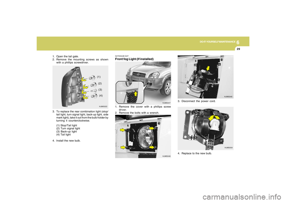
G270I02JM-GATFront fog Light (If installed)
HJM5047
1. Remove the cover with a phillips screw
driver.
2. Remove the bolts with a wrench.3. Disconnect the power cord.
HJM5049
HJM5050
4. Replace to the new bulb.
HJM5048
1. Open the tail gate.
2. Remove the mounting screws as shown
with a phillips screwdriver.
3. To replace the rear combination light (stop/
tail light, turn signal light, back-up light, side
mark light), take it out from the bulb holder by
turning it counterclockwise.
(1) Stop/Tail light
(2) Turn signal light
(3) Back-up light
(4) Tail light
4. Install the new bulb.
Page 236 of 273
6
DO-IT-YOURSELF MAINTENANCE
30
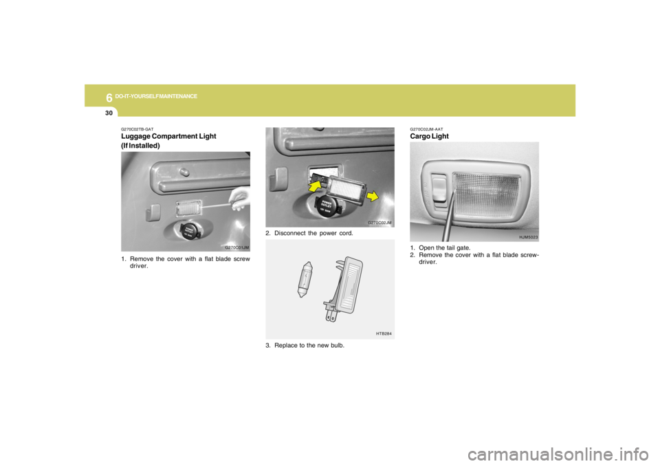
G270C02JM-AATCargo Light1. Open the tail gate.
2. Remove the cover with a flat blade screw-
driver.
3. Replace to the new bulb.
HTB284
G270C02TB-GATLuggage Compartment Light
(If Installed)
G270C01JM
1. Remove the cover with a flat blade screw
driver.2. Disconnect the power cord.
G270C02JM
HJM5023
Page 237 of 273
6
DO-IT-YOURSELF MAINTENANCE
31
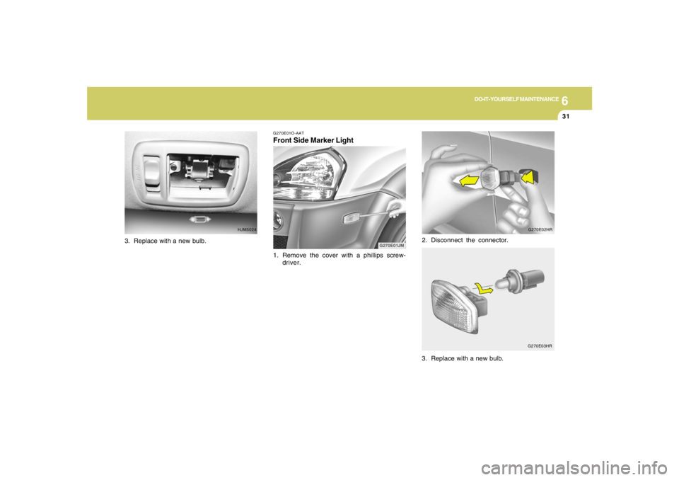
G270E01JM G270E01O-AAT
Front Side Marker Light1. Remove the cover with a phillips screw-
driver.2. Disconnect the connector.
3. Replace with a new bulb.
HJM5024G270E02HR
G270E03HR
3. Replace with a new bulb.
Page 238 of 273
6
DO-IT-YOURSELF MAINTENANCE
32
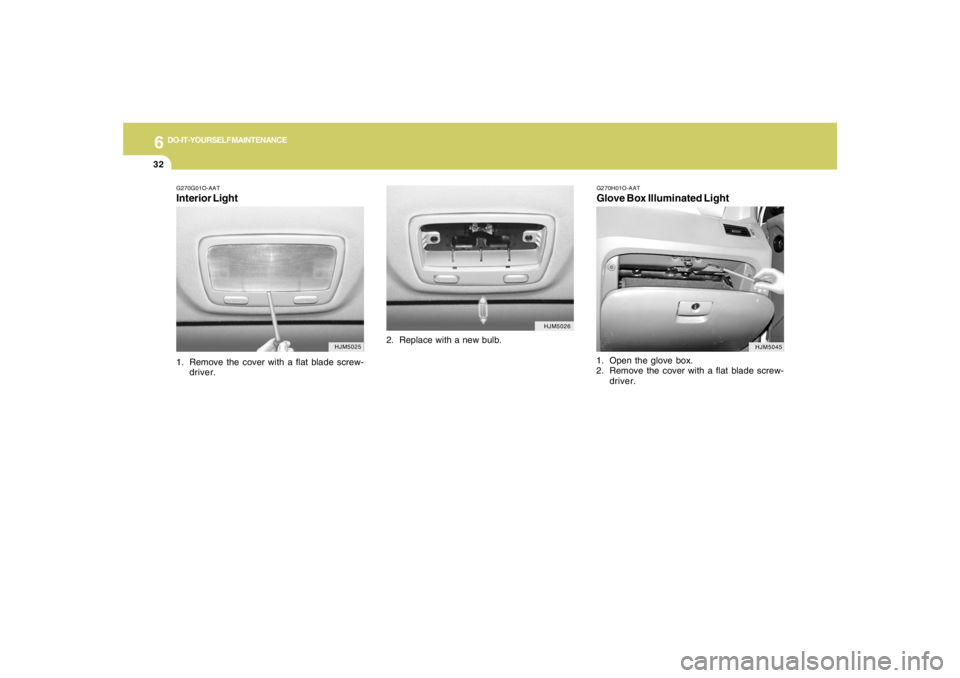
G270G01O-AATInterior Light1. Remove the cover with a flat blade screw-
driver.
G270H01O-AATGlove Box Illuminated Light1. Open the glove box.
2. Remove the cover with a flat blade screw-
driver.
HJM5025HJM5026
HJM5045
2. Replace with a new bulb.
Page 239 of 273
6
DO-IT-YOURSELF MAINTENANCE
33
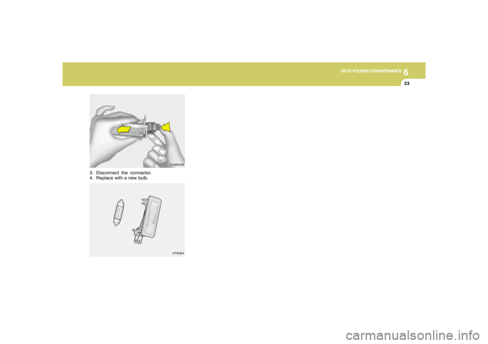
3. Disconnect the connector.
4. Replace with a new bulb.
HJM5039
HTB284
Page 240 of 273
6
DO-IT-YOURSELF MAINTENANCE
34
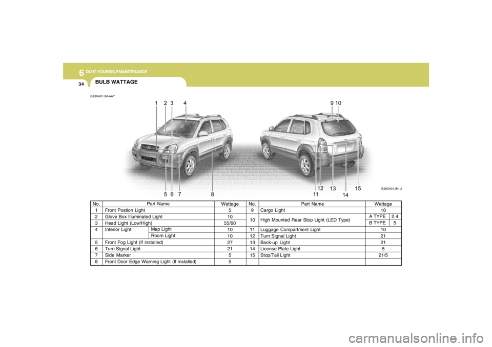
BULB WATTAGEG280A01JM-AAT
Part Name
Front Postion Light
Glove Box Illuminated Light
Head Light (Low/High)
Interior Light
Front Fog Light (If installed)
Turn Signal Light
Side Marker
Front Door Edge Warning Light (If installed) No.
1
2
3
4
5
6
7
8Wattage
5
10
55/60
10
10
27
21
5
5Wattage
10
10
21
21
5
21/5 No.
9
10
11
12
13
14
15
Part Name
Cargo Light
High Mounted Rear Stop Light (LED Type)
Luggage Compartment Light
Turn Signal Light
Back-up Light
License Plate Light
Stop/Tail Light Map Light
Room Light
A TYPE
B TYPE2.4
5
G280A01JM-U
Trending: oil filter, warning light, fuel, emergency towing, charging, width, oil level


