HYUNDAI TUCSON 2014 Owners Manual
Manufacturer: HYUNDAI, Model Year: 2014, Model line: TUCSON, Model: HYUNDAI TUCSON 2014Pages: 542, PDF Size: 7.59 MB
Page 501 of 542
7-71
7
Maintenance
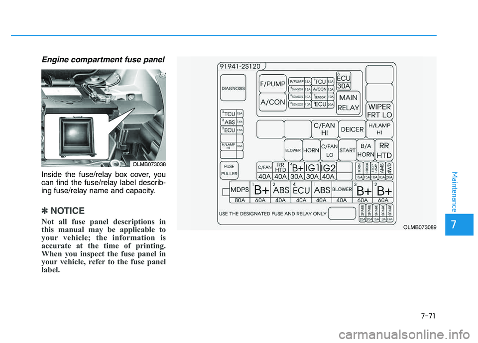
Engine compartment fuse panel
Inside the fuse/relay box cover, you
can find the fuse/relay label describ-
ing fuse/relay name and capacity.
✽✽NOTICE
Not all fuse panel descriptions in
this manual may be applicable to
your vehicle; the information is
accurate at the time of printing.
When you inspect the fuse panel in
your vehicle, refer to the fuse panel
label.
OLMB073038
OLMB073089
Page 502 of 542
7-72
Maintenance
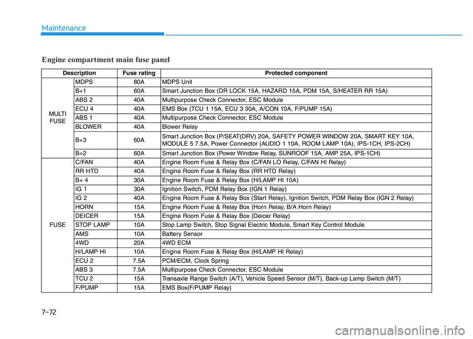
Engine compartment main fuse panel
Description Fuse ratingProtected component
MULTI FUSE MDPS 80A MDPS Unit
B+1 60A Smart Junction Box (DR LOCK 15A, HAZARD 15A, PDM 15A, S/HEATER RR 15A)
ABS 2 40A Multipurpose Check Connector, ESC Module
ECU 4 40A EMS Box (TCU 1 15A, ECU 3 30A, A/CON 10A, F/PUMP 15A)
ABS 1 40A Multipurpose Check Connector, ESC Module
BLOWER 40A Blower Relay
B+3 60A
Smart Junction Box (P/SEAT(DRV) 20A, SAFETY POWER WINDOW 20A, SMART KEY 10A,
MODULE 5 7.5A, Power Connector (AUDIO 1 10A, ROOM LAMP 10A), IPS-1CH, IPS-2CH)
B+2 60A Smart Junction Box (Power Window Relay, SUNROOF 15A, AMP 25A, IPS-1CH)
FUSE C/FAN 40A Engine Room Fuse & Relay Box (C/FAN LO Relay, C/FAN HI Relay)
RR HTD 40A Engine Room Fuse & Relay Box (RR HTD Relay)
B+ 4 30A Engine Room Fuse & Relay Box (H/LAMP HI 10A)
IG 1 30A Ignition Switch, PDM Relay Box (IGN 1 Relay)
IG 2 40A Engine Room Fuse & Relay Box (Start Relay), Ignition Switch, PDM Relay Box (IGN 2 Relay)
HORN 15A Engine Room Fuse & Relay Box (Horn Relay, B/A Horn Relay)
DEICER 15A Engine Room Fuse & Relay Box (Deicer Relay)
STOP LAMP 10A Stop Lamp Switch, Stop Signal Electric Module, Smart Key Control Module
AMS 10A Battery Sensor
4WD 20A 4WD ECM
H/LAMP HI 10A Engine Room Fuse & Relay Box (H/LAMP HI Relay)
ECU 2 7.5A PCM/ECM, Clock Spring
ABS 3 7.5A Multipurpose Check Connector, ESC Module
TCU 2 15A Transaxle Range Switch (A/T), Vehicle Speed Sensor (M/T), Back-up Lamp Switch (M/T)
F/PUMP 15A EMS Box(F/PUMP Relay)
Page 503 of 542
7-73
7
Maintenance
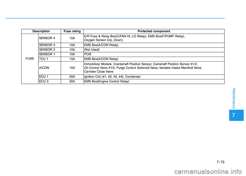
Description Fuse ratingProtected component
FUSE SENSOR 4 15A
E/R Fuse & Relay Box(C/FAN HI, LO Relay), EMS Box(F/PUMP Relay),
Oxygen Sensor (Up, Down)
SENSOR 3 10A EMS Box(A/CON Relay)
SENSOR 2 10A (Not Used)
SENSOR 1 10A PCM
TCU 1 15A EMS Box(A/CON Relay)
A/CON 10A Immobilizer Module, Crankshaft Position Sensor, Camshaft Position Sensor #1/2,
Oil Control Valve #1/2, Purge Control Solenoid Valve, Variable Intake Manifold Valve,
Canister Close Valve
ECU 1 20A Ignition Coil (#1, #2, #3, #4), Condenser
ECU 3 30A EMS Box(Engine Control Relay)
Page 504 of 542
7-74
Maintenance
LLIIGG HH TT BB UU LLBB SS
Consult an authorized HYUNDAI
dealer to replace most vehicle light
bulbs. It is difficult to replace vehicle
light bulbs because other parts of the
vehicle must be removed before you
can get to the bulb. This is especially
true for removing the headlight
assembly to get to the bulb(s).
Removing/installing the headlight
assembly can result in damage to
the vehicle.
✽✽
NOTICE
After heavy driving, rain or wash-
ing, headlight and taillight lenses
could appear frosty. This condition
is caused by the temperature differ-
ence between the lamp inside and
the outside temperature. This is sim-
ilar to the condensation on your win-
dows inside your vehicle during the
rain and doesn’t indicate a problem
with your vehicle. If the water leaks
into the lamp bulb circuitry, have
your vehicle checked by an author-
ized HYUNDAI dealer.
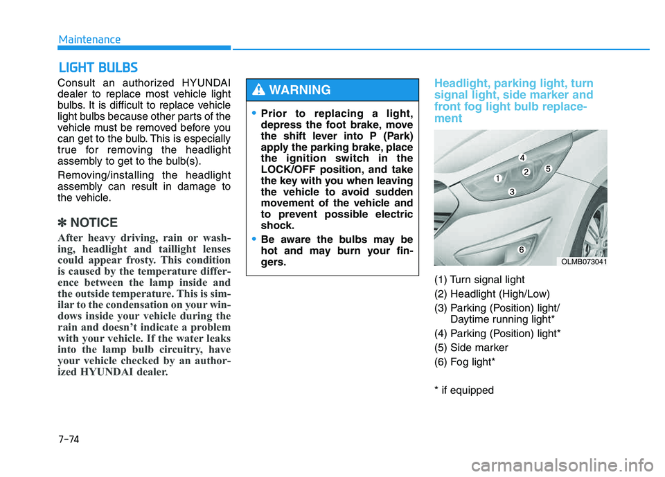
Headlight, parking light, turn
signal light, side marker and
front fog light bulb replace- ment
(1) Turn signal light
(2) Headlight (High/Low)
(3) Parking (Position) light/ Daytime running light*
(4) Parking (Position) light*
(5) Side marker
(6) Fog light* * if equipped
Prior to replacing a light,
depress the foot brake, move
the shift lever into P (Park)
apply the parking brake, place
the ignition switch in the
LOCK/OFF position, and take
the key with you when leaving
the vehicle to avoid sudden
movement of the vehicle and
to prevent possible electric
shock.
Be aware the bulbs may be
hot and may burn your fin-
gers.
WARNING
OLMB073041
Page 505 of 542
7-75
7
Maintenance
Headlight
Halogen bulb
Always handle them carefully, andavoid scratches and abrasions. If
the bulbs are lit, avoid contact with
liquids.
Never touch the glass with bare hands. Residual oil may cause the
bulb to overheat and burst when lit.
A bulb should be operated only when installed in a headlamp.
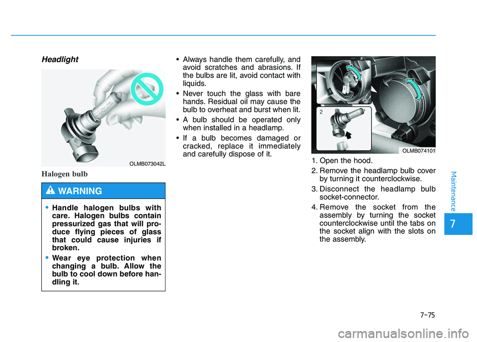
If a bulb becomes damaged or cracked, replace it immediatelyand carefully dispose of it. 1. Open the hood.
2. Remove the headlamp bulb cover
by turning it counterclockwise.
3. Disconnect the headlamp bulb socket-connector.
4. Remove the socket from the assembly by turning the socket
counterclockwise until the tabs on
the socket align with the slots on
the assembly.
OLMB073042L
Handle halogen bulbs with
care. Halogen bulbs contain
pressurized gas that will pro-
duce flying pieces of glassthat could cause injuries if
broken.
Wear eye protection when
changing a bulb. Allow the
bulb to cool down before han-dling it.
WARNING
OLMB074101
Page 506 of 542
7-76
Maintenance
5. Remove the bulb by pulling it out.
6. Insert a new bulb into the socket.
7. Install the socket in the assemblyby aligning the tabs on the socket
with the slots in the assembly.
Push the socket into the assembly
and turn the socket clockwise.
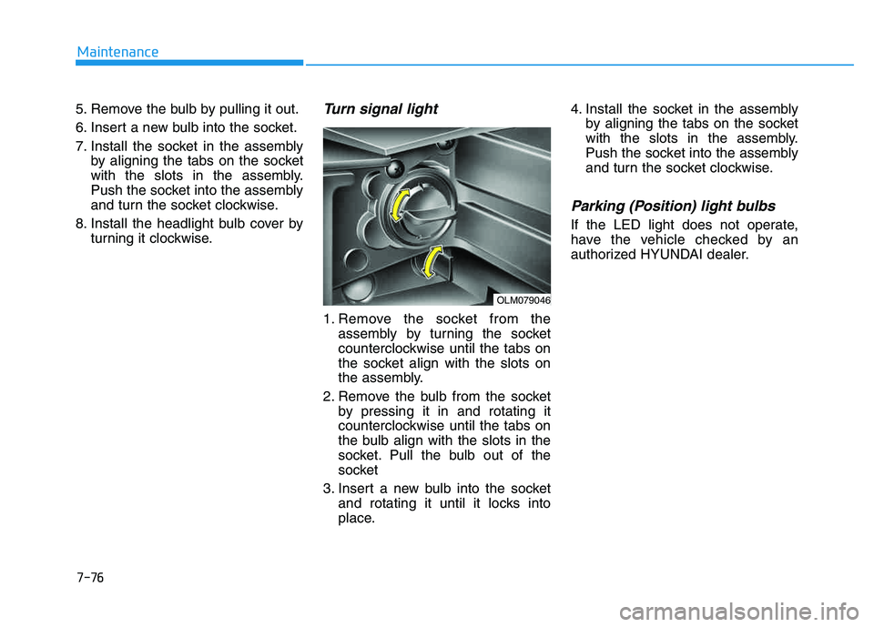
8. Install the headlight bulb cover by turning it clockwise.Turn signal light
1. Remove the socket from theassembly by turning the socket
counterclockwise until the tabs on
the socket align with the slots on
the assembly.
2. Remove the bulb from the socket by pressing it in and rotating it
counterclockwise until the tabs on
the bulb align with the slots in the
socket. Pull the bulb out of the
socket
3. Insert a new bulb into the socket and rotating it until it locks into
place. 4. Install the socket in the assembly
by aligning the tabs on the socket
with the slots in the assembly.
Push the socket into the assembly
and turn the socket clockwise.
Parking (Position) light bulbs
If the LED light does not operate,
have the vehicle checked by an
authorized HYUNDAI dealer.
OLM079046
Page 507 of 542
7-77
7
Maintenance
Fog light bulbs
1. Remove the front bumper undercover.
2. Reach your hand into the back of the front bumper.
3. Disconnect the power connector from the socket.
4. Remove the bulb-socket from the housing by turning the socket
counter clockwise until the tabs on
the socket align with the slots onthe housing.
5. Install the new bulb-socket into the housing by aligning the tabs on
the socket with the slots in the
housing. Push the socket into the
housing and turn the socket clock-
wise.
6. Connect the power connector to the socket.
7. Reinstall the front bumper under cover.
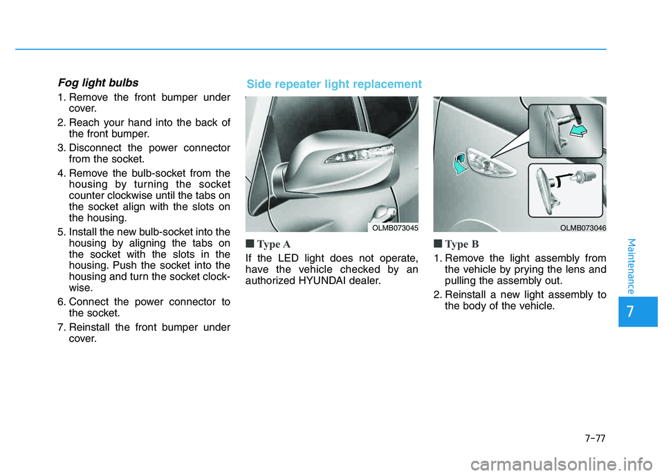
■■Type A
If the LED light does not operate,
have the vehicle checked by an
authorized HYUNDAI dealer.
■■Type B
1. Remove the light assembly from
the vehicle by prying the lens and
pulling the assembly out.
2. Reinstall a new light assembly to the body of the vehicle.
OLMB073045OLMB073046
Side repeater light replacement
Page 508 of 542
7-78
Maintenance
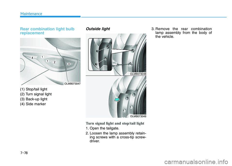
Rear combination light bulb replacement
(1) Stop/tail light
(2) Turn signal light
(3) Back-up light
(4) Side marker
Outside light
Turn signal light and stop/tail light
1. Open the tailgate.
2. Loosen the lamp assembly retain-ing screws with a cross-tip screw-
driver. 3. Remove the rear combination
lamp assembly from the body of
the vehicle.
OLMB073047
OLMB073048
OLMB073049
Page 509 of 542
7-79
7
Maintenance
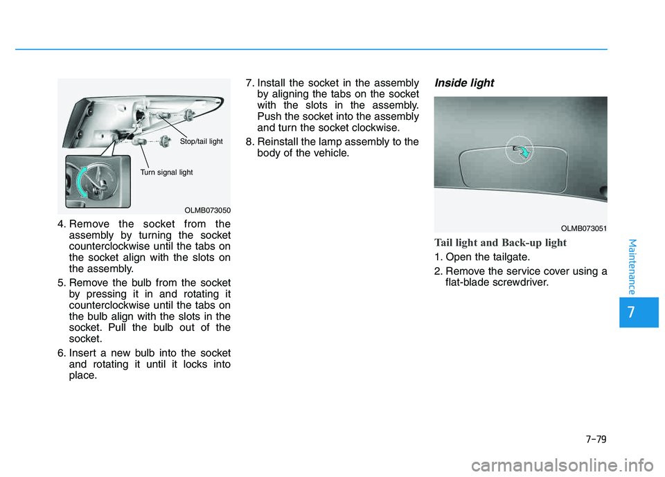
4. Remove the socket from theassembly by turning the socket
counterclockwise until the tabs on
the socket align with the slots on
the assembly.
5. Remove the bulb from the socket by pressing it in and rotating it
counterclockwise until the tabs on
the bulb align with the slots in the
socket. Pull the bulb out of the
socket.
6. Insert a new bulb into the socket and rotating it until it locks into
place. 7. Install the socket in the assembly
by aligning the tabs on the socket
with the slots in the assembly.
Push the socket into the assembly
and turn the socket clockwise.
8. Reinstall the lamp assembly to the body of the vehicle.
Inside light
Tail light and Back-up light
1. Open the tailgate.
2. Remove the service cover using aflat-blade screwdriver.
OLMB073050
Turn signal light
Stop/tail light
OLMB073051
Page 510 of 542
7-80
Maintenance
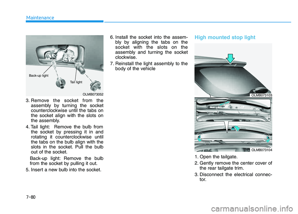
3. Remove the socket from theassembly by turning the socket
counterclockwise until the tabs on
the socket align with the slots on
the assembly.
4. Tail light: Remove the bulb from the socket by pressing it in and
rotating it counterclockwise until
the tabs on the bulb align with the
slots in the socket. Pull the bulb
out of the socket.
Back-up light: Remove the bulb
from the socket by pulling it out.
5. Insert a new bulb into the socket. 6. Install the socket into the assem-
bly by aligning the tabs on the
socket with the slots on the
assembly and turning the socket
clockwise.
7. Reinstall the light assembly to the body of the vehicle
High mounted stop light
1. Open the tailgate.
2. Gently remove the center cover ofthe rear tailgate trim.
3. Disconnect the electrical connec- tor.
OLMB073052
Back-up light
Tail light
OLMB073103
OLMB073104