oil HYUNDAI TUCSON 2015 Owner's Guide
[x] Cancel search | Manufacturer: HYUNDAI, Model Year: 2015, Model line: TUCSON, Model: HYUNDAI TUCSON 2015Pages: 653, PDF Size: 8.45 MB
Page 568 of 653

7-27
7
Maintenance
EENN GGIINN EE OO IILL
Checking the engine oil level
1. Follow all of the oil manufacturer’s
precautions.
2. Be sure the vehicle is on level ground in P (Park) with the parking
brake set and the wheels blocked.
3. Turn the engine on and allow the engine to reach normal operating
temperature.
4. Turn the engine off and wait about five minutes for the oil to return tothe oil pan.
5. Pull the dipstick out, wipe it clean, and re-insert it fully.
6. Pull the dipstick out again andcheck the level. The level should
be between F and L.
7. If it is near or at L, add enough oil to bring the level to F.
✽✽ NOTICE
To prevent damage to your engine:
Do not overfill with engine oil. Add oil in small quantities and
recheck level to ensure engine is
not overfilled.
Do not spill engine oil when adding or changing engine oil. Use
a funnel to help prevent oil from
being spilled on engine compo-
nents. Wipe off spilled oil immedi-
ately
OLMB073096
OLMB073095
■NU 2.0L
■Theta II 2.4L
Page 569 of 653
7-28
Maintenance
✽✽NOTICE
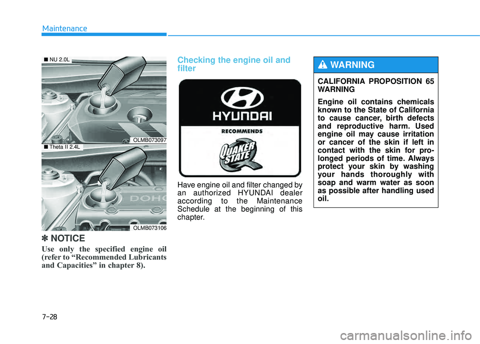
Use only the specified engine oil
(refer to “Recommended Lubricants
and Capacities” in chapter 8).
Checking the engine oil and filter
Have engine oil and filter changed by
an authorized HYUNDAI dealeraccording to the MaintenanceSchedule at the beginning of this
chapter.
OLMB073097
OLMB073106
■ NU 2.0L
■Theta II 2.4L
CALIFORNIA PROPOSITION 65
WARNING
Engine oil contains chemicals
known to the State of California
to cause cancer, birth defects
and reproductive harm. Used
engine oil may cause irritationor cancer of the skin if left in
contact with the skin for pro-
longed periods of time. Always
protect your skin by washing
your hands thoroughly withsoap and warm water as soon
as possible after handling usedoil.
WARNING
Page 574 of 653
7-33
7
Maintenance
✽✽NOTICE
Use only the specified brake fluid
(refer to “Recommended Lubricants
and Capacities” in chapter 8).
Do not allow brake fluid to
contact the vehicle’s body
paint, as paint damage willresult.
Brake fluid, which has been
exposed to open air for an
extended time should NEVERbe used as its quality cannot
be guaranteed. It should be
disposed of properly.
Do not use the wrong kind of
brake fluid. A few drops of
mineral based oil, such as
engine oil, in your brake sys-
tem can damage brake sys-
tem parts.
CAUTION
Page 577 of 653

7-36
Maintenance
AAIIRR CC LLEE AA NN EERR
Filter replacement
The air cleaner filter can be cleaned
for inspection using compressed air.
Do not attempt to wash or to rinse it,
as water will damage the filter. If
soiled, the air cleaner filter must bereplaced. 1. Loosen the air cleaner cover
attaching clips and open the cover.
2. Wipe the inside of the air cleaner. 3. Replace the air cleaner filter.
4. Lock the cover with the cover
attaching clips.
OLMB073012
OLMB073013OLMB073014
Page 586 of 653

7-45
7
Maintenance
Battery rechargingBy jump starting
After a jump start from a good bat-
tery, drive the vehicle for 20-30 min-
utes before it is shutoff. The vehicle
may not restart if you shut it off
before the battery had a chance to
adequately recharge. See “Jump
Starting” in chapter 6 for more infor-
mation on jump starting procedures.
✽✽NOTICE
An inappropriately disposedbattery can be harmful to
the environment and human
health. Dispose the battery
according to your local
law(s) or regulation.
Always follow these instruc-
tions when recharging your
vehicle’s battery to avoid the
risk of SERIOUS INJURY or
DEATH from explosions or acid
burns:
Before performing mainte-
nance or recharging the bat-
tery, turn off all accessories
and place the ignition switchin the LOCK/OFF position.
Keep all flames, sparks, or
smoking materials away from
the battery.
Always work outdoors or in an area with plenty of ventilation.
Wear eye protection when
checking the battery during
charging.
The battery must be removed
from the vehicle and placed ina well ventilated area.
(Continued)
WARNING
(Continued)
Watch the battery during
charging, and stop or reduce
the charging rate if the battery
cells begin boiling violently.
The negative battery cable
must be removed first and
installed last when the battery
is disconnected. Disconnect
the battery charger in the fol-
lowing order:
(1) Turn off the battery charg-er main switch.
(2) Unhook the negative
clamp from the negative
battery terminal.
(3) Unhook the positive clamp from the positive batteryterminal.
Always use a genuine
HYUNDAI approved battery
when you replace the battery.
Page 598 of 653

7-57
7
Maintenance
Tire terminology and defini- tions
Air Pressure
The amount of air inside the tire
pressing outward on the tire. Air
pressure is expressed in pounds per
square inch (psi) or kilopascal (kPa).
Accessory Weight
This means the combined weight of
optional accessories. Some exam-
ples of optional accessories are
automatic transmission, power
seats, and air conditioning.
Aspect Ratio
The relationship of a tire's height toits width.
Belt
A rubber coated layer of cords that is
located between the plies and the
tread. Cords may be made from steel
or other reinforcing materials.
Bead
The tire bead contains steel wires
wrapped by steel cords that hold the
tire onto the rim.
Bias Ply Tire
A pneumatic tire in which the plies
are laid at alternate angles less than
90 degrees to the centerline of thetread.
Cold Tire Pressure
The amount of air pressure in a tire,measured in pounds per square inch
(psi) or kilopascals (kPa) before a tire
has built up heat from driving.
Curb Weight
This means the weight of a motor
vehicle with standard and optional
equipment including the maximum
capacity of fuel, oil and coolant, but
without passengers and cargo.
DOT Markings
A code molded into the sidewall of atire signifying that the tire is in com-
pliance with the U.S. Department of
Transportation motor vehicle safety
standards. The DOT code includes
the Tire Identification Number (TIN),
an alphanumeric designator which
can also identify the tire manufactur-
er, production plant, brand and dateof production.
Page 604 of 653
7-63
7
Maintenance
FFUU SSEE SS
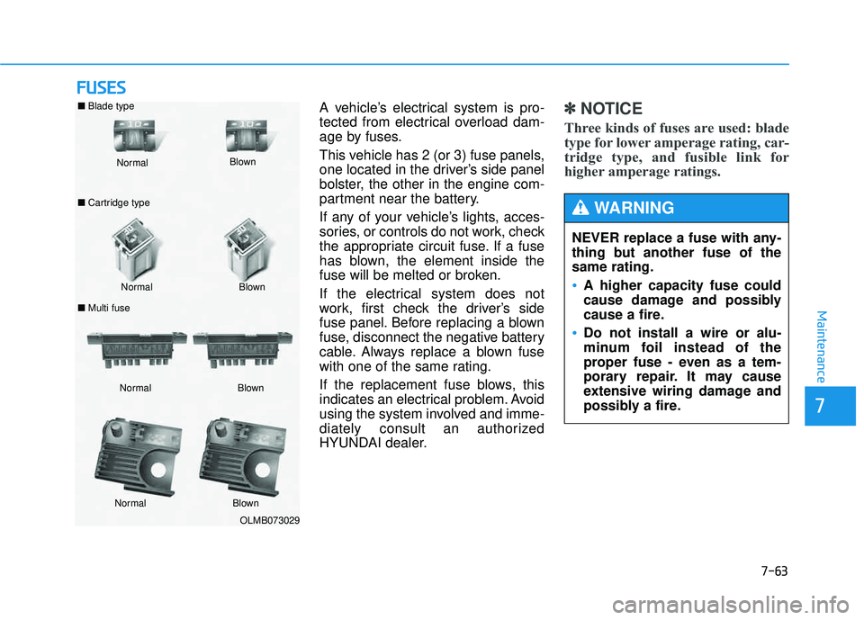
A vehicle’s electrical system is pro-
tected from electrical overload dam-
age by fuses.
This vehicle has 2 (or 3) fuse panels,
one located in the driver’s side panel
bolster, the other in the engine com-
partment near the battery.
If any of your vehicle’s lights, acces-
sories, or controls do not work, check
the appropriate circuit fuse. If a fuse
has blown, the element inside the
fuse will be melted or broken.
If the electrical system does not
work, first check the driver’s side
fuse panel. Before replacing a blown
fuse, disconnect the negative battery
cable. Always replace a blown fuse
with one of the same rating.
If the replacement fuse blows, this
indicates an electrical problem. Avoid
using the system involved and imme-
diately consult an authorized
HYUNDAI dealer.✽✽
NOTICE
Three kinds of fuses are used: blade
type for lower amperage rating, car-
tridge type, and fusible link for
higher amperage ratings.
NEVER replace a fuse with any-
thing but another fuse of thesame rating.
A higher capacity fuse could
cause damage and possibly
cause a fire.
Do not install a wire or alu-
minum foil instead of the
proper fuse - even as a tem-
porary repair. It may cause
extensive wiring damage and
possibly a fire.
WARNING
OLMB073029
Normal
Normal
■
Blade type
■ Cartridge type
■ Multi fuse Blown
Blown
Normal Blown
Normal Blown
Page 614 of 653
7-73
7
Maintenance
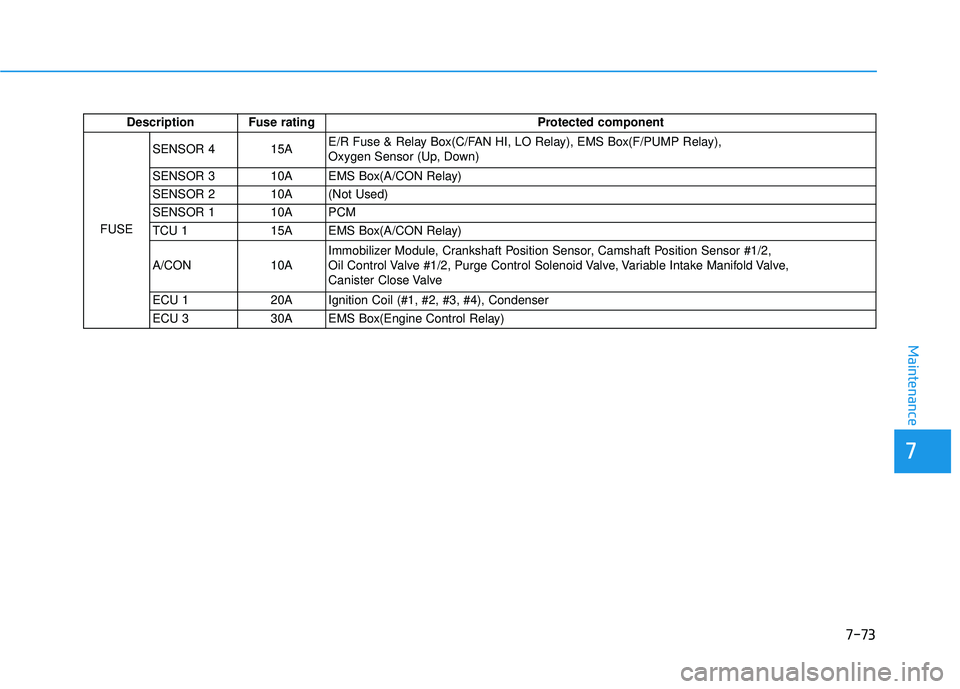
Description Fuse ratingProtected component
FUSE SENSOR 4 15A
E/R Fuse & Relay Box(C/FAN HI, LO Relay), EMS Box(F/PUMP Relay),
Oxygen Sensor (Up, Down)
SENSOR 3 10A EMS Box(A/CON Relay)
SENSOR 2 10A (Not Used)
SENSOR 1 10A PCM
TCU 1 15A EMS Box(A/CON Relay)
A/CON 10A Immobilizer Module, Crankshaft Position Sensor, Camshaft Position Sensor #1/2,
Oil Control Valve #1/2, Purge Control Solenoid Valve, Variable Intake Manifold Valve,
Canister Close Valve
ECU 1 20A Ignition Coil (#1, #2, #3, #4), Condenser
ECU 3 30A EMS Box(Engine Control Relay)
Page 616 of 653

7-75
7
Maintenance
Headlight
Halogen bulb
Always handle them carefully, andavoid scratches and abrasions. If
the bulbs are lit, avoid contact with
liquids.
Never touch the glass with bare hands. Residual oil may cause the
bulb to overheat and burst when lit.
A bulb should be operated only when installed in a headlamp.
If a bulb becomes damaged or cracked, replace it immediatelyand carefully dispose of it. 1. Open the hood.
2. Remove the headlamp bulb cover
by turning it counterclockwise.
3. Disconnect the headlamp bulb socket-connector.
4. Remove the socket from the assembly by turning the socket
counterclockwise until the tabs on
the socket align with the slots on
the assembly.
OLMB073042L
Handle halogen bulbs with
care. Halogen bulbs contain
pressurized gas that will pro-
duce flying pieces of glassthat could cause injuries if
broken.
Wear eye protection when
changing a bulb. Allow the
bulb to cool down before han-dling it.
WARNING
OLMB074101
Page 622 of 653

7-81
7
Maintenance
4. Loosen the retaining nuts andremove the spoiler.
5. Remove the high mounted stop light assembly (A) after loosening
the nuts and washer nozzle (B).
6. Reinstall a new light assembly in the reverse order of removal.
License plate light bulb replacement
1. Loosen the lens retaining screwswith a philips head screwdriver.
2. Remove the lens.
3. Remove the bulb by pulling it straight out.
4. Install a new bulb.
5. Reinstall the lens securely with the lens retaining screws.
OLMB073105
A
B
OLMB073054