ABS HYUNDAI VELOSTER 2015 User Guide
[x] Cancel search | Manufacturer: HYUNDAI, Model Year: 2015, Model line: VELOSTER, Model: HYUNDAI VELOSTER 2015Pages: 384, PDF Size: 25 MB
Page 329 of 384
753
Maintenance
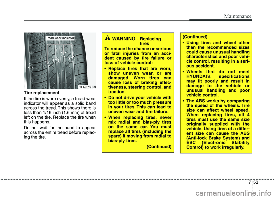
Tire replacement
If the tire is worn evenly, a tread wear
indicator will appear as a solid band
across the tread. This shows there is
less than 1/16 inch (1.6 mm) of tread
left on the tire. Replace the tire when
this happens.
Do not wait for the band to appear
across the entire tread before replac-
ing the tire.
OEN076053
Tread wear indicatorWARNING - Replacing
tires
To reduce the chance or serious
or fatal injuries from an acci-
dent caused by tire failure or
loss of vehicle control:
Replace tires that are worn,
show uneven wear, or are
damaged. Worn tires can
cause loss of braking effec-
tiveness, steering control, and
traction.
Do not drive your vehicle with
too little or too much pressure
in your tires. This can lead to
uneven wear and tire failure.
When replacing tires, never
mix radial and bias-ply tires
on the same car. You must
replace all tires (including the
spare) if moving from radial to
bias-ply tires.
(Continued)(Continued)
Using tires and wheel other
than the recommended sizes
could cause unusual handling
characteristics and poor vehi-
cle control, resulting in a seri-
ous accident.
Wheels that do not meet
HYUNDAI’s specifications
may fit poorly and result in
damage to the vehicle or
unusual handling and poor
vehicle control.
The ABS works by comparing
the speed of the wheels. Tire
size can affect wheel speed.
When replacing tires, all 4
tires must use the same size
originally supplied with the
vehicle. Using tires of a differ-
ent size can cause the ABS
(Anti-lock Brake System) and
ESC (Electronic Stability
Control) to work irregularly.
Page 344 of 384
Maintenance
68 7
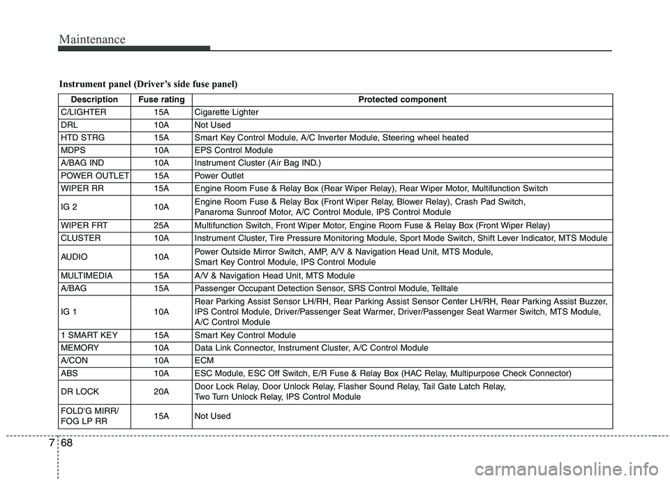
Instrument panel (Driver’s side fuse panel)
Description Fuse rating Protected component
C/LIGHTER 15A Cigarette Lighter
DRL 10A Not Used
HTD STRG 15A Smart Key Control Module, A/C Inverter Module, Steering wheel heated
MDPS 10A EPS Control Module
A/BAG IND 10A Instrument Cluster (Air Bag IND.)
POWER OUTLET 15A Power Outlet
WIPER RR 15A Engine Room Fuse & Relay Box (Rear Wiper Relay), Rear Wiper Motor, Multifunction Switch
IG 2 10AEngine Room Fuse & Relay Box (Front Wiper Relay, Blower Relay), Crash Pad Switch,
Panaroma Sunroof Motor, A/C Control Module, IPS Control Module
WIPER FRT 25A Multifunction Switch, Front Wiper Motor, Engine Room Fuse & Relay Box (Front Wiper Relay)
CLUSTER 10A Instrument Cluster, Tire Pressure Monitoring Module, Sport Mode Switch, Shift Lever Indicator, MTS Module
AUDIO 10APower Outside Mirror Switch, AMP, A/V & Navigation Head Unit, MTS Module,
Smart Key Control Module, IPS Control Module
MULTIMEDIA 15A A/V & Navigation Head Unit, MTS Module
A/BAG 15A Passenger Occupant Detection Sensor, SRS Control Module, Telltale
IG 1 10ARear Parking Assist Sensor LH/RH, Rear Parking Assist Sensor Center LH/RH, Rear Parking Assist Buzzer,
IPS Control Module, Driver/Passenger Seat Warmer, Driver/Passenger Seat Warmer Switch, MTS Module,
A/C Control Module
1 SMART KEY 15A Smart Key Control Module
MEMORY 10A Data Link Connector, Instrument Cluster, A/C Control Module
A/CON 10A ECM
ABS 10A ESC Module, ESC Off Switch, E/R Fuse & Relay Box (HAC Relay, Multipurpose Check Connector)
DR LOCK 20ADoor Lock Relay, Door Unlock Relay, Flasher Sound Relay, Tail Gate Latch Relay,
Two Turn Unlock Relay, IPS Control Module
FOLD'G MIRR/
FOG LP RR15A Not Used
Page 347 of 384
771
Maintenance
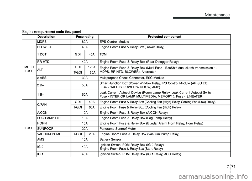
Engine compartment main fuse panel
Description Fuse rating Protected component
MULTI
FUSEMDPS 80A EPS Control Module
BLOWER 40A Engine Room Fuse & Relay Box (Blower Relay)
1 DCT GDI 40A TCM
RR HTD 40A Engine RoomFuse & Relay Box (Rear Defogger Relay)
ALTGDI 125A
Engine RoomFuse & Relay Box (Multi Fuse - EcoShift dual clutch transmission 1,
MDPS, RR HTD, BLOWER), Alternator
T-GDI 150A
2 ABS 30A Multipurpose Check Connector, ESC Module
2 B+ 50ASmart Junction Box (Power Window Relay, IPS Control Module (ARISU LT),
Fuse - SAFETY POWER WINDOW, AMP)
1 B+50ALeak Current Autocut Device (Room Lamp Relay, Leak Current Autocut Switch,
Fuse - INTERIOR LAMP, MULTIMEDIA, MEMORY ), Fuse - S/HEATER
FUSEC/FANGDI 40A Engine Room Fuse & Relay Box (Cooling Fan (High) Relay, Cooling Fan (Low) Relay)
T-GDI 60AEngine Room Fuse & Relay Box (Cooling Fan (High) Relay)
A/CON 10AEngine RoomFuse & Relay Box (A/CON Relay)
FOG LAMP FRT 10AEngine RoomFuse & Relay Box (Fog Lamp Relay)
HORN 15AEngine RoomFuse & Relay Box (Burglar Alarm Horn Relay, Horn Relay)
SUNROOF 20A Panorama Sunroof Motor
VACUUM PUMP T-GDI 20A Engine Room Fuse & Relay Box (Vacuum Pump Relay)
AMS 10A Battery Sensor
IG 2 40AIgnition Switch, PDM Relay Box (IG 2 Relay),
Engine Room Fuse & Relay Box (Start Relay)
IG 1 40A Ignition Switch, PDM Relay Box (IG 1 Relay, ACC Relay)
Page 348 of 384
Maintenance
72 7
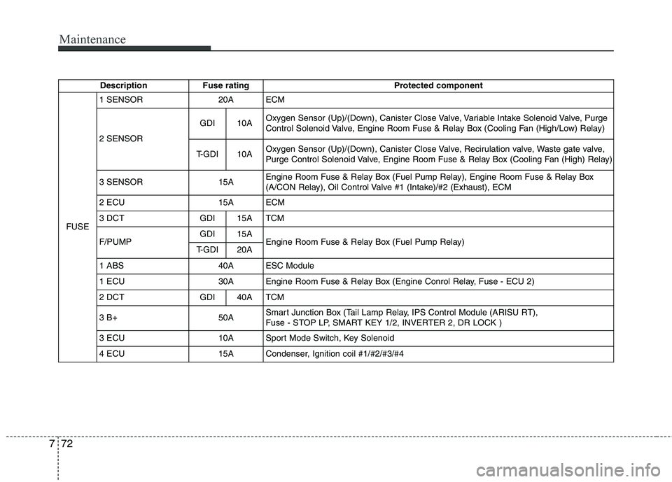
Description Fuse rating Protected component
FUSE1 SENSOR 20A ECM
2 SENSORGDI 10AOxygen Sensor (Up)/(Down), Canister Close Valve, Variable Intake Solenoid Valve, Purge
Control Solenoid Valve, Engine Room Fuse & Relay Box (Cooling Fan (High/Low) Relay)
T-GDI 10AOxygen Sensor (Up)/(Down), Canister Close Valve, Recirulation valve, Waste gate valve,
Purge Control Solenoid Valve, Engine Room Fuse & Relay Box (Cooling Fan (High) Relay)
3 SENSOR 15AEngine Room Fuse & Relay Box (Fuel Pump Relay), Engine Room Fuse & Relay Box
(A/CON Relay), Oil Control Valve #1 (Intake)/#2 (Exhaust), ECM
2 ECU 15A ECM
3 DCT GDI 15A TCM
F/PUMPGDI 15A
Engine Room Fuse & Relay Box (Fuel Pump Relay)
T-GDI 20A
1 ABS 40A ESC Module
1 ECU 30A Engine Room Fuse & Relay Box (Engine Conrol Relay, Fuse - ECU 2)
2 DCT GDI 40A TCM
3 B+ 50ASmart Junction Box (Tail Lamp Relay, IPS Control Module (ARISU RT),
Fuse - STOP LP, SMART KEY 1/2, INVERTER 2, DR LOCK )
3 ECU 10A Sport Mode Switch, Key Solenoid
4 ECU 15A Condenser, Ignition coil #1/#2/#3/#4
Page 352 of 384
Maintenance
76 7
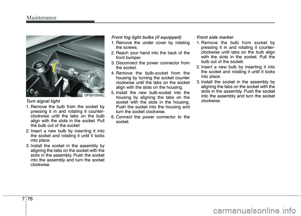
Turn signal light
1. Remove the bulb from the socket by
pressing it in and rotating it counter-
clockwise until the tabs on the bulb
align with the slots in the socket. Pull
the bulb out of the socket
2. Insert a new bulb by inserting it into
the socket and rotating it until it locks
into place.
3. Install the socket in the assembly by
aligning the tabs on the socket with the
slots in the assembly. Push the socket
into the assembly and turn the socket
clockwise.
Front fog light bulbs (if equipped)
1. Remove the under cover by rotating
the screws.
2. Reach your hand into the back of the
front bumper.
3. Disconnect the power connector from
the socket.
4. Remove the bulb-socket from the
housing by turning the socket counter
clockwise until the tabs on the socket
align with the slots on the housing.
5. Install the new bulb-socket into the
housing by aligning the tabs on the
socket with the slots in the housing.
Push the socket into the housing and
turn the socket clockwise.
6. Connect the power connector to the
socket.
Front side marker
1. Remove the bulb from socket by
pressing it in and rotating it counter-
clockwise until tabs on the bulb align
with the slots in the socket. Pull the
bulb out of the socket.
2. Insert a new bulb by inserting it into
the socket and rotating it until it locks
into place.
3. Install the socket in the assembly by
aligning the tabs on the socket with the
slots in the assembly. Push the socket
into the assembly and turn the socket
clockwise.
OFS072042L
Page 354 of 384
Maintenance
78 7
4. Remove the socket from the assembly
by turning the socket counterclockwise
until the tabs on the socket align with the
slots on the assembly.
5. Remove the bulb from the socket.
6. Insert a new bulb by inserting it into the
socket and pushing or rotating it until it
locks into place.
7. Install the socket in the assembly by
aligning the tabs on the socket with the
slots in the assembly. Push the socket
into the assembly and turn the socket
clockwise.
8. Reinstall the light assembly to the body
of the vehicle.
9. Tighten the screws.
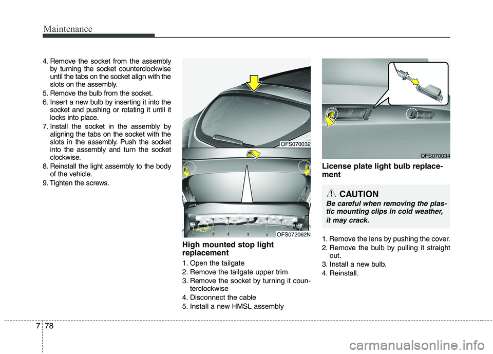
High mounted stop light
replacement
1. Open the tailgate
2. Remove the tailgate upper trim
3. Remove the socket by turning it coun-
terclockwise
4. Disconnect the cable
5. Install a new HMSL assembly
License plate light bulb replace-
ment
1. Remove the lens by pushing the cover.
2. Remove the bulb by pulling it straight
out.
3. Install a new bulb.
4. Reinstall.
OFS070034
CAUTION
Be careful when removing the plas-
tic mounting clips in cold weather,
it may crack.
OFS070032
OFS072062N
Page 355 of 384
779
Maintenance
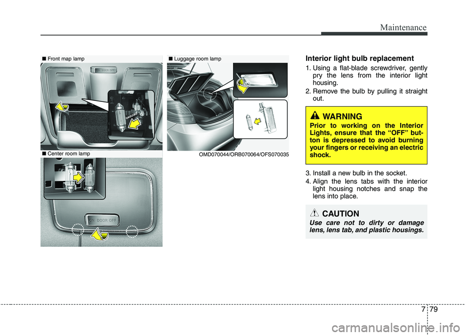
Interior light bulb replacement
1. Using a flat-blade screwdriver, gently
pry the lens from the interior light
housing.
2. Remove the bulb by pulling it straight
out.
3. Install a new bulb in the socket.
4. Align the lens tabs with the interior
light housing notches and snap the
lens into place.
WARNING
Prior to working on the Interior
Lights, ensure that the “OFF” but-
ton is depressed to avoid burning
your fingers or receiving an electric
shock.
CAUTION
Use care not to dirty or damage
lens, lens tab, and plastic housings.
■Luggage room lamp■Front map lamp
■Center room lamp
OMD070044/ORB070064/OFS070035
Page 362 of 384
Maintenance
86 7
EMISSION CONTROL SYSTEM
The emission control system of your
vehicle is covered by a written limited
warranty. Please see the warranty infor-
mation contained in the Owner’s
Handbook & Warranty Information book-
let in your vehicle.
Your vehicle is equipped with an emis-
sion control system to meet all applicable
emission regulations.
There are three emission control sys-
tems, as follows.
(1) Crankcase emission control system
(2) Evaporative emission control system
(3) Exhaust emission control system
In order to assure the proper function of
the emission control systems, it is rec-
ommended that you have your car
inspected and maintained by an author-
ized HYUNDAI dealer in accordance with
the maintenance schedule in this manu-
al.Caution for the Inspection and
Maintenance Test (With Electronic
Stability Control (ESC) system)
To prevent the vehicle from misfir-
ing during dynamometer testing,
turn the Electronic Stability Control
(ESC) system off by pressing the
ESC switch.
After dynamometer testing is com-
pleted, turn the ESC system back on
by pressing the ESC switch again.
1. Crankcase emission control
system
The positive crankcase ventilation sys-
tem is employed to prevent air pollution
caused by blow-by gases being emitted
from the crankcase. This system supplies
fresh filtered air to the crankcase through
the air intake hose. Inside the crankcase,
the fresh air mixes with blow-by gases,
which then pass through the PCV valve
into the induction system.
2. Evaporative emission control
(including ORVR: Onboard
Refueling Vapor Recovery)
system
The Evaporative Emission Control
System is designed to prevent fuel vapors
from escaping into the atmosphere.
(The ORVR system is designed to allow
the vapors from the fuel tank to be
loaded into a canister while refueling at
the gas station, preventing the escape of
fuel vapors into the atmosphere.)
Canister
Fuel vapors generated inside the fuel
tank are absorbed and stored in the
onboard canister. When the engine is
running, the fuel vapors absorbed in the
canister are drawn into the surge tank
through the purge control solenoid valve.
Purge Control Solenoid Valve (PCSV)
The purge control solenoid valve is con-
trolled by the Engine Control Module
(ECM); when the engine coolant tempera-
ture is low during idling, the PCSV closes
so that evaporated fuel is not taken into
the engine. After the engine warms-up
during ordinary driving, the PCSV opens
to introduce evaporated fuel to the engine.
Page 378 of 384
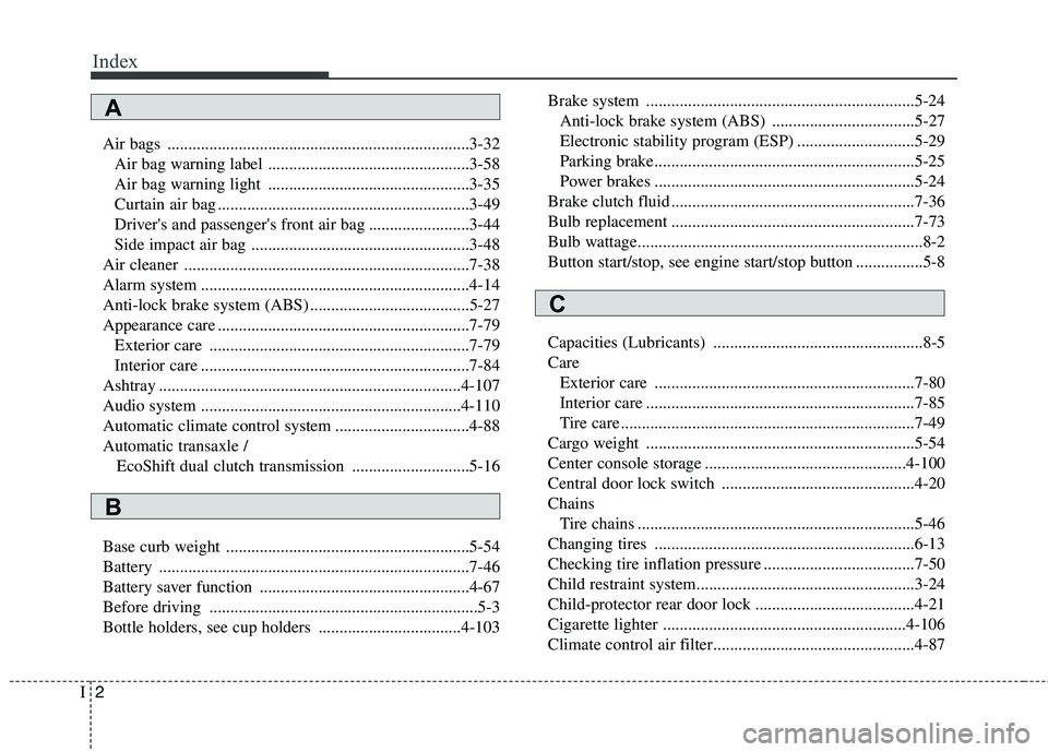
Index
2I
Air bags ........................................................................3-32
Air bag warning label ................................................3-58
Air bag warning light ................................................3-35
Curtain air bag ............................................................3-49
Driver's and passenger's front air bag ........................3-44
Side impact air bag ....................................................3-48
Air cleaner ....................................................................7-38
Alarm system ................................................................4-14
Anti-lock brake system (ABS) ......................................5-27
Appearance care ............................................................7-79
Exterior care ..............................................................7-79
Interior care ................................................................7-84
Ashtray ........................................................................4-107
Audio system ..............................................................4-110
Automatic climate control system ................................4-88
Automatic transaxle /
EcoShift dual clutch transmission ............................5-16
Base curb weight ..........................................................5-54
Battery ..........................................................................7-46
Battery saver function ..................................................4-67
Before driving ................................................................5-3
Bottle holders, see cup holders ..................................4-103Brake system ................................................................5-24
Anti-lock brake system (ABS) ..................................5-27
Electronic stability program (ESP) ............................5-29
Parking brake..............................................................5-25
Power brakes ..............................................................5-24
Brake clutch fluid ..........................................................7-36
Bulb replacement ..........................................................7-73
Bulb wattage....................................................................8-2
Button start/stop, see engine start/stop button ................5-8
Capacities (Lubricants) ..................................................8-5
Care
Exterior care ..............................................................7-80
Interior care ................................................................7-85
Tire care ......................................................................7-49
Cargo weight ................................................................5-54
Center console storage ................................................4-100
Central door lock switch ..............................................4-20
Chains
Tire chains ..................................................................5-46
Changing tires ..............................................................6-13
Checking tire inflation pressure ....................................7-50
Child restraint system....................................................3-24
Child-protector rear door lock ......................................4-21
Cigarette lighter ..........................................................4-106
Climate control air filter................................................4-87
A
B
C