light INFINITI FX 2012 Owners Manual
[x] Cancel search | Manufacturer: INFINITI, Model Year: 2012, Model line: FX, Model: INFINITI FX 2012Pages: 522, PDF Size: 3.51 MB
Page 207 of 522

4-30Monitor, climate, audio, phone and voice recognition systems
PREDICTIVE COURSE LINE SETTINGS
To turn ON or OFF the predictive course line
display, push theSETTINGbutton, select
the “Camera” key and push the ENTER
button.
Predictive Course Lines:
When this item is turned on, the predicted
course lines will be displayed on the
monitor when the selector lever is in the
R (Reverse) position.
HOW TO ADJUST SCREEN
To adjust the Display ON/OFF, Brightness,
Tint, Color, Contrast and Black Level of the
rearview monitor, push the SETTINGbutton
with the rearview monitor on, select the
“Display” key on the screen and select the
item key and adjust the level using the
INFINITI controller.
Do not adjust the Brightness, Tint, Color,
Contrast and Black Level of the rearview
monitor while the vehicle is moving. Make
sure the parking brake is firmly applied
and the engine is not running.
OPERATING TIPS
. When the selector lever is shifted to the
R (Reverse) position, the monitor
screen automatically changes to the
rearview monitor mode.
. It may take some time until the rearview
monitor is displayed after the selector
lever has been shifted to R from
another position or to another position
from R. Objects may be distorted
momentarily until the rearview monitor
screen is displayed completely.
. When the temperature is extremely high
or low, the screen may not clearly
display objects. This is not a malfunc-
tion.
. When strong light directly enters the
camera, objects may not be displayed
clearly. This is not a malfunction.
. Vertical lines may be seen in objects on
the screen. This is due to strong
reflected light from the bumper. This
is not a malfunction.
. The screen may flicker under fluores-
cent light. This is not a malfunction.
. The colors of objects on the rearview
monitor may differ somewhat from
those of the actual object. .
Objects on the monitor may not be clear
in a dark place or at night. This is not a
malfunction.
. If dirt, rain or snow attaches to the
camera, the rearview monitor may not
clearly display objects. Clean the cam-
era.
. Do not use alcohol, benzine or thinner
to clean the camera. This will cause
discoloration. To clean the camera,
wipe with a cloth dampened with
diluted mild cleaning agent and then
wipe with a dry cloth.
. Do not damage the camera as the
monitor screen may be adversely af-
fected.
. Do not use wax on the camera window.
Wipe off any wax with a clean cloth
dampened with mild detergent diluted
with water.
Page 212 of 522
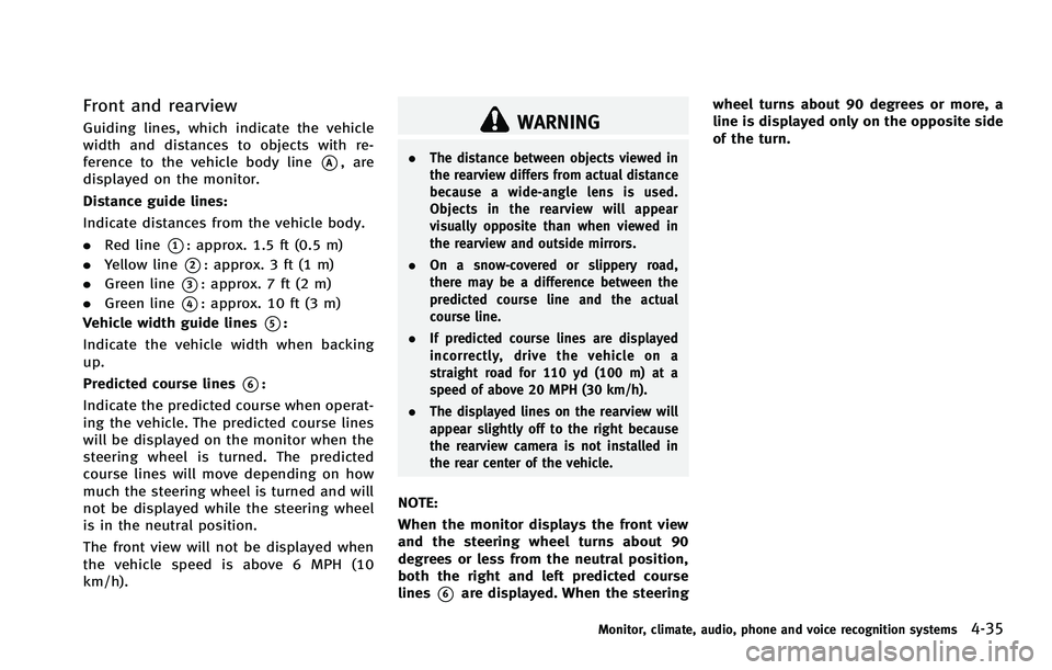
Front and rearview
Guiding lines, which indicate the vehicle
width and distances to objects with re-
ference to the vehicle body line
*A, are
displayed on the monitor.
Distance guide lines:
Indicate distances from the vehicle body.
. Red line
*1: approx. 1.5 ft (0.5 m)
. Yellow line
*2: approx. 3 ft (1 m)
. Green line
*3: approx. 7 ft (2 m)
. Green line
*4: approx. 10 ft (3 m)
Vehicle width guide lines
*5:
Indicate the vehicle width when backing
up.
Predicted course lines
*6:
Indicate the predicted course when operat-
ing the vehicle. The predicted course lines
will be displayed on the monitor when the
steering wheel is turned. The predicted
course lines will move depending on how
much the steering wheel is turned and will
not be displayed while the steering wheel
is in the neutral position.
The front view will not be displayed when
the vehicle speed is above 6 MPH (10
km/h).
WARNING
. The distance between objects viewed in
the rearview differs from actual distance
because a wide-angle lens is used.
Objects in the rearview will appear
visually opposite than when viewed in
the rearview and outside mirrors.
. On a snow-covered or slippery road,
there may be a difference between the
predicted course line and the actual
course line.
. If predicted course lines are displayed
incorrectly, drive the vehicle on a
straight road for 110 yd (100 m) at a
speed of above 20 MPH (30 km/h).
. The displayed lines on the rearview will
appear slightly off to the right because
the rearview camera is not installed in
the rear center of the vehicle.
NOTE:
When the monitor displays the front view
and the steering wheel turns about 90
degrees or less from the neutral position,
both the right and left predicted course
lines
*6are displayed. When the steering wheel turns about 90 degrees or more, a
line is displayed only on the opposite side
of the turn.
Monitor, climate, audio, phone and voice recognition systems4-35
Page 213 of 522
4-36Monitor, climate, audio, phone and voice recognition systems
SAA1841
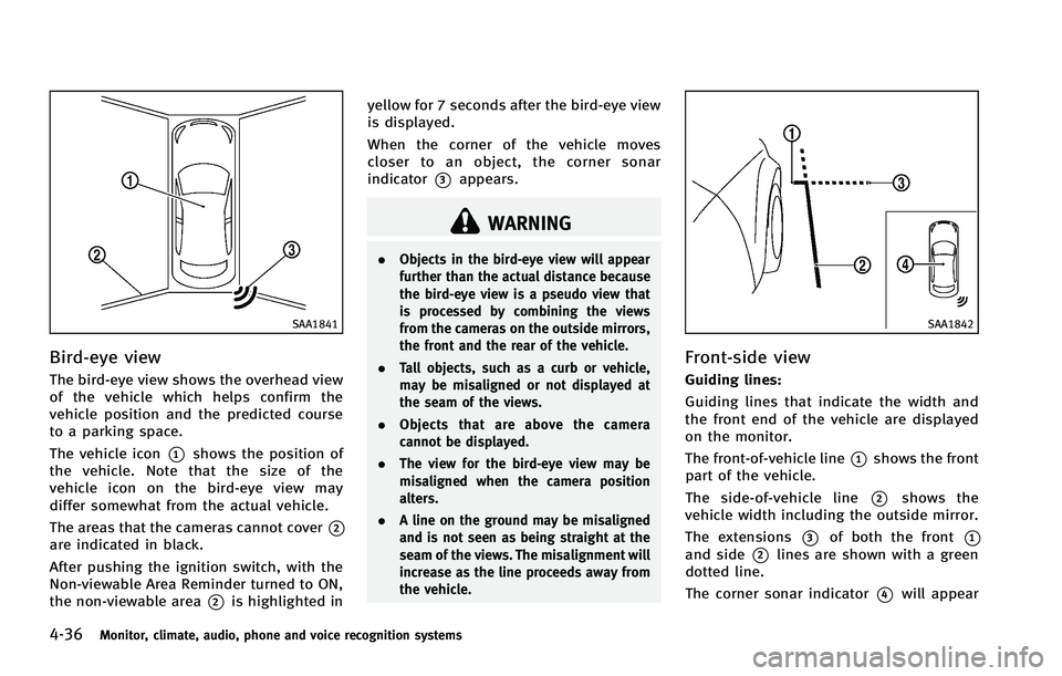
Bird-eye view
The bird-eye view shows the overhead view
of the vehicle which helps confirm the
vehicle position and the predicted course
to a parking space.
The vehicle icon
*1shows the position of
the vehicle. Note that the size of the
vehicle icon on the bird-eye view may
differ somewhat from the actual vehicle.
The areas that the cameras cannot cover
*2are indicated in black.
After pushing the ignition switch, with the
Non-viewable Area Reminder turned to ON,
the non-viewable area
*2is highlighted in yellow for 7 seconds after the bird-eye view
is displayed.
When the corner of the vehicle moves
closer to an object, the corner sonar
indicator
*3appears.
WARNING
.
Objects in the bird-eye view will appear
further than the actual distance because
the bird-eye view is a pseudo view that
is processed by combining the views
from the cameras on the outside mirrors,
the front and the rear of the vehicle.
. Tall objects, such as a curb or vehicle,
may be misaligned or not displayed at
the seam of the views.
. Objects that are above the camera
cannot be displayed.
. The view for the bird-eye view may be
misaligned when the camera position
alters.
. A line on the ground may be misaligned
and is not seen as being straight at the
seam of the views. The misalignment will
increase as the line proceeds away from
the vehicle.
SAA1842
Front-side view
Guiding lines:
Guiding lines that indicate the width and
the front end of the vehicle are displayed
on the monitor.
The front-of-vehicle line
*1shows the front
part of the vehicle.
The side-of-vehicle line
*2shows the
vehicle width including the outside mirror.
The extensions
*3of both the front*1and side*2lines are shown with a green
dotted line.
The corner sonar indicator
*4will appear
Page 214 of 522
when a corner of the vehicle moves closer
to an object.
The corner sonar indicator
*4can be
turned off. See “Around view monitor
settings” (P.4-41).
CAUTION
The turn signal light may overlap with the
side-of-vehicle line. This is not a malfunc-
tion.
Infrared illumination:
The images on the front-side view can be
displayed at night using the infrared
illumination on the outside mirror.SAA2629
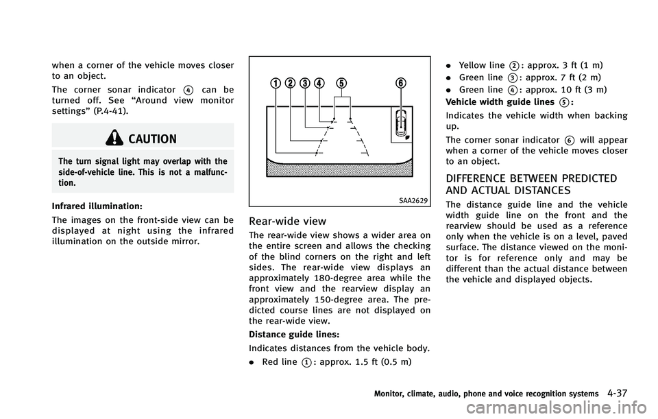
Rear-wide view
The rear-wide view shows a wider area on
the entire screen and allows the checking
of the blind corners on the right and left
sides. The rear-wide view displays an
approximately 180-degree area while the
front view and the rearview display an
approximately 150-degree area. The pre-
dicted course lines are not displayed on
the rear-wide view.
Distance guide lines:
Indicates distances from the vehicle body.
.Red line
*1: approx. 1.5 ft (0.5 m) .
Yellow line
*2: approx. 3 ft (1 m)
. Green line
*3: approx. 7 ft (2 m)
. Green line
*4: approx. 10 ft (3 m)
Vehicle width guide lines
*5:
Indicates the vehicle width when backing
up.
The corner sonar indicator
*6will appear
when a corner of the vehicle moves closer
to an object.
DIFFERENCE BETWEEN PREDICTED
AND ACTUAL DISTANCES
The distance guide line and the vehicle
width guide line on the front and the
rearview should be used as a reference
only when the vehicle is on a level, paved
surface. The distance viewed on the moni-
tor is for reference only and may be
different than the actual distance between
the vehicle and displayed objects.
Monitor, climate, audio, phone and voice recognition systems4-37
Page 218 of 522
SAA3649
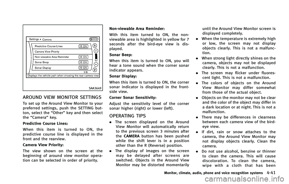
AROUND VIEW MONITOR SETTINGS
To set up the Around View Monitor to your
preferred settings, push the SETTING but-
ton, select the“Other”key and then select
the “Camera ”key.
Predictive Course Lines:
When this item is turned to ON, the
predictive course line is displayed in the
front and the rearview.
Camera View Priority:
The view shown on the screen at the
beginning of around view monitor opera-
tion can be selected in order of priority. Non-viewable Area Reminder:
With this item turned to ON, the non-
viewable area is highlighted in yellow for 7
seconds after the bird-eye view is dis-
played.
Sonar Beep:
When this item is turned to ON, you will
hear a tone sound when the corner sonar
indicator appears.
Sonar Display:
When this item is turned to ON, the corner
sonar indicator is displayed in the front-
side view.
Corner Sonar Sensitivity:
Adjust the sensitivity level of the corner
sonar higher (right) or lower (left).
OPERATING TIPS
.
The screen displayed on the Around
View Monitor will automatically return
to the previous screen 3 minutes after
the CAMERA button has been pushed
while the shift lever is in a position
other than the R (Reverse) position.
. The display of images on the screen
may be delayed after screens are
switched. Objects in the Around View
Monitor may be distorted momentarily until the Around View Monitor screen is
displayed completely.
. When the temperature is extremely high
or low, the screen may not display
objects clearly. This is not a malfunc-
tion.
. When strong light directly shines on the
camera, objects may not be displayed
clearly. This is not a malfunction.
. The screen may flicker under fluores-
cent light. This is not a malfunction.
. The colors of objects on the Around
View Monitor may differ somewhat
from those of the actual object.
. Objects on the monitor may not be clear
and the color of the object may differ in
a dark location or at night. This is not a
malfunction.
. There may be differences in clearness
between each camera view of the bird-
eye view.
. If dirt, rain or snow attaches to the
camera, the Around View Monitor may
not display objects clearly. Clean the
camera.
. Do not use alcohol, benzine or thinner
to clean the camera. This will cause
discoloration. To clean the camera,
wipe with a cloth that has been
Monitor, climate, audio, phone and voice recognition systems4-41
Page 222 of 522

AUTOMATIC CLIMATE CONTROL
Automatic operation
Cooling and/or dehumidified heating
(AUTO):
This mode may be used all year round. The
system works automatically to control the
inside temperature, air flow distribution
and fan speed after the preferred tempera-
ture is set manually.
1. Push the“AUTO” button on. (The
indicator on the button will illuminate
and AUTO will be displayed.)
2. Turn the temperature control dial (dri- ver side) to set the desired tempera-
ture.
.The temperature can be set withinthe following range.
— For U.S.: 60 to 908F
— For Canada: 18 to 328C
.The temperature of the passenger
compartment will be maintained
automatically. Air flow distribution
and fan speed will also be controlled
automatically.
3. You can individually set driver and front passenger side temperature using each
temperature control button. When the “DUAL”
button is pushed or the pas-
senger side temperature control button
is turned, the DUAL indicator will come
on. To turn off the passenger side
temperature control, push the “DUAL”
button.
4. To turn off the climate control system, push the “OFF”button.
A visible mist may be seen coming from the
ventilators in hot, humid conditions as the
air is cooled rapidly. This does not indicate
a malfunction.
Heating (A/C OFF): The air conditioner does not activate in this
mode. When you need to heat only, use
this mode.
1. Push the “AUTO”button on.
2. Push the “A/C” button. (The A/C
indicator will turn off.)
3. Turn the temperature control dial to set the desired temperature.
. The temperature of the passenger
compartment will be maintained auto-
matically. Air flow distribution and fan
speed are also controlled automati-
cally. .
Do not set the temperature lower than
the outside air temperature. Otherwise
the system may not work properly.
. Not recommended if windows fog up.
Dehumidified defrosting or defogging: 1. Push the “
”front defroster button.
(The indicator light on the button will
illuminate.)
2. Turn the temperature control dial to set the desired temperature.
. To quickly remove ice from the outside
of the windows, push the fan speed
increase button “
”and set it to the
maximum position.
. As soon as possible after the wind-
shield is clean, push the “AUTO”button
to return to the auto mode.
. When the “
”front defroster button
is pushed, the air conditioner will
automatically be turned on at outside
temperatures above 238 F(−58C) to
defog the windshield, and the air
recirculate mode will automatically be
turned off.
Outside air is drawn into the passenger
compartment to improve the defogging
performance.
Monitor, climate, audio, phone and voice recognition systems4-45
Page 223 of 522

4-46Monitor, climate, audio, phone and voice recognition systems
Manual operation
Fan speed control:
Push the fan speed increase“
”or
decrease “”buttons to manually con-
trol the fan speed.
Push the “AUTO” button to return to
automatic control of the fan speed.
Air recirculation:
Push the intake air control button to
recirculate interior air inside the vehicle.
The indicator light on the “
”side will
illuminate.
The air recirculation mode cannot be
activated when the air conditioner is in
the front defrosting mode “
”.
Outside air circulation:
Push the intake air control button to draw
outside air into the passenger compart-
ment. The indicator light on the “
”side
will turn off and “”(if so equipped) will
illuminate.
Automatic intake air control:
In the AUTO mode, the intake air will be
controlled automatically. To manually con-
trol the intake air, push the intake air
control button. .
Without Advanced Climate Control Sys-
tem (ACCS):
To return to the automatic control
mode, push the intake air control
button for about 2 seconds. The in-
dicator lights (both air recirculation
“
” and outside air circulation
“” sides) will flash twice, and then
the intake air will be controlled auto-
matically.
. With Advanced Climate Control System
(ACCS):
To return to the automatic control
mode, push the intake air control
button until the indicator light on the
“
” side illuminates. The Advanced
Climate Control System (ACCS) turns on
and the intake air will be controlled
automatically.
Air flow control:
Pushing the “MODE” manual air flow
control button selects the air outlet to:
: Air flows from center and side ventilators.
: Air flows from center and side ventilators and foot outlets.
: Air flows mainly from foot outlets.
: Air flows from defroster and foot outlets.
To turn the system off
Push the “OFF”button.
Advanced Climate Control System
(ACCS) (if so equipped)
The Advanced Climate Control System
(ACCS) keeps the air inside of the vehicle
clean, using the ion control and the
automatic air intake control with outside
odor and exhaust gas detecting sensor.
Page 224 of 522
SAA2734
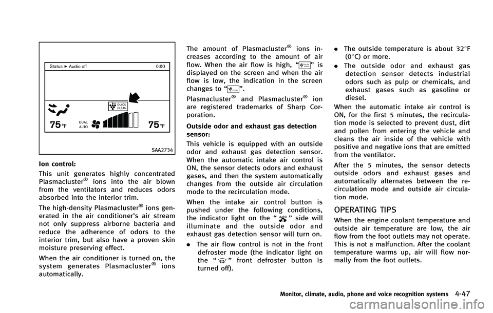
Ion control:
This unit generates highly concentrated
Plasmacluster
®ions into the air blown
from the ventilators and reduces odors
absorbed into the interior trim.
The high-density Plasmacluster
®ions gen-
erated in the air conditioner’s air stream
not only suppress airborne bacteria and
reduce the adherence of odors to the
interior trim, but also have a proven skin
moisture preserving effect.
When the air conditioner is turned on, the
system generates Plasmacluster
®ions
automatically. The amount of Plasmacluster
®ions in-
creases according to the amount of air
flow. When the air flow is high, “
”is
displayed on the screen and when the air
flow is low, the indication in the screen
changes to “
”.
Plasmacluster®and Plasmacluster®ion
are registered trademarks of Sharp Cor-
poration.
Outside odor and exhaust gas detection
sensor:
This vehicle is equipped with an outside
odor and exhaust gas detection sensor.
When the automatic intake air control is
ON, the sensor detects odors and exhaust
gases, and then the system automatically
changes from the outside air circulation
mode to the recirculation mode.
When the intake air control button is
pushed under the following conditions,
the indicator light on the “
”side will
illuminate and the outside odor and
exhaust gas detection sensor will turn on.
. The air flow control is not in the front
defroster mode (the indicator light on
the “
”front defroster button is
turned off). .
The outside temperature is about 328F
(08C) or more.
. The outside odor and exhaust gas
detection sensor detects industrial
odors such as pulp or chemicals, and
exhaust gases such as gasoline or
diesel.
When the automatic intake air control is
ON, for the first 5 minutes, the recircula-
tion mode is selected to prevent dust, dirt
and pollen from entering the vehicle and
cleans the air inside of the vehicle with
positive and negative ions that are emitted
from the ventilator.
After the 5 minutes, the sensor detects
outside odors and exhaust gases and
automatically alternates between the re-
circulation mode and outside air circula-
tion mode.
OPERATING TIPS
When the engine coolant temperature and
outside air temperature are low, the air
flow from the foot outlets may not operate.
This is not a malfunction. After the coolant
temperature warms up, air will flow nor-
mally from the foot outlets.
Monitor, climate, audio, phone and voice recognition systems4-47
Page 226 of 522
AUDIO OPERATION PRECAUTIONS
Radio
Push the ignition switch to the ACC or ON
position and push the radio band select
button to turn on the radio. If you listen to
the radio with the engine not running, the
ignition switch should be pushed to the
ACC position.
Radio reception is affected by station
signal strength, distance from radio trans-
mitter, buildings, bridges, mountains and
other external influences. Intermittent
changes in reception quality normally are
caused by these external influences.
Using a cellular phone in or near the
vehicle may influence radio reception
quality.
Radio reception:
Your INFINITI radio system is equipped with
state-of-the-art electronic circuits to en-
hance radio reception. These circuits are
designed to extend reception range, and to
enhance the quality of that reception.
However there are some general character-
istics of both FM and AM radio signals that
can affect radio reception quality in a
moving vehicle, even when the finestequipment is used. These characteristics
are completely normal in a given reception
area, and do not indicate any malfunction
in your INFINITI radio system.
Reception conditions will constantly
change because of vehicle movement.
Buildings, terrain, signal distance and
interference from other vehicles can work
against ideal reception. Described below
are some of the factors that can affect your
radio reception.
Some cellular phones or other devices may
cause interference or a buzzing noise to
come from the audio system speakers.
Storing the device in a different location
may reduce or eliminate the noise.
SAA0306
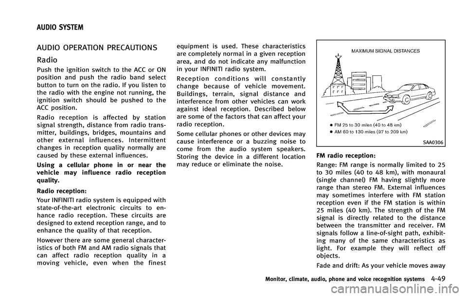
FM radio reception:
Range: FM range is normally limited to 25
to 30 miles (40 to 48 km), with monaural
(single channel) FM having slightly more
range than stereo FM. External influences
may sometimes interfere with FM station
reception even if the FM station is within
25 miles (40 km). The strength of the FM
signal is directly related to the distance
between the transmitter and receiver. FM
signals follow a line-of-sight path, exhibit-
ing many of the same characteristics as
light. For example they will reflect off
objects.
Fade and drift: As your vehicle moves away
Monitor, climate, audio, phone and voice recognition systems4-49
AUDIO SYSTEM
Page 227 of 522
4-50Monitor, climate, audio, phone and voice recognition systems
from a station transmitter, the signals will
tend to fade and/or drift.
Static and flutter: During signal interfer-
ence from buildings, large hills or due to
antenna position, usually in conjunction
with increased distance from the station
transmitter, static or flutter can be heard.
This can be reduced by lowering the treble
setting to reduce the treble response.
Multipath reception: Because of the reflec-
tive characteristics of FM signals, direct
and reflected signals reach the receiver at
the same time. The signals may cancel
each other, resulting in momentary flutter
or loss of sound.
AM radio reception:
AM signals, because of their low frequency,
can bend around objects and skip along
the ground. In addition, the signals can be
bounced off the ionosphere and bent back
to earth. Because of these characteristics.
AM signals are also subject to interference
as they travel from transmitter to receiver.
Fading: Occurs while the vehicle is passing
through freeway underpasses or in areas
with many tall buildings. It can also occur
for several seconds during ionospheric
turbulence even in areas where no obsta-cles exist.
Static: Caused by thunderstorms, electrical
power lines, electric signs and even traffic
lights.
Satellite radio reception:
When the satellite radio is used for the first
time or the battery has been replaced, the
satellite radio may not work properly. This
is not a malfunction. Wait more than 10
minutes with the satellite radio ON and the
vehicle outside of any metal or large
building for the satellite radio to receive
all of the necessary data.
The satellite radio mode requires an active
XM Satellite Radio
®subscription. The
satellite radio is not available in Alaska,
Hawaii and Guam.
The satellite radio performance may be
affected if cargo carried on the roof blocks
the satellite radio signal.
If possible, do not put cargo near the
satellite antenna.
A build up of ice on the satellite radio
antenna can affect satellite radio perfor-
mance. Remove the ice to restore satellite
radio reception.
SAA0480
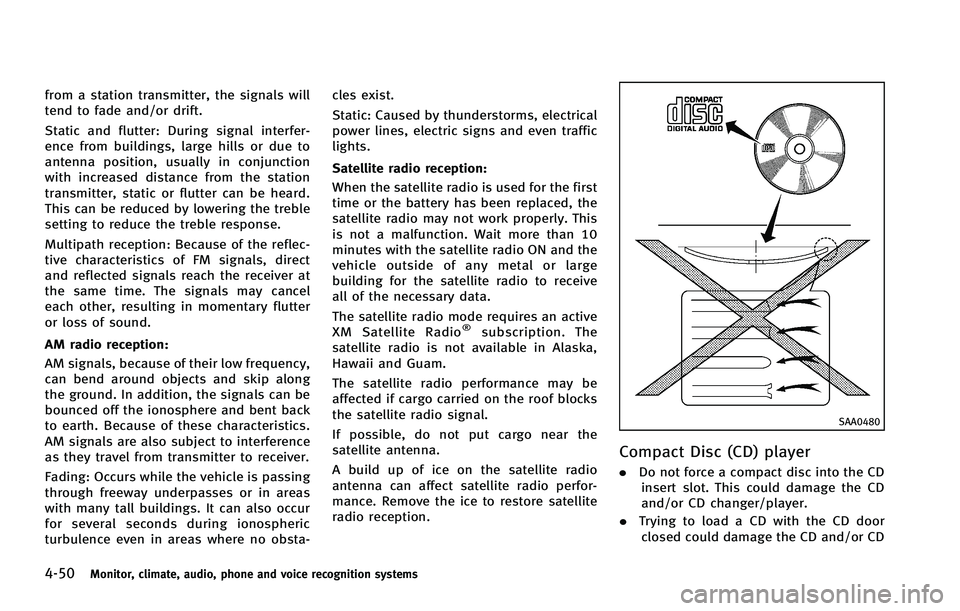
Compact Disc (CD) player
. Do not force a compact disc into the CD
insert slot. This could damage the CD
and/or CD changer/player.
. Trying to load a CD with the CD door
closed could damage the CD and/or CD