power steering INFINITI FX 2012 Owners Manual
[x] Cancel search | Manufacturer: INFINITI, Model Year: 2012, Model line: FX, Model: INFINITI FX 2012Pages: 522, PDF Size: 3.51 MB
Page 14 of 522
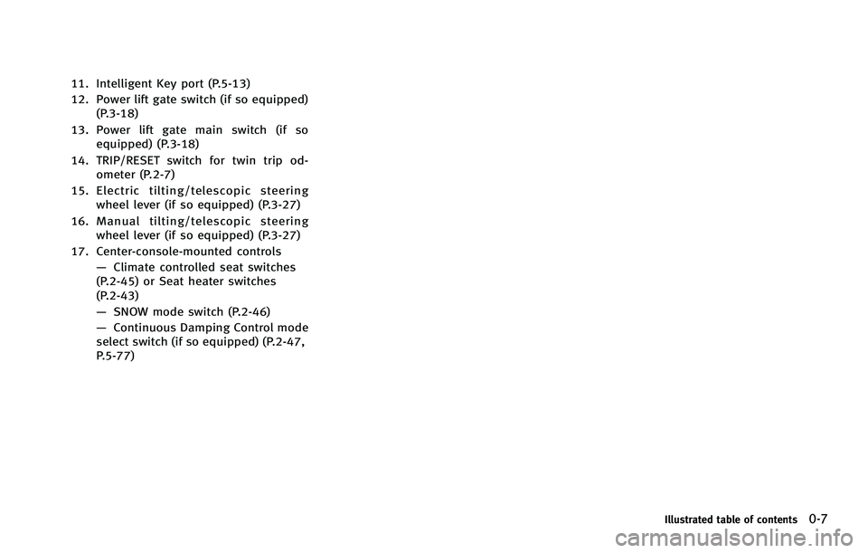
11. Intelligent Key port (P.5-13)
12. Power lift gate switch (if so equipped)(P.3-18)
13. Power lift gate main switch (if so equipped) (P.3-18)
14. TRIP/RESET switch for twin trip od- ometer (P.2-7)
15. Electric tilting/telescopic steering wheel lever (if so equipped) (P.3-27)
16. Manual tilting/telescopic steering wheel lever (if so equipped) (P.3-27)
17. Center-console-mounted controls —Climate controlled seat switches
(P.2-45) or Seat heater switches
(P.2-43)
— SNOW mode switch (P.2-46)
— Continuous Damping Control mode
select switch (if so equipped) (P.2-47,
P.5-77)
Illustrated table of contents0-7
Page 15 of 522
0-8Illustrated table of contents
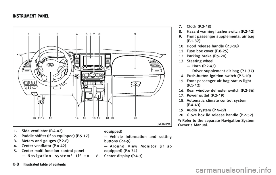
JVC0209X
1. Side ventilator (P.4-42)
2. Paddle shifter (if so equipped) (P.5-17)
3. Meters and gauges (P.2-6)
4. Center ventilator (P.4-42)
5. Center multi-function control panel—Navigation system* (if so equipped)
—
Vehicle information and setting
buttons (P.4-9)
— Around View Monitor (if so
equipped) (P.4-31)
6. Center display (P.4-3) 7. Clock (P.2-48)
8. Hazard warning flasher switch (P.2-42)
9. Front passenger supplemental air bag
(P.1-37)
10. Hood release handle (P.3-18)
11. Fuse box cover (P.8-25)
12. Parking brake (P.5-20)
13. Steering wheel —Horn (P.2-43)
— Driver supplement air bag (P.1-37)
14. Push-button ignition switch (P.5-10)
15. Front passenger air bag status light (P.1-42)
16. Rear window defroster switch (P.2-36)
17. Power outlet (P.2-49)
18. Automatic climate control system (P.4-43)
19. Audio system (P.4-49)
20. Glove box lid release handle (P.2-52)
*: Refer to the separate Navigation System
Owner’s Manual.
INSTRUMENT PANEL
Page 17 of 522
0-10Illustrated table of contents
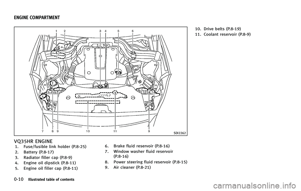
SDI2262
VQ35HR ENGINE1. Fuse/fusible link holder (P.8-25)
2. Battery (P.8-17)
3. Radiator filler cap (P.8-9)
4. Engine oil dipstick (P.8-11)
5. Engine oil filler cap (P.8-11)6. Brake fluid reservoir (P.8-16)
7. Window washer fluid reservoir
(P.8-16)
8. Power steering fluid reservoir (P.8-15)
9. Air cleaner (P.8-21) 10. Drive belts (P.8-19)
11. Coolant reservoir (P.8-9)
ENGINE COMPARTMENT
Page 18 of 522
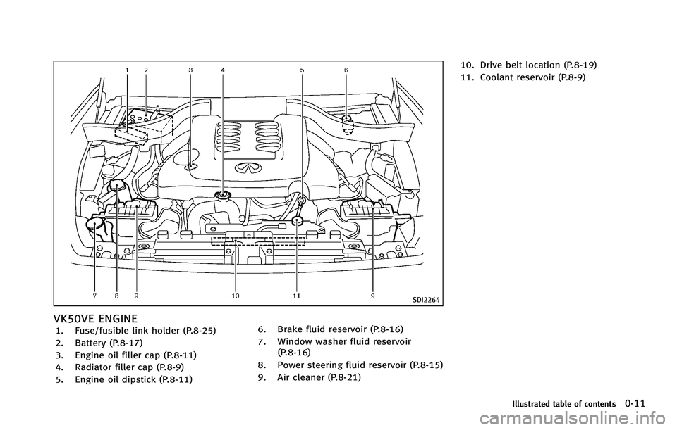
SDI2264
VK50VE ENGINE1. Fuse/fusible link holder (P.8-25)
2. Battery (P.8-17)
3. Engine oil filler cap (P.8-11)
4. Radiator filler cap (P.8-9)
5. Engine oil dipstick (P.8-11)6. Brake fluid reservoir (P.8-16)
7. Window washer fluid reservoir
(P.8-16)
8. Power steering fluid reservoir (P.8-15)
9. Air cleaner (P.8-21) 10. Drive belt location (P.8-19)
11. Coolant reservoir (P.8-9)
Illustrated table of contents0-11
Page 74 of 522
SIC4246
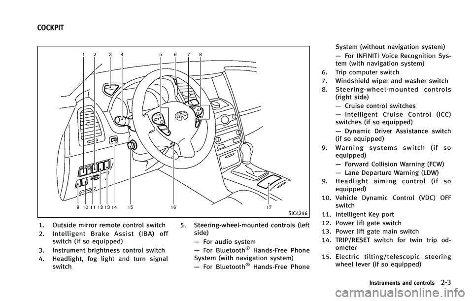
1. Outside mirror remote control switch
2. Intelligent Brake Assist (IBA) offswitch (if so equipped)
3. Instrument brightness control switch
4. Headlight, fog light and turn signal switch 5. Steering-wheel-mounted controls (left
side)
—For audio system
— For Bluetooth
®Hands-Free Phone
System (with navigation system)
— For Bluetooth
®Hands-Free Phone System (without navigation system)
—
For INFINITI Voice Recognition Sys-
tem (with navigation system)
6. Trip computer switch
7. Windshield wiper and washer switch
8. Steering-wheel-mounted controls (right side)
—Cruise control switches
— Intelligent Cruise Control (ICC)
switches (if so equipped)
— Dynamic Driver Assistance switch
(if so equipped)
9. Warning systems switch (if so equipped)
—Forward Collision Warning (FCW)
— Lane Departure Warning (LDW)
9. Headlight aiming control (if so equipped)
10. Vehicle Dynamic Control (VDC) OFF switch
11. Intelligent Key port
12. Power lift gate switch
13. Power lift gate main switch
14. TRIP/RESET switch for twin trip od- ometer
15. Electric tilting/telescopic steering wheel lever (if so equipped)
Instruments and controls2-3
COCKPIT
Page 76 of 522
JVC0209X
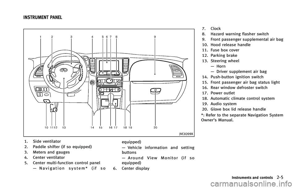
1. Side ventilator
2. Paddle shifter (if so equipped)
3. Meters and gauges
4. Center ventilator
5. Center multi-function control panel—Navigation system* (if so equipped)
—
Vehicle information and setting
buttons
— Around View Monitor (if so
equipped)
6. Center display 7. Clock
8. Hazard warning flasher switch
9. Front passenger supplemental air bag
10. Hood release handle
11. Fuse box cover
12. Parking brake
13. Steering wheel
—Horn
— Driver supplement air bag
14. Push-button ignition switch
15. Front passenger air bag status light
16. Rear window defroster switch
17. Power outlet
18. Automatic climate control system
19. Audio system
20. Glove box lid release handle
*: Refer to the separate Navigation System
Owner’s Manual.
Instruments and controls2-5
INSTRUMENT PANEL
Page 142 of 522
3 Pre-driving checks and adjustments
Keys .................................................................... 3-2Intelligent Key ................................................. 3-2
Valet hand-off.................................................. 3-4
Doors .................................................................. 3-4 Locking with mechanical key ........................... 3-4
Opening and closing windows with the
mechanical key................................................ 3-5
Locking with inside lock knob ......................... 3-5
Locking with power door lock switch ............... 3-5
Automatic door locks....................................... 3-6
Child safety rear door lock .............................. 3-6
Intelligent Key system ......................................... 3-7 Intelligent Key operating range ........................ 3-9
Door locks/unlocks precaution ........................ 3-9
Intelligent Key operation ............................... 3-10
Battery saver system ..................................... 3-12
Warning signals............................................. 3-12 Troubleshooting guide ................................... 3-13
Remote keyless entry system............................. 3-14 How to use remote keyless entry system....... 3-15
Hood ................................................................. 3-18 Lift gate ............................................................ 3-18
Operating manual lift gate ........................... 3-19
Operating power lift gate (if so equipped).... 3-19
Auto closure ................................................ 3-24
Lift gate release lever .................................. 3-24
Fuel-filler door................................................... 3-24
Opening the fuel-filler door.......................... 3-24Fuel-filler cap............................................... 3-25
Tilt/telescopic steering ...................................... 3-27 Manual operation (if so equipped) ............... 3-27
Electric operation (if so equipped) ............... 3-28
Sun visors......................................................... 3-28 Mirrors .............................................................. 3-29
Inside mirror................................................ 3-29
Outside mirrors............................................ 3-30
Vanity mirror................................................ 3-32
Automatic drive positioner (if so equipped) ....... 3-32 Entry/exit function ....................................... 3-32
Seat synchronization function ...................... 3-33
Memory storage........................................... 3-34
System operation......................................... 3-35
Page 174 of 522
Cancel or activate entry/exit func-
tion
The selector lever must be in the P (Park)
position with the ignition switch in the OFF
position.
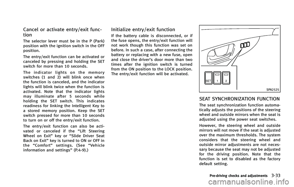
The entry/exit function can be activated or
canceled by pressing and holding the SET
switch for more than 10 seconds.
The indicator lights on the memory
switches (1 and 2) will blink once when
the function is canceled, and the indicator
lights will blink twice when the function is
activated. Note that the indicator lights
may illuminate after 5 seconds while
holding the SET switch. This indicates
readiness for linking the Intelligent Key to
a stored memory position. Keep the SET
switch pressed for more than 10 seconds
to turn on or off the entry/exit function.
The entry/exit function can also be acti-
vated or canceled if the“Lift Steering
Wheel on Exit” key or“Slide Driver Seat
Back on Exit” key is turned to ON or OFF in
the “Comfort” settings. (See “Vehicle
information and settings” (P.4-9).)
Initialize entry/exit function
If the battery cable is disconnected, or if
the fuse opens, the entry/exit function will
not work though this function was set on
before. In such a case, after connecting the
battery or replacing with a new fuse, open
and close the driver’s door more than two
times after the ignition switch is turned
from the ON position to the LOCK position.
The entry/exit function will be activated.
SPA2525
SEAT SYNCHRONIZATION FUNCTION
The seat synchronization function automa-
tically adjusts the positions of the steering
wheel and outside mirrors when the seat is
adjusted using the power seat switches.
However, the steering wheel and outside
mirrors will not move if the seat is adjusted
over the maximum thresholds. The system
considers that the steering wheel and
outside mirror adjustments are not neces-
sary because the seat may not be adjusted
for the driving position. Note that the
function is set to disabled as the factory
default setting.
Pre-driving checks and adjustments3-33
Page 327 of 522
Forward Collision Warning (FCW) system
(if so equipped) ................................................. 5-67Precautions on FCW system ........................... 5-68
Intelligent Brake Assist (IBA) system (if
so equipped) ..................................................... 5-70 Precautions on IBA system ............................ 5-71
Break-in schedule .............................................. 5-74
Increasing fuel economy .................................... 5-74
All-Wheel Drive (AWD) (if so equipped) .............. 5-75
Parking/parking on hills .................................... 5-76
Power steering................................................... 5-77
Continuous damping control (if so equipped)..... 5-77
Brake system..................................................... 5-78 Braking precautions ...................................... 5-78
European design brake pads (if
so equipped) ................................................. 5-78
Parking brake break-in .................................. 5-79 Brake assist ...................................................... 5-79
Brake assist................................................. 5-79Preview function (Intelligent Cruise Control
system equipped models) ............................ 5-79
Anti-lock Braking System (ABS) .................... 5-82
Vehicle Dynamic Control (VDC) system .............. 5-83
Rear active steer system (if so equipped) .......... 5-85
Cold weather driving ......................................... 5-85
Freeing a frozen door lock ........................... 5-85
Antifreeze .................................................... 5-85
Battery......................................................... 5-85
Draining of coolant water............................. 5-85
Tire equipment ............................................ 5-86
Special winter equipment ............................ 5-86
Driving on snow or ice ................................. 5-86
Engine block heater (if so equipped)............ 5-87
Page 402 of 522
2. Move the selector lever to the P (Park)position.
3. To help prevent the vehicle from rolling into the street when parked on a
sloping drive way, it is a good practice
to turn the wheels as illustrated.
.HEADED DOWNHILL WITH CURB:*1
Turn the wheels into the curb and
move the vehicle forward until the
curb side wheel gently touches the
curb.
.HEADED UPHILL WITH CURB:*2
Turn the wheels away from the curb
and move the vehicle back until the
curb side wheel gently touches the
curb.
.HEADED UPHILL OR DOWNHILL, NOCURB:
*3
Turn the wheels toward the side of
the road so the vehicle will move
away from the center of the road if it
moves.
4. Push the ignition switch to the OFF position.
WARNING
If the engine is not running or is turned off
while driving, the power assist for the
steering will not work. Steering will be
harder to operate.
The power assisted steering uses a hy-
draulic pump, driven by the engine, to
assist steering.
If the engine stops or the drive belt breaks,
you will still have control of the vehicle.
However, much greater steering effort is
needed, especially in sharp turns and at
low speeds.
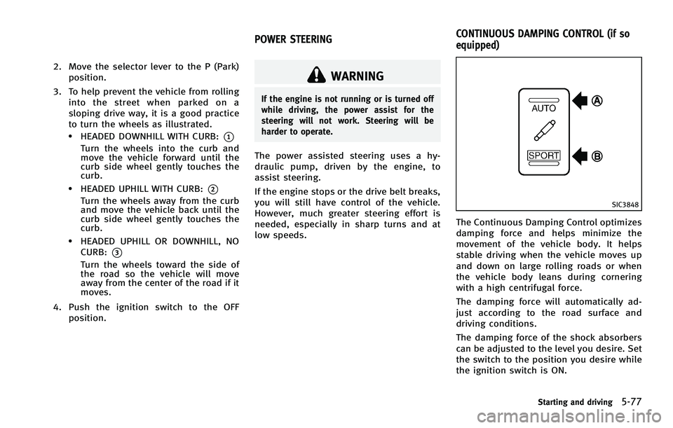
SIC3848
The Continuous Damping Control optimizes
damping force and helps minimize the
movement of the vehicle body. It helps
stable driving when the vehicle moves up
and down on large rolling roads or when
the vehicle body leans during cornering
with a high centrifugal force.
The damping force will automatically ad-
just according to the road surface and
driving conditions.
The damping force of the shock absorbers
can be adjusted to the level you desire. Set
the switch to the position you desire while
the ignition switch is ON.
Starting and driving5-77
POWER STEERING CONTINUOUS DAMPING CONTROL (if so
equipped)